Desiccant Enhanced Evaporative Air-Conditioning phần 3 ppsx
Bạn đang xem bản rút gọn của tài liệu. Xem và tải ngay bản đầy đủ của tài liệu tại đây (4.98 MB, 10 trang )
volume is frozen (Ice Energy 2010). This storage can be useful to enable maximum thermal use
from solar or on-site CHP. LDACs leverage the latent storage capacity by producing more total
cooling than the stored latent cooling. For example, an LDAC may use 2 ton·h of latent storage,
but deliver 4 ton·h of total cooling. This is derived from an additional 2 tons of sensible cooling
accomplished by the evaporative cooling system.
Figure 2-7 LDAC schematic
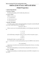
The latent COP for DEVap is 1.2–1.4, because it requires only modest salt concentration to
function properly (30%–38% LiCl). Figure 2-8 shows the calculated efficiency of a two-stage
regenerator using natural gas as the heat source. Moisture removal rate is also shown where the
nominal rate is 3 tons of latent removal.
11
2 Stage Regenerator Performance
(30 kbtu gas input, T
amb,wb
= 78°F, ∆C
LiCl
= 8% )
4.00
3.50
3.00
2.50
2.00
MRR
1.50
COP_Latent
1.00
0.50
0.00
Inlet Desiccant Concentration (% by weight)
Figure 2-8 Calculated two-stage regenerator moisture removal rate and efficiency performance
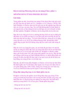
2.3.2 DEVap Process: Air Flow Channel Using Membranes (NREL Patented
Design)
This section describes how the LDAC process is enhanced with NREL’s DEVap concept. The
DEVap process follows:
1. Ventilation air [1] and warm indoor air [2] are mixed into a single air stream.
2. This mixed air stream (now the product air) is drawn through the top channel in the heat
exchange pair.
3. The product air stream is brought into intimate contact with the drying potential of the
liquid desiccant [d] through a vapor-permeable membrane [e].
4. Dehumidification [ii] occurs as the desiccant absorbs water vapor from the product air.
5. The product air stream is cooled and dehumidified, then supplied to the building space
[3].
6. A portion of the product air, which has had its dew point reduced (dehumidified), is
drawn through the bottom channel of the heat exchange pair and acts as the secondary air
stream.
7. The secondary air stream is brought into intimate contact with the water layer [c] through
a vapor-permeable membrane [b].
8. The two air streams are structurally separated by thin plastic sheets [a] through which
thermal energy flows, including the heat of absorption [i].
9. Water evaporates through the membranes and is transferred to the air stream [iii].
10. The secondary air stream is exhausted [4] to the outside as hot humid air.
MRR (tons) and Latent COP (Site)
20% 25% 30% 35% 40%
12
d. Liquid
Desiccant
i. Heat Transfer
1. Ventilation Air
2. Warm Indoor Air
4. Humid Exhaust
iii. Water
Evaporation
(Cooling Effect)
3. Cool-Dry
Supply Air
b. Membrane
c. Water
ii. Dehumidification
a. Plastic
Sheets
e. Membrane
Figure 2-9 Physical DEVap concept description
NREL has applied for international patent protection for the DEVap concept and variations
(Alliance for Sustainable Energy LLC 2008).
The water-side membrane implementation of DEVap is part of the original concept, but is not a
necessary component. Its advantages are:
• Complete water containment. It completely solves problems with sumps and water
droplets entrained into the air stream.
• Dry surfaces. The surface of the membrane becomes a “dry to the touch” surface that is
made completely of plastic and resists biological growth.
The water-side membrane may not be necessary in the DEVap configuration, according to strong
evidence from companies (e.g., Coolerado Cooler, Speakman – OASys) that have used wicked
surfaces to create successful evaporative coolers. Omitting this membrane would result in cost
savings.
The desiccant-side membrane is necessary to guarantee complete containment of the desiccant
droplets and create a closed circuit to prevent desiccant leaks. It should have the following
properties:
• Complete desiccant containment. Breakthrough pressure (at which desiccant can be
pushed through the micro-size pores) should be about 20 psi or greater.
• Water vapor permeability. The membrane should be thin (~25 μm) and have a pore
size of about 0.1 μm. Its open area should exceed 70% to promote vapor transport.
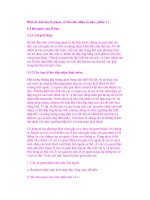
Several membranes, such as a product from Celgard made from polypropylene, have been
identified as possible candidates (see Figure 2-10).
13
Figure 2-10 Scanning electron microscope photograph of a micro porous membrane (Patent
Pending, Celgard product literature)
(Photos used with permission from Celgard, LLC)
The DEVap cooling core (Figure 2–11) is an idealized implementation of the air flows. A higher
performing air flow configuration (Figure 2–12) shows the cooling device split into two distinct
areas and depicts the air flow channels from the top vantage point. The mixed ventilation air and
return air enter from the bottom and exit at the top. The location of the desiccant drying section
is shown in green; the location of the evaporative post cooling is shown in blue. Using OA to
cool the dehumidification section improves the design by enabling higher air flow rates to
provide more cooling. Thus, the left half of the exhaust channel (Figure 2–11) is replaced by an
OA stream that flows into the page (Exhaust Airflow #1). The deep cooling of the indirect
evaporative cooler section requires a dry cooling sink; thus, some dry supply air is siphoned off
(5%–30% under maximum cooling load) to provide this exhaust air stream (Exhaust Airflow #2).
This section is placed in a counterflow arrangement to maximize the use of this air stream. This
is essential because it has been dried with desiccant, and thus has a higher embodied energy than
unconditioned air. The result is that the temperature of supply air is limited by its dew point and
will come out between 55°–75°F depending on how much is siphoned off. Combined with the
desiccant’s variable drying ability, the DEVap A/C system controls sensible and latent cooling
independently and thus has a variable SHR between < 0 (latent cooling with some heating done)
and 1.0.
14
Mixed air flow
Exhaust air flow
OA at:
T
wb
=
65
°–80°F
Exhaust
air flow #1
Exhaust
air flow #2
Desiccant
Dehumidification
Indirect
Evaporative
Post Cooling
Supply air flow at:
T
dp
=
50°–55°F
Figure 2-11 DEVap HMX air flows
The DEVap core is only half of a complete air conditioner. Figure 2-12 depicts how the DEVap
cooling core enhances the already developed LDAC technology and converts it from a dedicated
outdoor air system to an air conditioner that performs space temperature and humidity control
and provides all the necessary ventilation air. In fact, DEVap can be configured to provide 30%–
100% ventilation air. Furthermore, DEVap does not require a cooling tower, which reduces its
maintenance requirements.
15
Figure 2-12 DEVap enhancement for LDAC
2.4 DEVap Cooling Performance
Because the drying process creates sufficiently dry air, the evaporative process is no longer a
function of climate. Therefore, DEVap will work in all climates, whether hot and humid or hot
and dry. Its most challenging operational condition is at a peak Gulf Coast condition (Figure
2-13) (typical of Tampa, Florida, and Houston, Texas). In this example, DEVap mixes 70%
return air with 30% OA, resulting in a 30% ventilation rate. The mixed air stream is first
dehumidified to 51°F dew point. Then the post-evaporative cooler decreases the temperature to
59°F and uses 30% of the mixed air flow. The result is that the supply and return air flows are
equal, as are as the OA and EA flows. The system provides 7 Btu/lb of total cooling and 11.5
Btu/lb to the mixed air stream (7 Btu/lb of space cooling is equivalent to 380 cfm/ton). This is a
critical design parameter that is acceptable in the HVAC industry to provide air that is of proper
temperature and sufficiently low air volume delivery. This is all done while providing an SHR
of 0.6 to the space. Simply by decreasing the post-cooling, the SHR can be lowered further to
the necessary level. This is more critical when the ambient conditions impose a much lower
16
Psychrometric Chart at 0 ft Elevation (1.013 bar)
(14.7 psia)
SHR onto the building. An example of such a condition would be a cool April day when it is
65°–70°F and raining.
Psychrometric Chart at 0 ft Elevation (14.7 psia)
30 40 50 60 70 80 90 100 110 120
Twb = 81.3 deg F
Twb = 70.2 deg F
Twb = 64.5 deg F
Twb = 62.7 deg F
Twb = 54.1 deg F
Enthalpy = 44.9 BTU/lbm
Enthalpy = 34.1 BTU/lbm
Enthalpy = 29.5 BTU/lbm
Enthalpy = 28.2 BTU/lbm
Enthalpy = 22.6 BTU/lbm
Return Air
Outdoor Air
Mixed Air
1st Stage Air
Supply Air
Space Cooling:
7 BTU/lb
380 CFM/ton
175
150
125
100
75
50
25
0
ω (grains/lb)
Dry Bulb Temperature (°F)
Figure 2-13 DEVap cooling process in a typical Gulf Coast design condition
At the condition shown, the combined energy DEVap uses results in a total cooling source level
COP of 1.4. This assumes the 30% ventilation air can be credited toward the cooling load and
the regenerator latent COP is 1.2, a conservative value. If no ventilation air can be credited, the
source COP is 0.85. As OA humidity drops (shown at 77°F dew point), the source COP
increases. At the point where the ambient dew point drops below about 55°F, the desiccant can
be turned off and no further thermal energy is required. This simplistic explanation indicates that
as the climate becomes dryer (regardless of OA temperature), DEVap efficiency improves. As
the sensible load decreases, DEVap uses less EA to provide sensible cooling. The balanced EA
and OA result in less OA and less moisture removal by the regeneration system.
2.5 DEVap Implementation
2.5.1 New and Retrofit Residential
A 3-ton DEVap A/C cooling core is expected to be about 18 in. deep and have a 20-in. × 20-in.
frontal area if made square (see Section 3.1). This imposes no significant packaging problems in
a residential sized A/C system. DEVap air flow rate and cooling delivery are designed to match
exactly DX A/C (at 7 Btu/lb), thus the return and supply air duct design will work well.
However, DEVap conditions the space air and rejects heat to the atmosphere, so air to and from
the ambient air must be brought to the DEVap device, either by placing the DEVap cooling cores
close to the outside, or by ducting these air streams. This requirement makes implementing
DEVap different than standard DX A/C.
17
18
The regenerator for a 3-ton DEVap A/C contains a 30-kBtu boiler (compared to today’s on-
demand water heaters, which are about 200 kBtu) and a 50-cfm, 1-ft
3
HMX scavenging
regenerator. These two main components comprise the bulk of the regenerator, so the packaging
is very small and can be accommodated in many spaces, including:
• Outside (the regenerator contains no freeze-prone liquids)
• Next to the DEVap and furnace
• Next to the domestic hot water tank.
The regenerator uses natural gas or thermal heat and a standard 15 Amp, 120-V electrical
connection. The DEVap core can be integrated with the furnace and air handler, if there is one.
Figure 2-14 illustrates a possible configuration for a DEVap A/C installed in a typical U.S. home.
The regenerator component is powered by thermal sources such as natural gas and solar thermal
heat.
Figure 2-14 Example diagram of a residential installation of DEVap A/C showing the solar option
(green lines represent desiccant flows)
In a home application, DEVap performs the following functions:
• Air conditioner with independent temperature and humidity control
• Dedicated dehumidifier
• Mechanical ventilator
Ventilation air
Cool, dry air
DEVap A/C
Two stage
Regenerator
DHW
Desiccant
Storage
Return
air
Exhaust air
Optional Solar Thermal Collectors
2.5.2 New and Retrofit Commercial
In a commercial application, DEVap performs all the same functions of a DX A/C system. The
most common commercial cooling implementation is the rooftop unit (RTU). Figure 2–15
illustrates how a packaged DEVap RTU (which is expected to be smaller) may be implemented.
The DEVap core is marginally bigger than a DX evaporator coil; however, the regenerator is
compact. There is no large DX condenser section in a DEVap RTU. The DEVap RTU air flows
will integrate with the building much like a standard RTU, and will impose no significant change
in the installation and ducting process. As with the residential unit, the DEVap unit will supply
air at 380 or less cfm/ton.
Humid
Two stage
Regenerator
DEVap A/C
Desiccant
Storage
Exhaust Air
Outdoor
Ventilation Air
Return Air
Natural Gas
Supply Air
Figure 2-15 Example diagram of a packaged DEVap A/C
Figure 2–16 illustrates how a DEVap RTU would be installed on a commercial building
application. The thermal sources for regeneration could again come from natural gas or solar
thermal heat. However, the commercial application also opens the door to use waste heat from a
source such as on-site CHP. The figure illustrates many options for heat sources, with many
possible scenarios. Three possibilities are:
• Natural gas only
• CHP with or without natural gas backup
• Solar heat with or without natural gas backup.
19
Solar Thermal Collectors
DEVap RTUs
CHP with Desiccant
Regeneration
Figure 2-16 Example diagram of a commercial installation of DEVap A/C showing the solar and
CHP options
(green lines represent desiccant flows)
DEVap can be installed in buildings that contain central air handlers, similarly to a residential
installation. However, for commercial buildings, this type of installation would be highly
variable in scope and heat sources for regeneration, and is not discussed in this report. The
examples are intended to inform a knowledgeable A/C designer enough to extrapolate to
different scenarios.
20