GasTurbine Engineering HandbookSecond Edition phần 3 pptx
Bạn đang xem bản rút gọn của tài liệu. Xem và tải ngay bản đầy đủ của tài liệu tại đây (1016.07 KB, 82 trang )
//INTEGRA/B&H/GTE/FINAL (26-10-01)/CHAPTER 4.3D ± 149 ± [141±177/37] 29.10.2001 3:57PM
ASME, Performance Test Code on Overall Plant Performance,
ASME PTC 46 1996
This code is written to establish the overall plant performance. Power plants,
which produce secondary energy output such as cogeneration facilities are
included within the scope of this code. For cogeneration facilities, there is no
requirement for a minimum percentage of the facility output to be in the form
of electricity; however, the guiding principles, measurement methods, and
calculation procedures are predicated on electricity being the primary output.
As a result, a test of a facility with a low proportion of electric output may not
be capable of meeting the expected test uncertainties of this code. This code
provides explicit procedures for the determination of power plant thermal
performance and electrical output. Test results provide a measure of the
performance of a power plant or thermal island at a specified cycle configur-
ation, operating disposition and/or fixed power level, and at a unique set of base
reference conditions. Test results can then be used as defined by a contract for
the basis of determination of fulfillment of contract guarantees. Test results
can also be used by a plant owner, for either comparison to a design number,
or to trend performance changes over time of the overall plant. The results of
a test conducted in accordance with this code will not provide a basis for
comparing the thermoeconomic effectiveness of different plant design.
Power plants are comprised of many equipment components. Test data
required by this code may also provide limited performance information for
some of this equipment; however, this code was not designed to facilitate
simultaneous code level testing of individual equipment. ASME PTCs, which
address testing of major power plant equipment provide a determination of
the individual equipment isolated from the rest of the system. PTC 46 has
been designed to determine the performance of the entire heat-cycle as an
integrated system. Where the performance of individual equipment operat-
ing within the constraints of their design-specified conditions are of interest,
ASME PTCs developed for the testing of specific components should be
used. Likewise, determining overall thermal performance by combining the
results of ASME code tests conducted on each plant component is not an
acceptable alternative to a PTC 46 test.
ASME, Performance Test Code on Test Uncertainty:
Instruments and Apparatus PTC 19.1 1988
This test code specifies procedures for evaluation of uncertainties in
individual test measurements, arising from both random errors and system-
atic errors, and for the propagation of random and systematic uncertainties
Performance and Mechanical Standards 149
//INTEGRA/B&H/GTE/FINAL (26-10-01)/CHAPTER 4.3D ± 150 ± [141±177/37] 29.10.2001 3:57PM
into the uncertainty of a test results. The various statistical terms involved
are defined. The end result of a measurement uncertainty analysis is to
provide numerical estimates of systematic uncertainties, random uncertain-
ties, and the combination of these into a total uncertainty with an approxi-
mate confidence level. This is especially very important when computing
guarantees in plant output and plant efficiency.
ASME, Performance Test Code on Gas Turbines, ASME PTC 22 1997
The object of the code is to detail the test to determine the power output
and thermal efficiency of the gas turbine when operating at the test condi-
tions, and correcting these test results to standard or specified operating and
control conditions. Procedures for conducting the test, calculating the
results, and making the corrections are defined.
The code provides for the testing of gas turbines supplied with gaseous or
liquid fuels (or solid fuels converted to liquid or gas prior to entrance to the gas
turbine). Test of gas turbines with water or steam injection for emission control
and/or power augmentation are included. The tests can be applied to gas
turbines in combined-cycle power plants or with other heat recovery systems.
Meetings should be held with all parties concerned as to how the test will
be conducted and an uncertainty analysis should be performed prior to the
test. The overall test uncertainty will vary because of the differences in the
scope of supply, fuel(s) used, and driven equipment characteristics. The code
establishes a limit for the uncertainty of each measurement required; the
overall uncertainty is then calculated in accordance with the procedures
defined in the code and by ASME PTC 19.1.
Mechanical Parameters
Some of the best standards from a mechanical point of view have been
written by the American Petroleum Institute (API) and the American
Society of Mechanical Engineers, as part of their mechanical equipment
standards. The ASME and the API mechanical equipment standards are
an aid in specifying and selecting equipment for general petrochemical use.
The intent of these specifications is to facilitate the development of high-
quality equipment with a high degree of safety and standardization. The
user's problems and experience in the field are considered in writing these
specifications. The task force, which writes the specifications, consists of
members from the user, the contractor, and the manufacturers. Thus, the
task-force team brings together both experience and know-how.
150 Gas Turbine Engineering Handbook
//INTEGRA/B&H/GTE/FINAL (26-10-01)/CHAPTER 4.3D ± 151 ± [141±177/37] 29.10.2001 3:57PM
The petroleum industry is one of the largest users of gas turbines as prime
movers for drives of mechanical equipment and also for power generation
equipment. Thus the specifications written are well suited for this industry,
and the tips of operation and maintenance apply for all industries. This
section deals with some of the applicable API and ASME standards for the
gas turbine and other various associated pieces.
It is not the intent here to detail the API or ASME standards, but to
discuss some of the pertinent points of these standards and other available
options. It is strongly recommended that the reader obtain from ASME and
API all mechanical equipment standards.
API Std 616, Gas Turbines for the Petroleum, Chemical, and Gas Industry
Services, 4th Edition, August 1998
This standard covers the minimum requirements for open, simple, and
regenerative-cycle combustion gas turbine units for services of mechanical
drive, generator drive, or process gas generation. All auxiliary equipment
required for starting and controlling gas turbine units, and for turbine
protection is either discussed directly in this standard or referred to in this
standard through references to other publications. Specifically, gas turbine
units that are capable of continuous service firing gas or liquid fuel or both
are covered by this standard. In conjunction with the API specifications the
following ASME codes also supply significant data in the proper selection
of the gas turbine.
ASME Basic Gas Turbines B 133.2 Published: 1977
(Reaffirmed Year: 1997)
This standard presents and describes features that are desirable for the
user to specify in order to select a gas turbine that will yield satisfactory
performance, availability, and reliability. The standard is limited to a con-
sideration of the basic gas turbine including the compressor, combustion
system, and turbine.
ASME Gas Turbine Fuels B 133.7M Published: 1985
(Reaffirmed Year: 1992)
Gas turbines may be designed to burn either gaseous or liquid fuels, or
both with or without changeover while under load. This standard covers
both types of fuel.
Performance and Mechanical Standards 151
//INTEGRA/B&H/GTE/FINAL (26-10-01)/CHAPTER 4.3D ± 152 ± [141±177/37] 29.10.2001 3:57PM
ASME Gas Turbine Control and Protection Systems B133.4 Published:
1978 (Reaffirmed Year: 1997)
The intent of this standard is to cover the normal requirements of the
majority of applications, recognizing that economic trade-offs and reli-
ability implications may differ in some applications. The user may desire
to add, delete, or modify the requirements in this standard to meet his
specific needs, and he has the option of doing so in his own bid specifica-
tion. The gas turbine control system shall include sequencing, control,
protection, and operator information, which shall provide for orderly and
safe start-up of gas turbine, control of proper loading, and an orderly
shutdown procedure. It shall include an emergency shutdown capability,
which can be operated automatically by suitable failure detectors or
which can be operated manually. Coordination between gas turbine con-
trol and driven equipment must be provided for startup, operation, and
shutdown.
ASME Gas Turbine Installation Sound Emissions B133.8 Published:
1977 (Reaffirmed Year: 1989)
This standard gives methods and procedures for specifying the sound
emissions of gas turbine installations for industrial, pipeline, and utility
applications. Included are practices for making field sound measurements
and for reporting field data. This standard can be used by users and manu-
facturers to write specifications for procurement, and to determine com-
pliance with specification after installation. Information is included, for
guidance, to determine expected community reaction to noise.
ASME Measurement of Exhaust Emissions from Stationary Gas
Turbine Engines B133.9 (Published: 1994)
This standard provides guidance in the measurement of exhaust emissions
for the emissions performance testing (source testing) of stationary gas
turbines. Source testing is required to meet federal, state, and local environ-
mental regulations. The standard is not intended for use in continuous
emissions monitoring although many of the online measurement methods
defined may be used in both applications. This standard applies to engines
that operate on natural gas and liquid distillate fuels. Much of this standard
also will apply to engines operated on special fuels such as alcohol, coal gas,
residual oil, or process gas or liquid. However, these methods may require
152 Gas Turbine Engineering Handbook
//INTEGRA/B&H/GTE/FINAL (26-10-01)/CHAPTER 4.3D ± 153 ± [141±177/37] 29.10.2001 3:57PM
modification or be supplemented to account for the measurement of exhaust
components resulting from the use of a special fuel.
ASME Procurement Standard for Gas Turbine Electrical Equipment
B133.5 (Published: 1978) (Reaffirmed Year: 1997)
The aim of this standard is to provide guidelines and criteria for specifying
electrical equipment, other than controls, which may be supplied with a gas
turbine. Much of the electrical equipment will apply only to larger generator
drive installations, but where applicable this standard can be used for other
gas turbine drives. Electrical equipment described here, in almost all cases, is
covered by standards, guidelines, or recommended practices documented
elsewhere. This standard is intended to supplement those references and
point out the specific areas of interest for a gas turbine application. For a
few of the individual items, no other standard is referenced for the entire
subject, but where applicable a standard is referenced for a sub-item. A user
is advised to employ this and other more detailed standards to improve his
specification for a gas turbine installation. In addition, regulatory require-
ments such as OSHA and local codes should be considered in completing the
final specification. Gas turbine electrical equipment covered by this
standard is divided into four major areas: Main Power System, Auxiliary
Power System, Direct Current System, Relaying. The main power system
includes all electrical equipment from the generator neutral grounding
connection up to the main power transformer or bus but not including a
main transformer or bus. The auxiliary power system is the gas turbine
section AC supply and includes all equipment necessary to provide such
station power as well as motors utilizing electrical power. The DC system
includes the battery and charger only. Relaying is confined to electric
system protective relaying that is used for protection of the gas turbine
station itself.
ASME Procurement Standard for Gas Turbine Auxiliary Equipment
B133.3 (Published: 1981) (Reaffirmed Year: 1994)
The purpose of this standard is to provide guidance to facilitate the
preparation of gas turbine procurement specifications. It is intended for
use with gas turbines for industrial, marine, and electric power applications.
The standard also covers auxiliary systems such as lubrication, cooling, fuel
(but not its control), atomizing, starting, heating-ventilating, fire protection,
cleaning, inlet, exhaust, enclosures, couplings, gears, piping, mounting,
painting, and water and steam injection.
Performance and Mechanical Standards 153
//INTEGRA/B&H/GTE/FINAL (26-10-01)/CHAPTER 4.3D ± 154 ± [141±177/37] 29.10.2001 3:57PM
API Std 618, Reciprocating Compressors for Petroleum, Chemical, and
Gas Industry Services, 4th Edition, June 1995
This standard could be adapted to the fuel compressor for the natural gas
to be brought up to the injection pressure required for the gas turbine. Covers
the minimum requirements for reciprocating compressors and their drivers
used in petroleum, chemical, and gas industry services for handling process
air or gas with either lubricated or nonlubricated cylinders. Compressors
covered by this standard are of moderate-to-low speed and in critical
services. The nonlubricated cylinder types of compressors are used for inject-
ing fuel in gas turbines at the high pressure needed. Also covered are related
lubricating systems, controls, instrumentation, intercoolers, after-coolers,
pulsation suppression devices, and other auxiliary equipment.
API Std 619, Rotary-Type Positive Displacement Compressors for
Petroleum, Chemical, and Gas Industry Services, 3rd Edition, June 1997
The dry helical lobe rotary compressors nonlubricated cylinder types of
compressors are used for injecting of the fuel in gas turbines at the high
pressure needed. The gas turbine application requires that the compressor be
dry. This standard is primarily intended for compressors that are in special
purpose application and covers the minimum requirements for dry helical lobe
rotary compressors used for vacuum, pressure, or both in petroleum, chemical,
and gas industry services. This edition also includes a new inspector's checklist
and new schematics for general purpose and typical oil systems.
API Std 613 Special Purpose Gear Units for Petroleum, Chemical, and
Gas Industry Services, 4th Edition, June 1995
Gears, wherever used, can be a major source of problem and downtime.
This standard specifies the minimum requirements for special-purpose,
enclosed, precision, single- and double-helical one- and two-stage speed
increasers and reducers of parallel-shaft design for refinery services. Primar-
ily intended for gears that are in continuous service without installed spare
equipment. These standards apply for gears used in the power industry.
API Std 677, General-Purpose Gear Units for Petroleum, Chemical, and
Gas Industry Services, 2nd Edition, July 1997 (Reaffirmed March 2000)
This standard covers the minimum requirements for general-purpose,
enclosed single- and multi-stage gear units incorporating parallel-shaft
154 Gas Turbine Engineering Handbook
//INTEGRA/B&H/GTE/FINAL (26-10-01)/CHAPTER 4.3D ± 155 ± [141±177/37] 29.10.2001 3:57PM
helical and right angle spiral bevel gears for the petroleum, chemical, and gas
industries. Gears manufactured according to this standard are limited to the
following pitchline velocities: helical gears shall not exceed 12,000 feet per
minute 60 meters per second (60 meters per second) and spiral bevel gears
shall not exceed 8,000 feet per minute 40 meters per second (40 meters per
second). This standard includes related lubricating systems, instrumentation,
and other auxiliary equipment. Also included in this edition is new material
related to gear inspection.
API Std 614, Lubrication, Shaft-Sealing, and Control-Oil Systems
and Auxiliaries for Petroleum, Chemical, and Gas Industry Services,
4th Edition, April 1999
Lubrication, besides providing lubrication, also provides cooling for vari-
ous components of the turbine. This standard covers the minimum require-
ments for lubrication systems, oil-type shaft-sealing systems, and control-oil
systems for special-purpose applications. Such systems may serve compres-
sors, gears, pumps, and drivers. The standard includes the systems' com-
ponents, along with the required controls and instrumentation. Data sheets
and typical schematics of both system components and complete systems are
also provided. Chapters include general requirements, special purpose oil
systems, general purpose oil systems and dry gas seal module systems. This
standard is well written and the tips detailed are good practices for all types
of systems.
API Std 671, Special Purpose Couplings for Petroleum Chemical
and Gas Industry Services, 3rd Edition, October 1998
This standard covers the minimum requirements for special purpose
couplings intended to transmit power between the rotating shafts of two
pieces of refinery equipment. These couplings are designed to accommodate
parallel offset, angular misalignment, and axial displacement of the shafts
without imposing excessive mechanical loading on the coupled equipment.
ANSI/API Std 670 Vibration, Axial-Position, and Bearing-Temperature
Monitoring Systems, 3rd Edition, November 1993
Provides a purchase specification to facilitate the manufacture, procure-
ment, installation, and testing of vibration, axial position, and bearing
temperature monitoring systems for petroleum, chemical, and gas industry
services. Covers the minimum requirements for monitoring radial shaft
Performance and Mechanical Standards 155
//INTEGRA/B&H/GTE/FINAL (26-10-01)/CHAPTER 4.3D ± 156 ± [141±177/37] 29.10.2001 3:57PM
vibration, casing vibration, shaft axial position, and bearing temperatures. It
outlines a standardized monitoring system and covers requirements for
hardware (sensors and instruments), installation, testing, and arrangement.
Standard 678 has been incorporated into this edition of standard 670. This is
well-documented, standard, and widely used in all industries.
Application of the Mechanical Standards to the Gas Turbine
An examination of the above standards as they apply to the gas turbine
and its auxiliaries are further examined in this section. The ASME B 133.2
basic gas turbines and the API standard 616, gas turbines for the petroleum,
chemical, and gas industry services are intended to cover the minimum
specifications necessary to maintain a high degree of reliability in an open-
cycle gas turbine for mechanical drive, generator drive, or hot-gas genera-
tion. The standard also covers the necessary auxiliary requirements directly
or indirectly by referring to other listed standards.
The standards define terms used in the industry and describe the basic
design of the unit. It deals with the casing, rotors and shafts, wheels and
blades, combustors, seals, bearings, critical speeds, pipe connections and
auxiliary piping, mounting plates, weather-proofing, and acoustical treat-
ment.
The specifications call preferably for a two-bearing construction. Two-
bearing construction is desirable in single-shaft units, as a three-bearing
configuration can cause considerable trouble, especially when the center
bearing in the hot zone develops alignment problems. The preferable casing
is a horizontally split unit with easy visual access to the compressor and
turbine, permitting field balancing planes without removal of the major
casing components. The stationary blades should be easily removable with-
out removing the rotor.
A requirement of the standards is that the fundamental natural frequency
of the blade should be at least two times the maximum continuous speed,
and at least 10% away from the passing frequencies of any stationary parts.
Experience has shown that the natural frequency should be at least four
times the maximum continuous speed. Care should be exercised on units
where there is a great change in the number of blades between stages.
A controversial requirement of the specifications is that rotating blades or
labyrinths for shrouded rotating blades be designed for slight rubbing. A
slight rubbing of the labyrinths is usually acceptable, but excessive rubbing
can lead to major problems. New gas turbines use ``squealer blades'' some
manufacturers suggest using ceramic tips, but whatever is done, great care
should be exercised, or blade failure and housing damage may occur.
156 Gas Turbine Engineering Handbook
//INTEGRA/B&H/GTE/FINAL (26-10-01)/CHAPTER 4.3D ± 157 ± [141±177/37] 29.10.2001 3:57PM
Labyrinth seals should be used at all external points, and sealing pressures
should be kept close to atmospheric. The bearings can be either rolling
element bearings usually used in aero-derivative gas turbines and hydro-
dynamic bearings used in the heavier frame type gas turbines. In the area
of hydrodynamics bearings, tilting pad bearings are recommended, since
they are less susceptible to oil whirl and can better handle misalignment
problems.
Critical speeds of a turbine operating below its first critical should be at
least 20% above the operating speed range. The term commonly used for
units operating below their first critical is that the unit has a ``stiff shaft,''
while units operating above their first critical are said to have a ``flexible
shaft.'' There are many exciting frequencies that need to be considered in
a turbine. Some of the sources that provide excitation in a turbine system
are:
1. Rotor unbalance
2. Whirling mechanisms such as:
a. Oil whirl
b. Coulomb whirl
c. Aerodynamic cross coupling whirl
d. Hydrodynamic whirl
e. Hysteretic whirl
3. Blade and vane passing frequencies
4. Gear mesh frequencies
5. Misalignment
6. Flow separation in boundary layer exciting blades
7. Ball/race frequencies in antifriction bearings usually used in aero-
derivative gas turbines
Torsional criticals should be at least 10% away from the first or second
harmonics of the rotating frequency. Torsional excitations can be excited by
some of the following:
1. Start up conditions such as speed detents
2. Gear problems such as unbalance and pitch line runout
3. Fuel pulsation especially in low NO
x
combustors
The maximum unbalance is not to exceed 2.0 mils (0.051 mm) on rotors
with speeds below 4000 rpm, 1.5 mils (0.04 mm) for speeds between 4000
Â
±
8000 rpm, 1.0 mil (0.0254 mm) for speeds between 8000
Â
±12,000 rpm, and
0.5 mils (0.0127 mm) for speeds above 12,000 rpm. These requirements are to
Performance and Mechanical Standards 157
//INTEGRA/B&H/GTE/FINAL (26-10-01)/CHAPTER 4.3D ± 158 ± [141±177/37] 29.10.2001 3:57PM
be met in any plane and also include shaft runout. The following relationship
is specified by the API standard:
L
v
12000
N
r
4-1
where:
L
v
Vibration Limit mils (thousandth of an inch), or mm (mils  25:4
N Operating speed (RPM)
The maximum unbalance per plane (journal) shall be given by the follow-
ing relationships:
U
max
4W=N 4-2
where:
U
max
Residual unbalance ounce-inches (gram-millimeters)
W Journal static weight Lbs (kg)
A computation of the force on the bearings should be calculated to
determine whether or not the maximum unbalance is an excessive force.
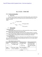
The concept of an Amplification Factor (AF) is introduced in the new
API 616 standard. Amplification factor is defined as the ratio of the critical
speed to the speed change at the root mean square of the critical amplitudes.
AF
N
c1
N
2
À N
1
4-3
Figure 4-6 is an amplitude-speed curve showing the location of the run-
ning speed to the critical speed, and the amplitude increase near the critical
speed. When the rotor amplification factor, as measured at the vibration
probe, is greater than or equal to 2.5, that frequency is called critical and
the corresponding shaft rotational frequency is called a critical speed. For the
purposes of this standard, a critically damped system is one in which the
amplification factor is less than 2.5.
Balancing requirement in the specifications require that the rotor with
blades assembled must be dynamically balanced without the coupling, but
158 Gas Turbine Engineering Handbook
//INTEGRA/B&H/GTE/FINAL (26-10-01)/CHAPTER 4.3D ± 159 ± [141±177/37] 29.10.2001 3:57PM
with the half key, if any, in place. The specifications do not discuss whether
this balancing is to be done at high-speeds or low-speeds. The balancing
conducted in most shops is at low-speed. A high-speed balancing should be
used on problem shafts, and any units, which operate above the second
critical. Field balancing requirements should be specified.
The lubrication system for the turbine is designed to provide both lubrica-
tion and cooling. It is not unusual that in the case of many gas turbines the
maximum temperatures reached in the bearing section is about 10
Â
±15 min-
utes after the unit has been shutdown. This means that the lubrication
system should continue to operate for a minimum of 20 minutes after the
turbine has been shutdown. This system closely follows the outline in API
Standard 614, which is discussed in detail in Chapter 15. Separate lubrica-
tion systems for various sections of the turbine and driven equipment may be
supplied. Many vendors and some manufacturers provide two separate
lubrication systems: One for hot bearings in the gas turbines and another
for the cool bearings of the driven compressor. These and other lubrication
systems should be detailed in the specifications.
The inlet and exhaust systems in gas turbines are described. The inlet and
exhaust systems consist of an inlet filter, silencers, ducting, and expansion
joints. The design of these systems can be critical to the overall design of a
gas turbine. Proper filtration is a must, otherwise problems of blade con-
tamination and erosion ensue. The standards are minimal for specifications,
Figure 4-6. Rotor response plot.
Performance and Mechanical Standards 159
//INTEGRA/B&H/GTE/FINAL (26-10-01)/CHAPTER 4.3D ± 160 ± [141±177/37] 29.10.2001 3:57PM
calling for a coarse metal screen to prevent debris from entering, a rain or
snow shield for protection from the elements, and a differential pressure
alarm. Most manufacturers are now suggesting so-called high-efficiency
filters that have two stages of filtration, an inertia stage to remove particles
above five microns followed by one or more filter screens, self cleaning
filters, pad type pre-filters, or a combination of them, to remove particles
below five microns. Differential pressure alarms are provided by manufac-
turers, but the trend among users has been to ignore them. It is suggested
that more attention be paid to differential pressure, than in the past, to
assure high-efficiency operation.
Silencers are also minimally specified. Work in this area has progressed
dramatically in the past few years with the NASA quiet engine program.
There are some good silencers now available on the market, and inlets can
be acoustically treated.
Starting equipment will vary, depending on the location of the unit.
Starting drives include electric motors, steam turbines, diesel engines, expan-
sion turbines, and hydraulic motors. The sizing of a starting unit will depend
on whether the unit is a single-shaft turbine or a multiple-shaft turbine with
a free-power turbine. The vendor is required to produce speed-torque curves
of the turbine and driven equipment with the starting unit torque super-
imposed. In a free-power turbine design, the starting unit has to overcome
only the torque to start the gas generator system. In a single-shaft turbine,
the starting unit has to overcome the total torque. Turning gears are recom-
mended in the specifications, especially on large units to avoid shaft bowing.
They should always be turned on after the unit has been ``brought down''
and should be kept operational until the rotor is cooled.
The gears should meet API Standard 613. Gear units should be double-
helical gears provided with thrust bearings. Load gears should be provided with
a shaft extension to permit torsional vibration measurements. On high-speed
gears, proper use of the lubricant as a coolant should be provided. Spraying oil
as a coolant on the teeth and face of the units is recommended to prevent
distortion. Chapter 14 details the design and operation characteristics of gears.
Couplings should be designed to take the necessary casing and shaft expan-
sion. Expansion is one reason for the wide acceptance of the dry flexible
coupling. A flexible diaphragm coupling is more forgiving in angular align-
ment; however, a gear-type coupling is better for axial movement access for
hot alignment checks must be provided. The couplings should be dynamically
balanced independently of the rotor system. Chapter 18 deals with the various
types of couplings and the alignment techniques for gas turbines.
Controls, instrumentation, and electrical systems in a gas turbine are
defined. The outline in the standard is the minimum a user needs for safe
160 Gas Turbine Engineering Handbook
//INTEGRA/B&H/GTE/FINAL (26-10-01)/CHAPTER 4.3D ± 161 ± [141±177/37] 29.10.2001 3:57PM
operation of a unit. More details of the instrumentation and controls are
given in Chapter 19.
The starting system can be manual, semiautomatic, or automatic, but in
all cases should provide controlled acceleration to minimum governor speed
and then, although not called for in the standards, to full speed. Units that
do not have controlled acceleration to full speed have burned out first- and
second-stage nozzles when combustion occurred in those areas instead of in
the combustor. Purging the system of the fuel after a failed start is manda-
tory, even in the manual operation mode. Sufficient time for the purging of
the system should be provided so that the volume of the entire exhaust
system has been displaced at least five times.
Alarms should be provided on a gas turbine. The standards call for alarms
to be provided to indicate malfunction of oil and fuel pressure, high exhaust
temperature, high differential pressure across the air filter, excessive vibra-
tion levels, low oil reservoir levels, high differential pressure across oil filters,
and high oil drain temperatures from the gearings. Shutdown occurs with
low oil pressure, high exhaust temperature, and combustor flameout. It is
recommended that shutdown also occur with high thrust bearing tempera-
tures and with a temperature differential in the exhaust temperature. Vibra-
tion detectors suggested in the standards are noncontacting probes.
Presently, most manufacturers provide velocity transducers mounted on
the casing, but these are inadequate. A combination of noncontacting
probes and accelerometers are needed to ensure the smooth operation and
diagnostic capabilities of the unit.
Fuel systems can cause many problems, and fuel nozzles are especially
susceptible to trouble. A gaseous fuel system consists of fuel filters, regula-
tors, and gauges. Fuel is injected at a pressure of about 60 psi (4 Bar) above
the compressor discharge pressure for which a gas compression system is
needed. Knockout drums or centrifuges are recommended, and should be
implemented to ensure no liquid carry-overs in the gaseous system.
Liquid fuels require atomization and treatment to inhibit sodium and
vanadium content. Liquid fuels can drastically reduce the life of a unit if
not properly treated. A typical fuel system is shown in Figure 4-7. The effect
of fuels on gas turbines and the details of types of fuel handling systems is
given in Chapter 12.
Recommended materials are outlined in the standards. Some of the
recommendations in the standard are carbon steel for base plates, heat-
treated forged steel for compressor wheels, heat-treated forged alloy steel
for turbine wheels, and forged steel for couplings. The growth of materials
technology has been so rapid especially in the area of high temperature
materials the standard does not deal with it. Details of some of the materials
Performance and Mechanical Standards 161
//INTEGRA/B&H/GTE/FINAL (26-10-01)/CHAPTER 4.3D ± 162 ± [141±177/37] 29.10.2001 3:57PM
technology of the high temperature alloys and single crystal blades are dealt
with in Chapters 9 and 11. However, the standards call for blading, which
must have at least 8,000 trouble-free operating hours in similar operating
conditions.
The vendor is required to present Campbell and Goodman diagrams for
the blading backed by demonstrated experience in the application of iden-
tical blades operating with the same source or frequency of excitation that is
present in the unit. The vendor shall indicate on the Goodman diagrams the
standard acceptance margins. Chapter 11 deals with the Goodman diagram
for materials. All Campbell diagrams shall show the blade frequencies that
have been corrected to reflect actual operating conditions. Where applicable,
the diagrams for shrouded blades shall show frequencies above and below
the blade lock-up speed and shall specify the speed at which blade lock-up
occurs. Chapter 5 goes into details of the Campbell diagram, and Chapter 16
deals with the types of signals emitted by the resonance of blades.
The tips of rotating blades and the labyrinths of shrouded rotating blades
shall be designed to allow the unit to start up at any time in accordance with
the vendor's requirements. When the design permits rubbing during normal
start up, the component shall be designed to be rub tolerant and the vendor
shall state in his proposal if rubbing is expected.
The blade natural frequencies shall not coincide with any source of
excitation from 10% below minimum governed speed to 10% above
Figure 4-7. Fuel systems for gas turbines.
162 Gas Turbine Engineering Handbook
//INTEGRA/B&H/GTE/FINAL (26-10-01)/CHAPTER 4.3D ± 163 ± [141±177/37] 29.10.2001 3:57PM
maximum continuous speed. If this is not feasible, blade stress levels
developed at any specified driven equipment operation shall be low enough
to allow unrestricted operation for the minimum service life. Blades shall be
designed to withstand operation at resonant frequencies during normal
warm-up. Speeds below the operation range corresponding to such blade
resonance should be clearly specified.
Excitation sources, which should be included in the Campbell diagrams,
should include fundamental and first harmonic passing frequencies of rotat-
ing and stationary blades upstream and downstream of each blade row, gas
passage splitters, irregularities in vane and nozzle pitch at horizontal casing
flanges, the first 10 rotor speed harmonics, meshing frequencies in gear units,
and periodic impulses caused by the combustor arrangement.
The turbine undergoes three basic tests, these are hydrostatic, mechan-
ical, and performance. Hydrostatic tests are to be conducted on pressure-
containing parts with water at least one-and-a-half times the maximum
operating pressure. The mechanical run tests are to be conducted for at
least a period of four hours at maximum continuous speed. This test is
usually done at no-load conditions. It checks out the bearing performance
and vibration levels as well as overall mechanical operability. It is suggested
that the user have a representative at this test to tape record as much of the
data as possible. The data are helpful in further evaluation of the unit or
can be used as base-line data. Performance tests should be conducted at
maximum power with normal fuel composition. The tests should be con-
ducted in accordance with ASME PTC-22, which is described in more
detail in Chapter 20.
Gears
This standard API Standard 613 covers special purpose gears. They are
defined as gears, which have either or both actual pinion speeds of more than
2900 rpm and pitchline velocities of more than 5000 ft/min (27 meters/sec).
The standard applies to helical gears employed in speed-reducer or speed-
increaser units.
The scope and terms used are well defined and includes a listing of
standards and codes for reference. The purchaser is required to make deci-
sions regarding gear-rated horsepower and rated input and output speeds.
This standard includes basic design information and is related to AGMA
Standard 421. Specifications for cooling water systems are given as well as
information about shaft assembly designation and shaft rotation. Gear-
rated power is the maximum power capability of the driver. Normally, the
horsepower rating for gear units between a driver and a driven unit would be
Performance and Mechanical Standards 163
//INTEGRA/B&H/GTE/FINAL (26-10-01)/CHAPTER 4.3D ± 164 ± [141±177/37] 29.10.2001 3:57PM
110% of the maximum power required by the driven unit or 110% of the
maximum power of the driver, whichever is greater.
The tooth pitting index or K factor is defined as
K
W
t
F Âd
Â
R 1
R
4-4
where:
W
t
transmitted tangential load, in pounds at the operating
pitch diameter
W
t
12; 600 Â Gear rated horse power
Pinion rpm  d
F net face width, inches
d pinion pitch diameter, inches
R ratio (number teeth in gear divided by number teeth in pinion)
The allowable K factor is given by
Allowable K Material index number/Service factor 4-5
Service factors and material index number tabulation are provided for
various typical applications, allowing the determination of the K factor.
Gear tooth size and geometry are selected so that bending stresses do not
exceed certain limits. The bending stress number is given by
S
t
Bending stress number
W
t
 P
nd
F
ÂSFÂ
1:8 cos
J
4-6
where:
W
t
as defined in Equation (4-4)
P
nd
normal diametral pitch
F net face width, inches
helix angle
J geometry factor (from AGMA 226)
SF service factor
164 Gas Turbine Engineering Handbook
//INTEGRA/B&H/GTE/FINAL (26-10-01)/CHAPTER 4.3D ± 165 ± [141±177/37] 29.10.2001 3:57PM
Design parameters on casings, joint supports, and bolting methods. Some
service and size criteria are included.
Critical speeds correspond to the natural frequencies of the gears and the
rotor bearings support system. A determination of the critical speed is made
by knowing the natural frequency of the system and the forcing function.
Typical forcing functions are caused by rotor unbalance, oil filters, misalign-
ment, and a synchronous whirl.
Gear elements must be multiplane and dynamically balanced. Where keys
are used in couplings, half keys must be in place. The maximum allowable
unbalanced force at maximum continuous speed should not exceed 10% of
static weight load on the journal. The maximum allowable residual unbalance
in the plane of each journal is calculated using the following relationship
F mr!
2
4-7
Since the force must not exceed 10% of the static journal load,
mr
0:1 W
"
!
2
4-8
Taking the correction constants, the equation can be written
Max. unbalanced force
56; 347 Â Journal static weightload
rpm
2
4-9
The double amplitude of unfiltered vibration in any plane measured on
the shaft adjacent to each radial bearing is not to exceed 2.0 mils (0.05 mm)
or the value given by
Amplitude
12;000
rpm
s
4-10
where rpm is the maximum continuous speed. It is more meaningful for gears
to be instrumented using accelerometers. Design specifications for bearings,
seals, and lubrication are also given.
Accessories such as couplings, coupling guards, mounting plates, piping,
instrumentation, and controls are described. Inspection and testing pro-
cedures are detailed. The purchaser is allowed to inspect the equipment
during manufacture after notifying the vendor. All welds in rotating parts
must receive 100% inspection. To conduct a mechanical run test, the unit
must be operated at maximum continuous speed until bearing and lube oil
Performance and Mechanical Standards 165
//INTEGRA/B&H/GTE/FINAL (26-10-01)/CHAPTER 4.3D ± 166 ± [141±177/37] 29.10.2001 3:57PM
temperatures have stabilized. Then the speed is increased to 110% of max-
imum continuous speed and run for four hours.
Lubrication Systems
This API Standard 614 standard covers the minimum requirements for
lubrication systems, oil shaft sealing systems, and related control systems for
special purpose applications. The terms are fully defined, references are well
documented and basic design is described. Details of the lubrication system
are presented in Chapter 15.
Lubrication systems should be designed to meet continuously all condi-
tions for a nonstop operation of three years. Typical lubricants should be
hydrocarbon oils with approximate viscosities of 150 SUS at 100
F
Figure 4-8. Standard oil reservoir.
166 Gas Turbine Engineering Handbook
//INTEGRA/B&H/GTE/FINAL (26-10-01)/CHAPTER 4.3D ± 167 ± [141±177/37] 29.10.2001 3:57PM
(37.8
C). Oil reservoirs should be sealed to prevent the entrance of dirt and
water and sloped at the bottom to facilitate drainage. The reservoir working
capacity should be sufficient for at least a five minute flow. A typical
reservoir is shown in Figure 4-8. The oil system should include a main oil
pump and a standby oil pump. Each pump must have its own driver sized
according to API Standard 610. Pump capacities should be based on the
systems' maximum usage plus a minimum of 15%. For seal oil systems, the
pump capacity should be maximum capacity plus 20% or 10 gpm, whichever
is greater. The standby oil pump should have an automatic startup control
to maintain safe operation if the main pump fails. Twin oil coolers should be
provided, and each should be sized to accommodate the total cooling load.
Full-flow twin oil filters should be furnished downstream of the coolers.
Filtration should be 10 microns nominal. The pressure drop for clean filters
should not exceed 5 psi (0.34 Bar) at 100
F (37.8
C) operating temperature
during normal flow.
Overhead tanks, purifiers, and degasing drums are covered. All pipe
welding is to be done according to Section IX of the ASME code, and all
piping must be seamless carbon steel, minimum schedule 80 for sizes 1
1
2
inches (38.1 mm) and smaller, and a minimum of schedule 40 for pipe sizes
2 inches (50.8 mm) or greater.
The lubrication control system should enable orderly startup, stable
operation, warning of abnormal conditions, and shutdown of main equip-
ment in the event of impending damage. A list of required alarm and shut-
down devices is provided. Figure 4-9 is a schematic of a seal lube and control
oil system. The purchaser has the right to inspect the work and testing of
subcomponents if he informs the vendor in advance. Each cooler, filter,
accumulator, and other pressure vessels should be hydrostatically tested at
one and one-half times design pressure. Cooling water jackets and other
water-handling components should be tested at one and one-half times
design pressure. The test pressure should not be less than 115 psig (7.9
Bar). Tests should be maintained for durations of at least 30 minutes.
Operational tests should:
1. Detect and correct all leaks.
2. Determine relief pressures and check for proper operation of each
relief valve.
3. Accomplish a filter cooler changeover without causing startup of the
standby pump.
4. Demonstrate that control valves have suitable capacity, response, and
stability.
5. Demonstrate the oil pressure control valve can control oil pressure.
Performance and Mechanical Standards 167
//INTEGRA/B&H/GTE/FINAL (26-10-01)/CHAPTER 4.3D ± 168 ± [141±177/37] 29.10.2001 3:57PM
Vibration Measurements
The API Standard 670 covers the minimum requirements for noncontact-
ing vibration in an axial-position monitoring system.
The accuracy for the vibration channels should meet a linearity of Æ5% of
200 millivolts per mil (0.001 inch, 0.0254 mm) sensitivity over a minimum
operating range of 80 mils (2.032 mm). For the axial position, the channel
linearity must be Æ5% of 200 millivolts per mil sensitivity and a Æ1:0 mil of
a straight line over a minimum operating range of 80 mils (2.032 mm).
Temperature should not affect the linerarity of the system by more than
5% over a temperature range of À30 to 350 8F(À34:4to176:7 8C) for the
Figure 4-9. Combined seal, lube, and control oil system.
168 Gas Turbine Engineering Handbook
//INTEGRA/B&H/GTE/FINAL (26-10-01)/CHAPTER 4.3D ± 169 ± [141±177/37] 29.10.2001 3:57PM
probe and extension cable. The oscillator demodulator is a signal condition-
ing device powered by À24 volts of direct current. It sends a radio frequency
signal to the probe and demodulates the probe output. It should maintain
linearity over the temperature range of À30 to 150
F(À34:4to65:6 8C).
The monitors and power supply should maintain their linearity over a
temperature range of À20 to 150 8F(À28:9to65:6 8C). The probes,
cables, oscillator demodulators, and power supplies installed on a single
train should be physically and electrically interchangeable.
The noncontacting vibration and axial position monitoring system, con-
sisting of probe, cables, connectors, oscillator demodulator, power supply,
and monitors. The probe tip diameters should be 0.190
Â
±0.195 inches (4.8
Â
±
4.95 mm) with body diameters of 1/4 (6.35 mm)
Â
±28 UNF À2A threaded, or
0.3
Â
±0.312 inches (7.62
Â
±7.92 mm) with a body diameter of 3/8 (9.52 mm)
À24 UNF
Â
±24A threaded. The probe length is about 1 inch long. Tests
conducted on various manufacturer's probes indicate that the 0.3
Â
±0.312-inch
(7.62
Â
±7.92 mm) probe has a better linearity in most cases. The integral probe
cables have a cover of tetra-flouroethylene, a flexible stainless steel armoring,
which extends to within four inches of the connector. The overall physical
length should be approximately 36 inches (914.4 mm) measured from probe
tip to the end of the connector. The electrical length of the probe and integral
cable should be six feet. The extension cables should be coaxial with electrical
and physical lengths of 108 inches (2743.2 mm). The oscillator demodulator
will operate with a standard supply voltage of À24 volts dc and will be
calibrated for a standard electrical length of 15 feet (5 meters). This length
corresponds to the probe integral cable and extension. Monitors should
operate from a power supply of 117 volts Æ5% with the linearity requirements
specified. False shutdown from power interruption will be prevented regard-
less of mode or duration. Power supply failure should actuate an alarm.
The radial transducers should be placed within three inches of the bearing,
and there should be two radial transducers at each bearing. Care should be
taken not to place the probe at the nodal points. The two probes should be
mounted 90
apart (Æ5
)ata45
(Æ5
) angle from each side of the vertical
center. Viewed from the drive end of the machine train, the x probe will be
on the right side of the vertical, and the y probe will be on the left side of the
vertical. Figures 4-10 and 4-11 show protection systems for a turbine and a
gear box respectively.
The axial transducers should have one probe sensing the shaft itself within
12 inches (305 mm) of the active surface of the thrust collar with the other
probe sensing the machined surface of the thrust collar. The probes should
be mounted facing in opposite directions. Temperature probes embedded in
the bearings are often more useful in preventing thrust-bearing failures than
Performance and Mechanical Standards 169
//INTEGRA/B&H/GTE/FINAL (26-10-01)/CHAPTER 4.3D ± 170 ± [141±177/37] 29.10.2001 3:57PM
the proximity probe. This is because of the expansion of the shaft casing and
the probability that the probe is located far from the thrust collar.
When designing a system for thrust bearing protection, it is necessary to
monitor small changes in rotor axial movement equal to oil film thickness.
Probe system accuracy and probe mounting must be carefully analyzed to
minimize temperature drift. Drift from temperature changes can be unac-
ceptably high.
A functional alternative to the use of proximity probes for bearing protec-
tion is bearing temperature, bearing temperature rise (bearing temperature
Figure 4-10. Typical protection system for a turbine.
170 Gas Turbine Engineering Handbook
//INTEGRA/B&H/GTE/FINAL (26-10-01)/CHAPTER 4.3D ± 171 ± [141±177/37] 29.10.2001 3:57PM
minus bearing oil temperature), and rate of change in bearing temperature.
A matrix combining these functions can produce a positive indication of
bearing distress.
A phase angle transducer should also be supplied with each train. This
transducer should record one event per revolution. Where intervening
Figure 4-11. Typical protection system for a gearbox.
Performance and Mechanical Standards 171
//INTEGRA/B&H/GTE/FINAL (26-10-01)/CHAPTER 4.3D ± 172 ± [141±177/37] 29.10.2001 3:57PM
gear-boxes are used, a mark and phase angle transducer should be provided
for each different rotational speed.
Specifications
The previous API standards are guidelines to information regarding
machine train applications. The more pertinent the information obtained
during the evaluation of the proposal, the better the selection for the prob-
lem. The following list contains items the user should consider in his attempt
to properly evaluate the bid. Some of these points are covered in the API
standards.
Table 4-2 indicates the main points an engineer must consider in evaluat-
ing different gas turbine units. Table 4-3 lists the important points that must
Table 4-2
Point to Consider in a Gas Turbine
1. Type of turbine:
2. a. Aero-derivative
2. b. Frame type
2. Type of fuel
3. Type of compressor
4. No. of stages and pressure ratio
5. Types of blades, blade attachment, and wheel attachment
6. No. of bearings
7. Type of bearings
8. Type of thrust bearings
9. Critical speed
10. Torsional criticals
11. Campbell diagrams
12. Balance planes
13. Balance pistons
14. Type of combustor
15. Wet and dry combustors
16. Types of fuel nozzles
17. Transition pieces
18. Type of turbine
19. Power transmission curvic coupling
20. No. of stages
21. Free-power turbine
22. Turbine inlet temperature
23. Type of fuels
24. Fuel additives
25. Types of couplings
26. Alignment data
table continued on next page
172 Gas Turbine Engineering Handbook
//INTEGRA/B&H/GTE/FINAL (26-10-01)/CHAPTER 4.3D ± 173 ± [141±177/37] 29.10.2001 3:57PM
Table 4-2 continued
27. Exhaust diffuser
28. Performance map of turbine and compressor
29. Gearing
30. Drawings
Accessories
1. Lubrication systems
2. Intercoolers
3. Inlet filtration system
4. Control system
5. Protection system
Table 4-3
Vendor Requirements to be Provided by the User for a Compressor Train
1. The Gas to Be Handled (Each Stream)
Composition by mol%, volume %, or weight %. To what extent does composition vary?
Corrosive effects. Limits to discharge temperature, which may cause problems with the gas.
2. Quantity to Be Handled for Each Stage
Stage quantity and unit of measurement.
If by volume, show: a. Whether wet or dry.
b. Pressure and temperature reference points.
3. Inlet Conditions for Each Stage
Barometer.
Pressure at compressor flange.
State whether gauge or absolute.
Temperature at compressor flange.
Relative humidity.
Ratio of specific heats.
Compressibility.
4. Discharge Conditions
Pressure at compressor flange.
State whether gauge or absolute.
Compressibility.
State temperature reference.
5. Interstage Conditions
Temperature difference between gas out of cooler and water into cooler.
Is there interstage removal or addition of gas?
Between what pressures may this be done? Advise permissible range.
If gas is removed, treated, and returned between stages, advise pressure loss.
What quantity change is involved?
If this changes gas composition, a resultant analysis (ratio of specific heats, relative humidity,
and compressibility at specific interstage pressure and temperature) must be provided.
6. Variable Conditions
State expected variation in intake conditionsÐpressure, temperature, relative humidity,
MW, etc.
State expected variation in discharge pressure.
table continued on next page
Performance and Mechanical Standards 173