Advanced Database Technology and Design phần 2 doc
Bạn đang xem bản rút gọn của tài liệu. Xem và tải ngay bản đầy đủ của tài liệu tại đây (448.6 KB, 56 trang )
description (e.g., in a DB) of the entities and relationships in a domain, but
this description is at a very low level in order to be efficiently processable by
the processors used. The information base is a description close to the con-
ceptual schema and is not meant to be an internal description.
Unfortunately, the term conceptual model is not always used with the
same meaning in the literature. Besides the meaning we have given to it,
other meanings we may find are these:
•
Conceptual model = conceptual schema
•
Conceptual model = conceptual schema + information base
We have chosen to use three distinct terms (conceptual model, conceptual
schema, information base) to distinguish three different concepts. The same
distinction is well established in the DB field, where we distinguish clearly
among data model (for instance, relational data model), DB schema (in some
data models), and DB (instance of a schema).
1
2.2.3 Conceptual Schema of the Behavior
Most IS domains change through time, at two levels: conceptual schema and
state. Changes at the conceptual schema level are less frequent than those at
the state level, and their origin is due to changes in users interests: For what-
ever reason, users lose interest in the representation of some entities and rela-
tionships or they want other entities and relationships to be represented in
the IS.
The most frequent changes (and the only ones we consider here) occur
at the state level. It is easily observable that the state of most IS domains
changes through time. In consequence, if the information base is a truthful
representation of that state, then the facts of the information base will need
to change through time.
An Introduction to Conceptual Modeling of Information Systems 39
1. The term information base may be confused with the term knowledge base, used in the de-
ductive DBs field, as well as in artificial intelligence. A knowledge base is a set of repre-
sentations of knowledge about a domain [11]. Normally, the language used to represent
this knowledge is the language of first-order logic. The knowledge may be simple facts,
which are represented as atomic formulas, or general knowledge about a domain, which
is represented as complex formulas. In conceptual modeling, the general knowledge
about a domain is represented in the conceptual schema, while simple facts are repre-
sented in the information base. Therefore, the correspondence is knowledge base = con-
ceptual schema + information base.
We say that there is a change in the state of the domain at time t if the
entities or relationships that exist at t are different from those existing at the
previous time. In other words, a state change is a change in the population or
one or more entity or relationship types between two states: the new state
(corresponding to t), and the old state (corresponding to t − 1).
Any change in the population of an entity (relationship) type can
always be decomposed into a set of one or more elementary changes of the
following types:
•
Insertion of entity (relationship). This change happens when there is
an entity (relationship) in the new state that did not exist in the old
state.
•
Deletion of entity (relationship). This change happens when there
was an entity (relationship) in the old state that does not exist in the
new state.
The causes of the changes are the events [3, 12]. A domain does not change
its state if no event happens. An event is any circumstance that happens at a
given instant and whose effect is a change in the domain state. Normally,
these circumstances are actions (or decisions) performed by human beings
that act on a domain (e.g., hiring an employee or making a move in a chess
game), but they also may be the result of physical processes (e.g., dropping
some amount of liquid into a tank or the rising of the sun).
It is usually assumed that events are instantaneous, that is, they do not
have duration. It is also assumed that an event causes a transition in the
domain, from an old state to a new one, without any noticeable intermediate
state. In many cases, those assumptions do not pose any particular problems.
For example, the process of hiring a new employee takes some time, but it is
likely that we are interested only in the outcome of that process: From that
moment on, the person will be an employee, which he or she was not at the
previous time.
In some cases, however, events have duration. To handle those cases in
conceptual models that require instantaneous events, it may be necessary to
refine the conceptual schema of the domain or the event itself. For example,
assume the domain includes the relationship type Is at between persons
and places. In principle, it seems natural to consider that persons are at some
place at any moment. Let us consider now the event corresponding to the
move of a person from an origin to a target. If we assume that the event
is instantaneous, then the person will continue to be at some place at any
40 Advanced Database Technology and Design
moment. But if we assume that a move is not instantaneous, then there will
be a temporal interval during which we will not know where a person is. If
we want to take into account that fact, we will need to do the following:
•
Refine the conceptual schema of the domain: now there will be
some times when we do not know where a person is.
•
Transform the move event into two events: the beginning and the
end of a move.
•
Consider that the effect of the beginning of a move is that we enter a
state in which we do not know where the moving person is.
•
Consider that the effect of the end of a move is that there is a rela-
tionship between the moving person and the target place.
For the designer, it is important to distinguish between external and gener-
ated events. An event is external if it occurs independently of the IS. If the IS
is computer-based, external events happen even if the system is out of service.
Such events are called external because they happen outside the control of the
system. The system will need to be notified of the events (to update its infor-
mation base), but the system itself has not produced the events. Many events
are external, for example, the hiring of an employee or the sunrise.
A system may know external events either by direct observation or by
users communication:
•
In direct observation, the system has some mechanism that allows it
to detect the occurrence of events. For example, a system may have a
sensor that detects the arrival of a car in a toll station.
•
In users communication, the users tell the system of the events
when they occur. For example, when a company changes the price
of a product, the system is also notified of the change.
As mentioned in Section 2.1, an IS may also have an active function. In the
active function, the users may delegate to the system the generation of some
events that change the state of the domain when some conditions hold. A
generated event is an event induced directly by the IS. Without the partici-
pation of the system, the event would not be generated, and, therefore, the
domain would not change. The system may generate an event as a response
to an explicit request from users, when it detects that the state of the domain
An Introduction to Conceptual Modeling of Information Systems 41
satisfies some condition, or because it considers the event necessary to
achieve an objective defined by the users.
Example 2.4
Assume an IS that controls an elevator. At each floor there is a button that
users can press to request the elevator. Pressing one of the buttons is an exter-
nal event. The system responds immediately by turning on the light associ-
ated with the button (to inform users that the system is aware of their
request). Turning on and off light buttons are generated events. Taking into
account the current position of the elevator, as well as the pending requests,
the system issues several commands to start or stop the motor. Those com-
mands are also generated events.
Events, either external or generated, are also instances of concepts. An
event type is a concept whose instances are events. Events may have relation-
ships with other entities. In particular, all events have a relationship with an
entity that is a time instant, which corresponds to the time when the event
happens. Figure 2.5 shows an example of the event type change of residence.
Events of this type are related with a person (who changes), a town (new resi-
dence), and a date (occurrence time).
The set of event types that exist in a domain is part of the conceptual
schema of events. The description, in some language, of that schema, as well
as other elements described next, is called the conceptual schema of the
behavior.
To be able to update the information base, the IS must know not only
the events that have happened but also their effect on the information base.
42 Advanced Database Technology and Design
Change of
residence
Person
Who
Date When
Town
Event
Where
Figure 2.5 Event type and instance.
The definition of that effect, in some language, is also part of the conceptual
schema of the behavior.
In conceptual modeling, there are several distinct ways to define the
effect of events. The most usual way consists of defining, for each event type,
an effect function that gives the new state for any old state and any instance
of the event type. For example, the effect function corresponding to the
event type change of residence, shown in Figure 2.5, might be (informally)
If an event of type change of residence, of person p and town c, occurs on
date d, then in the new state, corresponding to date d, person p will not
live any longer where she lived before, and she will be living in town c.
In the example, the effect of the event is quite limited, and the effect function
is simple. In practice, however, it is not so easy to define the effect, because
there are many event types, and some of them have a complex effect
function.
For generated events, the conceptual schema of the behavior includes
the definition of the generating conditions, that is, when the events must be
generated.
Example 2.5
Assume an IS that monitors the level of water in a tank. The system has a
sensor that detects the level of water at any time. It is expected that the sys-
tem will keep the input valve open when the water level is below a desired
minimum and closed when the level is above a desired maximum. Generated
event types are the opening and the closing of the valve. The generation con-
dition of the former could be when the current level is below the minimum
and the valve is not open already and that of the latter, when the current
level is above the maximum and the valve is not closed.
2.2.4 Integrity Constraints
The information base is a representation of the state of the domain. An IS
obtains and updates the information base from messages received through
the input interface or by direct observation of the domain.
In a perfect world, the information base would be an exact representa-
tion of the domain. Input messages would always be correct, and the system
would receive all relevant messages. Furthermore, the direct observation of
the domain would always be faithful. In a perfect world, the representation
would always be correct (or valid) and complete.
An Introduction to Conceptual Modeling of Information Systems 43
TEAMFLY
Team-Fly
®
Unfortunately, in the real world it is likely that some received messages
are incorrect, in the sense that they communicate something that is not true.
Also, the direct observation of the domain may be distorted. In such cases,
some of the facts in the information base may not be valid. It is also likely
that the system does not receive all relevant messages; then the information
base may not be complete.
Validity and completeness are the two components of the integrity
of an information base [13]. We say that an information base has integrity
when all its facts are valid and it contains all relevant facts. Integrity is an
important property of an information base. Lack of integrity normally has
negative consequences, which in some cases may be serious.
In most systems, total integrity can be achieved only by human inter-
vention. In many cases, it is necessary to check the facts in the information
base against the domain. For example, many retail stores need to check peri-
odically that the products they have on shelves correspond to their records in
the IS. It is not difficult to see that in some cases the cost of integrity is high
and hardly avoidable.
However, it is possible to build mechanisms in the IS that auto-
matically guarantee some level of integrity. We can define conditions on the
information base such that, if satisfied, we can have some level of confidence
on its integrity. These conditions, called integrity constraints, are defined in
the conceptual schema. An integrity constraint is a condition that might not
be satisfied under some circumstances, but it is understood that the IS will
include mechanisms to guarantee its satisfaction at any time.
Example 2.6
Assume that a conceptual schema has a relationship type Assigned to, involv-
ing entity types Employee and Project. Suppose that in the domain all employ-
ees are always assigned to one or more projects. An integrity constraint might
be all employees are assigned to some project. Once defined in the concep-
tual schema, we can assume that all states of the information base will con-
tain for each known employee at least one relationship with a project. The
constraint, however, does not guarantee total integrity (e.g., the information
base could have wrong assignments), but its satisfaction is a necessary
condition.
We say that an information base is consistent if it satisfies all defined
integrity constraints. We also say that a constraint is violated when the infor-
mation base does not satisfy it. When a constraint is violated, the system
must produce some response to maintain consistency. The most frequent
case is when a violation is caused by the arrival of some erroneous message,
44 Advanced Database Technology and Design
and the response is usually the rejection of the message, asking for its
correction.
Most integrity constraints refer to facts of the information base, and
then they are part of the conceptual schema of the state. Some constraints,
however, refer to events; then they are part of the conceptual schema of the
behavior. An example of the latter, which refers to events of type Birth, could
be a person cannot be parent of himself.
2.2.5 Derivation Rules
By means of the informative function, an IS provides information about the
state of the domain to users, either when they request it or under predefined
circumstances.
If an IS does not have any inference capability, it can provide only
information collected from the environment. In some cases, that may be all
that is required, but in most cases users expect that systems have some capa-
bility to infer new facts from the ones they know. A simple example is total-
ing. If we give to the system a sequence of numbers, we normally assume the
system will at least be able to compute their total.
Most ISs have some inference capability, which requires two main
components: derivation rules and an inference mechanism. Derivation rules
are defined in the conceptual schema. The inference mechanism uses deriva-
tion rules to infer new information. How the inference mechanism works
may vary from one IS to another, and it is considered to be part of the inter-
nal structure of the system; therefore, it is not specified in the conceptual
schema.
A derivation rule is an expression that defines how new facts may be
inferred from others. The concrete form of this expression depends on the
conceptual modeling language used. Often, the expressions are formulas in
a logic style, but nothing prevents the use of conventional algorithms. For
example, assume we want to define the derivation rule corresponding to the
concept grandparent from the concept parent. An expression in logic style
would be a person gp is grandparent of person gc if gp is a parent of a person
p and p is a parent of gc.
An equivalent algorithmic expression that gets the four grandparents of
person gc could be:
1. Get the two parents p1 and p2 of gc.
2. Get the two parents gp1 and gp2 of p1.
An Introduction to Conceptual Modeling of Information Systems 45
3. Get the two parents gp3 and gp4 of p2.
4. The grandparents of gc are gp1, gp2, gp3, and gp4.
Derivation rules may be specific of a given domain (e.g., a bank), applicable
to all domains of a certain class (e.g., banking), or domain independent (e.g.,
statistical concepts). The conceptual schema must include all derivation rules
that can be used in a particular system, but we should explicitly define only
those rules that are specific to our domain. The other derivation rules could
be shared by all conceptual schemas for domains of the same class or by all
conceptual schemas.
In practice, most derivation rules infer new facts of the information
base, and then the rules are included as part of the conceptual schema of the
state. However, nothing prevents the inference of events from other events,
and then the corresponding derivation rules are part of the conceptual
schema of the behavior. For example, a derivation rule referring to events of
type Travel could define Long travels as those travels such that the distance
traveled is greater than 1000 km.
2.3 Abstract Architecture of an IS
Section 2.2 presented conceptual schemas. This section shows the essential
role these schemas play in the architecture of ISs. By architecture, we mean
the main components and their relationships. In principle, there are many
possible architectures, and choosing the most convenient for a particular IS
depends on many factors, including the preferred architectural style and the
hardware and software platform on top of which it must work. However, we
do not need to take such diversity into account here. For our purposes, it will
suffice to consider the ANSI/SPARC abstract architecture proposed in the
ISO report [10] (Figure 2.6).
To illustrate this architecture and the role played by conceptual sche-
mas in it, we will use the example of a chess-playing system that can play with
persons or with other systems.
The conventional representation of the state of a chess game is a draw-
ing like the one shown in Figure 2.7. However, not everybody uses exactly
the same representation; different icons can be used to denote the same
piece. Some users may prefer other graphical representations (e.g., the three-
dimensional view), and in some cases text-based representations may be
preferred (e.g., in machine-machine communication).
46 Advanced Database Technology and Design
An external schema is a form of representation of the state of the
domain used in the domain, and an external DB is the representation of the
state of the domain in that external schema. Figure 2.7 can be considered an
external DB. External DBs are virtual, in the sense that they do not have a
physical and persistent existence within the system.
Besides a form of representation, external schemas also include aspects
of manipulation of this form, like the language used to ask queries or to
An Introduction to Conceptual Modeling of Information Systems 47
External
schema
Internal
schema
Conceptual
schema
Message
External
processor
Internal
processor
Information
processor
Information
base
External
database
Internal
database
Figure 2.6 ANSI/SPARC architecture.
Figure 2.7 A representation of the state of a chess game.
communicate external events. In the example, we again find some diversity.
There are several textual (official) and graphical ways to represent a move
(e.g., as a string, like the string D71, or by dragging a piece to the desired
place).
The result is that in general there are several external schemas for a
given domain and it is not possible to single out one that satisfies all possible
users and all possible uses. Therefore, the system must deal with several exter-
nal schemas. To do that, the system needs to know the meaning of the repre-
sentations used and the meaning of the allowed manipulations.
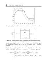
Figure 2.8 shows a simplified conceptual schema of the example. In the
figure, entity types are represented by rectangles and relationship types by
lines connecting the involved entity types. The name of the relationship type
is placed near the line, with a small filled triangle that shows the way to read
the name.
Each piece is of some type (king, queen, bishop, etc.), has a color (black
or white), and is located at some square. Squares also have a color. For clarity,
we will call board square (or just square) to a square that is part of the board,
and representation square to a square drawn in the representation of the
board (external schema). A board square is located at a row and a column,
48 Advanced Database Technology and Design
IsLocatedAt
IsLocatedAt
IsOf
Has
Has
Contains
Column
HasNumber
HasNumber
IsLocatedAt
Row
Integer
Color
Piece
PieceType
Square
Board
Figure 2.8 Conceptual schema of the chess-playing example.
which define its position in the board. Rows and columns have a number
(integer).
The conceptual schema might also include a derivation rule defining
that a board square is free if there is not a piece located at it; otherwise, it is
occupied.
There is a single conceptual schema and there may be one or more
external schemas. External schemas are defined in terms of the conceptual
schema. For instance, the correspondence between the conceptual schema in
Figure 2.8 and the external schema used in Figure 2.7 is as follows:
•
The board is represented by a (large) square, subdivided into 64
smaller representation squares corresponding to the board squares.
•
Representation squares are painted with the same color as the corre-
sponding board squares.
• Each piece has a different icon, depending on its type and color.
• If a piece p is located at a board square s, then the icon correspond-
ing to p is put over the representation square corresponding to s.
The correspondence between manipulations and the external events is
defined similarly. For example, when the user drags a piece to a representa-
tion square, the conceptual meaning is a move of that piece to the board
square where it is released.
The external processor is the architectural component that interacts with
users. In principle, there is an external processor for each external schema.
The external processors receive the messages from users (in the language of
the external schema), translate them into the language of the conceptual
schema, and forward them to the information processor.
The information processor is the component that handles the (concep-
tual) messages originated by the users and performs the active function that
may be delegated to the system. In particular, if a message communicates an
external event, then the information processor has to apply the correspond-
ing effect function and check that the resulting state is consistent. In the case
of the example, if a new move is received, the information processor has to
check whether the move is valid and, if so, to update the state of the game.
To perform those tasks, the information processor needs to access and
manipulate the state of the domain. It cannot use an external representation
because, in general, they may be partial, and, on the other hand, they include
aspects that do not have any relationship with the nature of the domain.
An Introduction to Conceptual Modeling of Information Systems 49
For example, if the system had to use the representation shown in
Figure 2.7 to check whether the move of the black queen to column 1, row 5
is valid, the information processor should check, among other things, that
the representation square in column 2 and row 6 does not have any icon over
it. Neither representation square nor icon is a relevant concept in the
domain. It is much better that the information processor may ask questions
like Is the board square of column 6 and row 2 free? where both board
square and free are defined in the conceptual schema. For similar reasons,
which will be explained, the information processor cannot use an internal
representation.
What is most natural for the information processor is to use a represen-
tation based on the conceptual schema, which is the information base. How-
ever, the information base is virtual, because it does not exist physically
within the system. When the information processor asks itself questions like
Is the board square in column 6 and row 2 free? it behaves as if the infor-
mation base really existed. In reality the question will be sent to the internal
processor, which will answer it using the physical DB.
The representation of the state that the system has to maintain internally
must allow, among other things, an efficient execution. That means the design
of the internal representation must take into account technical factors. We call
internal schema the representation form of the state of the domain used inter-
nally by the system, and internal DB the state representation in that schema.
The internal DB is the only one that has a physical existence. The internal
schema also includes the set of operations that can be invoked on the DB.
An internal schema for the system example that would be almost optimal
from the point of view of the amount of space used (although not from other
technical points of view) could be a file with the following record structure:
PieceType, Color, Row, Column
where PieceType could use one character (with a K for king, Q for queen,
R for rook, etc.), Color one bit (0: white, 1: black), and Row and Column
a single byte (number 1…8). Internal schemas, like the external ones, are
defined with respect to the conceptual schema. In the example, the corre-
spondence might be:
•
The file has a record for each piece that is on the board.
•
The first field indicates the piece type, the second its color, the third
the row number of the board square where the piece is located, and
the fourth the column number.
50 Advanced Database Technology and Design
•
The color of the board square is not represented explicitly. The
external processor may infer it by adding the numbers of the row
and the column: If the result is even, the board square is black;
otherwise, it is white.
Using that internal schema, the partial contents of the internal DB corre-
sponding to Figure 2.7 would be
R182
R184
K187
Q173
……
The internal processor receives the commands issued by the information
processor and executes them, possibly accessing the internal DB. For exam-
ple, if the internal processor receives the command (or, as in this case, ques-
tion) Is the board square of column 6 and row 2 free? it will check whether
there is a record, in the above file, such that Row = 2 and Column = 6. If
there is not such a record, the answer to the question will be positive, and
negative otherwise. To perform its task, the internal processor needs to know
the internal schema, including its correspondence with the conceptual
schema.
Modern architectures of ISs are layered, with three logical layers: pres-
entation, domain, and data management. The equivalent to the external
processors is located in the presentation layer, the information processor in
the domain layer, and the internal processor in the data management layer.
2.4 Requirements Engineering
Section 2.3 discussed the role of conceptual schemas in the architecture of
ISs. Now, we are going to see their role in the development of the systems.
Conceptual schemas are the common base for external and internal
schemas, as well as for their processors. Therefore, it is clear that it is not pos-
sible to design the architecture of an IS without the conceptual schema. Con-
ceptual modeling must precede system design.
An Introduction to Conceptual Modeling of Information Systems 51
It is important to realize that it is impossible to design a system without
knowing its conceptual schema. The only available options are either to
define explicitly the schema or to have it in the minds of the designers.
Unfortunately, sometimes the latter option is taken.
The stage that precedes system design is called requirements engineering
[14]. Its objective is to capture the requirements that must be satisfied by the
system. Normally, requirements engineering is a complex process, because
the many persons (users, designers, managers, etc.) involved in it may have
different views, needs, and interests.
Requirements engineering consists of three main phases, which can be
performed iteratively:
•
Requirements determination;
•
Requirements specification;
•
Requirements validation.
During requirements determination, the future users of the system and the
designers analyze the problems, the needs, and the domain characteristics.
On the basis of that analysis, they decide the changes to be introduced in the
domain and the functions that should be performed by a new IS. Require-
ments determination is a crucial phase, because it determines a significant
part of the final success or failure of the whole project. In this phase, it is
decided how the future system will be, and an error in the decision often
implies that users eventually will get an inadequate system.
During this phase, a conceptual schema of the existing domain may be
elaborated, if it is considered necessary to achieve a common understanding
of the domain. A conceptual schema of the desired domain can also be elabo-
rated, without determining yet the part that will correspond to the new IS.
In the requirements specification phase, the functional and nonfunc-
tional requirements of the new system are defined. The result is a set of docu-
ments (called specifications) that describe exactly the system that the users
want and that the designers have to design and build. Functional require-
ments describe what the system must do, while nonfunctional requirements
describe global properties of the system, like, for example, response time or
portability.
The conceptual schema of an IS is the specification of the functional
requirements of the system. The conceptual schema specifies all functions
(memory, informative, and active) that must be performed by the system
52 Advanced Database Technology and Design
and, together with the nonfunctional requirement specification, corresponds
to the system specification.
During requirements validation, specifications are checked with respect
to users needs. In this phase, it must be ensured that users get a complete
understanding of how the future system will be before it is built. This is
also a crucial phase that can be done well only if requirements have been
described explicitly.
Validation can be performed in two main ways:
•
By presenting the conceptual schema and in general the specifica-
tions in a language and form that is easily understood by users. If the
conceptual modeling language used is not completely understand-
able by the users, it will be necessary to provide either some help
for its interpretation or translation to more familiar languages (not
excluding natural language). When the conceptual schema is large,
as is often the case, its structuring in fragments or views may be
mandatory.
• By building (partial) prototypes of the system. If the conceptual
modeling language used is formal, then prototypes may be generated
automatically. This form of validation is usually more effective than
the other form, but in general it is more expensive.
In summary, conceptual schemas are elaborated during the require-
ments engineering stage and are the basis for the next stage, system design.
For further details on how these activities can be facilitated by comput-
ers, see Chapter 13.
2.5 Desirable Properties of Conceptual Schemas
Now that we have seen what the conceptual schemas are and their role in the
architecture of the system and during the development process, this section
describes which properties should have these schemas in order to play those
roles effectively [1517].
A well-known property of conceptual schemas is the 100% principle,or
completeness, which states that
All relevant general static and dynamic aspects, i.e., all rules, laws, etc.,
of the universe of discourse should be described in the conceptual
An Introduction to Conceptual Modeling of Information Systems 53
TEAMFLY
Team-Fly
®
schema. The information system cannot be held responsible for not
meeting those described elsewhere, including in particular those in
application programs [10].
The justification for the 100% principle is that a conceptual schema is the
definition of the general domain knowledge the IS needs to perform its func-
tions; therefore, the conceptual schema must include all required knowledge.
If we had a compiler able to generate a system from the conceptual schema,
then it would be obvious that the system could not contain anything not
included in the schema. A conceptual schema is complete if it satisfies this
property.
An important conclusion from the 100% principle is that the concep-
tual modeling language used must allow the description of all relevant aspects
of a domain.
The correctness property is complementary to the completeness prop-
erty: A conceptual schema is correct if the knowledge that defines it is true in
the domain and relevant to the functions the IS must perform. For example,
in our chess-playing system the fact that players have an address is probably
irrelevant.
The Venn diagram in Figure 2.9 shows graphically the relationship
between completeness and correctness. The left circle, A, represents the
domain knowledge the IS needs to know to perform its functions. The right
circle, C, represents the knowledge defined in the conceptual schema. In a
complete conceptual schema, A is a subset of C. In a correct conceptual
schema, C is a subset of A. In a complete and correct conceptual schema,
A = C.
54 Advanced Database Technology and Design
A
B
C
Required
knowledge
Conceptual
schema
Figure 2.9 Completeness and correctness.
Correctness and completeness of a conceptual schema are checked dur-
ing the requirements validation phase.
Another property that has become popular is the principle of conceptu-
alization, which states that
A conceptual model should only include conceptually relevant aspects,
both static and dynamic, of the universe of discourse, thus excluding
all aspects of (external or internal) data representation, physical data
organization and access as well as aspects of particular external user rep-
resentation such as message formats, data structures, etc. [10].
The justification is similar to the previous one: If a conceptual schema
is the basis for system design, then it should not include any design aspect,
thus leaving freedom to designers to decide on all those aspects. On the other
hand, when a schema focuses only on conceptual aspects, it is simpler and,
therefore, easier to be understood by users. A conceptual schema that satisfies
this principle is called design independent.
Conceptual schemas are described in some conceptual modeling lan-
guage. This language will have a set of rules that must be respected. A con-
ceptual schema is syntactically valid (or just valid) if it respects all the rules of
the language in which it is written. Syntactic correctness of a schema is inde-
pendent of the domain.
Sometimes, the same piece of knowledge about a domain may be
expressed in two or more ways in a given language. The property of simplicity
states that simple schemas must be preferred, that is, schemas that use fewer
language constructs or less complex constructs.
Closely related to the simplicity property is the property of ease of
understanding. A conceptual schema should be easily understandable by the
persons involved in the development of the IS, particularly its future users.
Section 2.4 mentioned the importance of this property during requirements
validation.
Finally, we mention the property of stability, also called flexibility,
extensibility, or modifiability. A conceptual schema is stable if small changes
in the properties of the domain or in the users requirements do not imply
large changes in the schema.
There are some proposals of metrics for evaluating these properties in
a conceptual schema (see Chapter 14). A representative example is [18].
However, this is an issue where more work needs to be done to be fully
practical.
An Introduction to Conceptual Modeling of Information Systems 55
References
[1] Langefors, B., Information Systems, Proc. IFIP 74, North Holland, 1974,
pp. 937945.
[2] Checkland, P., Systems Thinking, Systems Practice, New York: Wiley, 1981.
[3] Boman, M., et al., Conceptual Modelling, New York: Prentice-Hall, 1997.
[4] Wand, Y., and R. Weber, An Ontological Analysis of Some Fundamental Informa-
tion Systems Concepts, Proc. 9th. Intl. Conf. on Information Systems, Minneapolis,
MN, Dec. 1988, pp. 213225.
[5] Motro, A., Intensional Answers to Database Queries, IEEE Trans. on Knowledge and
Data Engineering, Vol. 6, No. 3, June 1994, pp. 444454.
[6] Papazoglou, M. P., Unraveling the Semantics of Conceptual Schemas, Comm.
ACM, Vol. 38, No. 9, Sept. 1995, pp. 8094.
[7] Ellis, J. R., Objectifying Real-Time Systems, New York: SIGS Books, 1994.
[8] Uschold, M., and M. Gruninger, Ontologies: Principles, Methods, and Applica-
tions, Knowledge Engineering Review, Vol. 11, No. 2, 1996, pp. 93136.
[9] Mylopoulos, J., Information Modeling in the Time of the Revolution, Information
Systems, Vol. 23, No. 3/4, 1998, pp. 127155.
[10] ISO/TC97/SC5/WG3, Concepts and Terminology for the Conceptual Schema and the
Information Base, J. J. Van Griethuysen (ed.), Mar. 1982.
[11] Russell, S., and P. Norvig, Artificial Intelligence: A Modern Approach, Englewood
Cliffs, NJ: Prentice-Hall, 1995.
[12] Cook, S., and J. Daniels, Designing Object Systems: Object-Oriented Modelling With
Syntropy, New York: Prentice-Hall, 1994.
[13] Motro, A., Integrity = Validity + Completeness, ACM Trans. Database Systems,
Vol. 14, No. 4, 1989, pp. 480502.
[14] Loucopoulos, P., and V. Karakostas, System Requirements Engineering, New York:
McGraw-Hill, 1995.
[15] Bubenko, J. A., Jr., Validity and Verification Aspects of Information Modeling,
Third Intl. Conf. on VLDB, Tokyo, Oct. 1977, pp. 556565.
[16] Davis, A. M., Software Requirements: Objects, Functions, and States, Englewood Cliffs,
NJ: Prentice-Hall, 1993.
[17] Lindland, O. I., G. Sindre, and A. Solvberg, Understanding Quality in Conceptual
Modeling, IEEE Software, Mar. 1994, pp. 4249.
[18] Moody, D. L., Metrics for Evaluating the Quality of Entity Relationship Models,
Proc. 17th Intl. Conf. on Conceptual Modeling, Singapore, Nov. 1998, LNCS 1507,
Springer, pp. 211225.
56 Advanced Database Technology and Design
Selected Bibliography
Batini, C., S. Ceri, and S. B. Navathe, Conceptual Database Design: An
Entity-Relationship Approach, Redwood City, CA: Benjamin/Cummings,
1992.
This book is devoted to conceptual modeling but focuses on DBs.
Nijssen, G. M., and T. A. Halpin, Conceptual Schema and Relational
Database Design, New York: Prentice-Hall, 1989.
Chapter 2 of this book (along with Chapter 4 of [14]) is an appropriate
general introduction to conceptual modeling.
Borgida, A., S. Greenspan, and J. Mylopoulos, Knowledge Representation
as the Basis for Requirements Specifications, IEEE Computer, Apr. 1985,
pp. 8291.
This article emphasizes principles with reference to languages.
Loucopoulos, P., Conceptual Modeling, in Conceptual Modeling, Data-
bases, and CASE: An Integrated View of Information Systems Development, P.
Loucopoulos and R. Zicari (eds.), New York: Wiley, 1992, pp. 126, and
Rolland, C., and C. Cauvet, Trends and Perspectives in Conceptual Model-
ing, pp. 2748 in the same book, provide a complete picture of conceptual
models and conceptual modeling languages, including many references.
Falkenberg et al., A Framework of Information System Concepts: The
FRISCO Report, IFIP WG 8.1 Task Group FRISCO, Dec. 1996.
This report is a recent in-depth treatment of IS concepts.
Boman, M., et al., Conceptual Modeling, Upper Saddle River, NJ: Prentice-
Hall, 1997.
This is one of the very few books that deals entirely with conceptual mod-
eling of information systems.
Mylopolous, J., Information Modeling in the Time of the Revolution,
Information Systems, Vol. 23, No. 3/4, 1998, pp. 127155.
This article gives a modern view of the field.
An Introduction to Conceptual Modeling of Information Systems 57
This Page Intentionally Left Blank
Part II:
Advanced Technologies
This Page Intentionally Left Blank
3
Active Databases
Oscar Díaz and Norman Paton
3.1 Introduction
DBMSs are at the heart of current IS technology. They provide reliable, effi-
cient, and effective mechanisms for storing and managing large volumes of
information in a multiuser environment. In recent years, there has been a
trend in DB research and practice toward increasing the proportion of the
semantics of an application that is supported within the DB system itself.
Temporal DBs, spatial DBs, multimedia DBs, and DB programming lan-
guages are examples of that trend. Active DBs can be considered part of this
trend, where the semantics that are supported reflect the reactive behavior of
the domain.
Traditional DBMSs are passive in the sense that commands are exe-
cuted by the DB (e.g., query, update, delete) as and when requested by the
user or the application program. However, some situations cannot be mod-
eled effectively by that pattern. As an example, consider a university DB
where data are stored about students, lecturers, timetables, bus schedules,
and so on and which is accessed by different terminals. As new students join
the school (i.e., a new tuple is inserted in the student table), the bus should
61
stop at new students addresses. Two options are available to the administra-
tor of a passive DB system who is seeking to support such a requirement.
One is to add the additional monitoring functionality to all enrollment pro-
grams so the situation is checked for each time a student is added. However,
that approach leads to the semantics of the monitoring task being distrib-
uted, replicated, and hidden among different application programs. The sec-
ond approach relies on a polling mechanism that periodically checks the
addresses of the students. Unlike the first approach, here the semantics of
the application are represented in a single place, but the difficulty stems from
ascertaining the most appropriate polling frequency. If too high, there is a
cost penalty. If too low, the reaction may be too late (e.g., the students are
left on the pavement until the polling program is run again).
An active DB would support the application by moving the reactive
behavior from the application (or polling mechanism) into the DBMS.
Active DBs are thus able to monitor and react to specific circumstances of
relevance to an application. The reactive semantics are both centralized and
handled in a timely manner.
The advantages that can be drawn from this migration are numerous
[1]. First, it promotes code reusability. Rather than replicating code in dis-
tinct applications, the code resides in a single place from which it is implicitly
invoked. Such centralization accounts for increasing consistency because no
application can bypass the policy, and maintenance is eased as changes to
the policy are localized in a single piece of code. Moreover, in a client/server
environment, centralized reactive behavior reduces network traffic, as the
reaction associated with the event is executed locally as the single implicit
invocation arises. By contrast, if the reaction were embedded within the
application, the distinct SQL statements would have been executed across
the net.
The rest of this chapter is structured as follows. Section 3.2 introduces
an example that will be used to illustrate distinct aspects of reactive behavior
through the rest of the chapter. Reactive behavior is generally supported
using rules. Rules can be seen as an implementation mechanism, but imple-
mentation must be preceded by analysis and design. Thus, Section 3.3
provides some insights on how rules can be ascertained from business poli-
cies during analysis. At design time, rules need to be described and their
behavior understood. Section 3.4 illustrates the subtleties of rule behavior
through distinct examples and presents graphical notations for rule descrip-
tion. Section 3.5 addresses implementation issues, illustrating features using
the rule system of Oracle. Finally, Section 3.6 tackles the maintenance of
rule sets.
62 Advanced Database Technology and Design
3.2 Example: University Database
This section outlines the DB that will be used later in the chapter to illustrate
the utility of active functionality. The DB stores details of a training com-
pany that provides consultancy and courses. The E/R diagram for the DB is
depicted in Figure 3.1, and the SQL create table commands for the corre-
sponding tables are provided in Figure 3.2.
Each of the entity types in the DB is represented using a table in SQL.
Because each attendee can take many courses and each course can be taken
Active Databases 63
create table employee (
name varchar(30) not null,
salary number not null,
department varchar(20) not null,
bossname varchar(20)
references employee(name),
teaches varchar(39) references course(c#),
level number,
primary key (ename));
create table room (
r# number(2) not null,
capacity number(3) not null,
heating varchar(1),
primary key (r#));
create table course
(
c# varchar(30) not null,
cname varchar(20) not null,
itsRoom number(2) references room(r#),
primary key (c#));
create table attendee (
a# varchar(30) not null,
companyProfile varchar(30) not null,
primary key (a#));
create table distribution (
theRoom number(2) not null,
theCourse varchar(30) not null,
from date,
to date,
primary key (theRoom,theCourse));
create table enrollment (
theAttendee varchar(30) not null,
theCourse varchar(30) not null,
level number,
grade number,
primary key (theAttendee,theCourse));
Figure 3.2 Tables for the example.
Employee
Attendee
Room
Course
distribution
enrollment
bossname
teaches
1:N
1:N
M:N
M:N
Figure 3.1 E/R schema for the example.
TEAMFLY
Team-Fly
®