Advanced Database Technology and Design phần 5 pptx
Bạn đang xem bản rút gọn của tài liệu. Xem và tải ngay bản đầy đủ của tài liệu tại đây (478.62 KB, 56 trang )
create the simplest, most straightforward, and easiest to maintain system. As
an individuals knowledge increases (regardless of his or her technical disci-
pline), there is a tendency to apply advanced techniques in places where they
may not be needed. Remember to always seek out the simplest way.
Another point to keep in mind is that every DB design is a balance
between maintainability and performance. Usually an increase in one yields
a decline in the other. Always bear in mind what is most important to the
client for whom you are designing a system.
6.9 The ABC Corporation Example
Now that we have examined the character of the object-relational paradigm,
let us return to ABC Corporation. Understanding what we know about the
functionality at our disposal, we can see that the telephony system can be
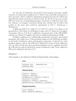
logically depicted as shown in Figure 6.2.
The hardware component is an aggregation of three principal parts.
Each part is abstractly represented as a class. For example, the server class
is the generalized representation of all servers that can be configured in the
telephony system. Figure 6.2 illustrates that there are multiple versions, or
instances, of server. These simple facts also pertain to the other hardware
components. Note that the multiple combinations for hardware parts create
multiple versions of the hardware component. The association between dif-
ferent part combinations describing unique hardware component configura-
tions is what creates the hierarchical nature of this DB example. SERVER,
MX, and NETWK represent the base classes responsible for defining the
Object-Relational Database Systems 207
Telephony system
Hardware Software
Server
Network
MX
OS
Drivers
Code
Figure 6.2 Logical representation of ABC Corporations telephony system.
class hierarchy of distinct instances. All of this also applies to how the soft-
ware component is modeled.
An interesting aspect of the software component is that multiple drivers
are needed to support a single code-operating system combination. That
leads us to understand that this is possibly a good collection-type candidate.
A good analytical understanding of this design challenge is taking place. We
have identified several opportunities for using object-relational techniques
where conventional approaches (pure relational) would have been unman-
ageable. The one challenge that has not yet been addressed is how one goes
about visualizing or modeling the object-relational model, an important fact
that has not gone unnoticed in the DB design community.
6.10 Summary
The first step in developing the object-relational DB system is understanding
the inherent strengths and weaknesses of its predecessors and combining the
most noteworthy elements into one system. The object-relational paradigm
faces a number of challenges because it must meld together characteristics of
two diametrically opposed architectures.
The first object-relational DBs met most, if not all, relational criteria
while addressing only 3050% of the object-oriented spectrum. User-
defined data typing, collection types, rudimentary support for behavior, and
some encapsulation were addressed. The most anxiously awaited features,
namely full support for inheritance, are needed to convince skeptical devel-
opers that object-oriented DBs have come into their own.
Some of the technological factors that will contribute to achieving total
object-relational character are now entering the market. Oracles release of 8i
provides full support for Java. As a matter of fact, Java is on equal ground
with PL/SQL in the DB kernel. The adoption of a true object-oriented lan-
guage is the first step in achieving the last milestone in this new paradigm.
Selected Bibliography
Anyone interested in learning more about object-relational DBs and the
techniques to model them is encouraged to read the following books:
The Unified Modeling Language User Guide, by G. Booch, J. Rumbaugh, and
I. Jacobson (Reading, MA: Addison-Wesley, 1999).
208 Advanced Database Technology and Design
An indispensable reference for anyone involved in modeling complex sys-
tems. Because UML is becoming the de facto standard for object-oriented
and now object-relational systems, this is a good choice.
High Performance Oracle8 Object-Oriented Design, by D. A. Anstey
(Scottsdale, AZ: Coriolis Group, 1998).
A good reference for understanding the technological direction that
Oracle is taking with regard to the object-relational paradigm.
Oracle8 Design Using UML Object Modeling, by P. Dorsey and J. Hudicka
(New York: McGraw-Hill, 1999).
This is the newest in object-relational references and offers good coverage
of UML modeling in Oracle8. Good real-world examples are provided along
with, as with the other titles in this list, solid information even for non-
Oracle users.
Other worthwhile references include the following:
Barker, R., CASE*METHOD Entity Relationship Modelling, Workingham,
England: Addison-Wesley, 1990.
Hunter, S. K., Cutting to the Chase, Object Magazine, Aug. 1997,
pp. 3241.
McClure, S., Object Databases Versus Object-Relational Databases, IDC
Bulletin #14821E, International Data Corp., Aug. 1997.
McFarland, G., and A. Rudmik, Object-Oriented Database Management
SystemsA Critical Review/Technology Assessment, Contract Number
F30602-89-C-0082, Rome, NY, Sept. 1993.
Object-Relational Database Systems 209
This Page Intentionally Left Blank
7
Object-Oriented Database Systems
Elisa Bertino and Esperanza Marcos
7.1 Introduction and Motivation
In spite of the fact that relational databases still hold first place in the market,
object-oriented databases are becoming more widely accepted every day.
Relational databases are suitable for traditional applications supporting man-
agement tasks such as payroll and library management. Recently, as a result
of hardware improvements, more sophisticated applications have emerged.
Engineering applications, such as computer-aided design/computer-aided
manufacturing (CAD/CAM), computer-aided software engineering (CASE),
and computer-integrating manufacturing (CIM); office automation systems;
and multimedia systems, such as GIS and medical information systems, can
be characterized as consisting of complex objects related to one another
by complex interrelationships. Representing such objects and relationships in
the relational model means that the objects must be decomposed into a large
number of tuples. A considerable number of joins are necessary to retrieve an
object when tables are too deeply nested; thus, performance is dramatically
reduced. Object-oriented databases are quite suitable to store and retrieve
complex data by allowing users to navigate through the data [1].
Another relevant problem of traditional database systems is that there
is usually a complete mismatch between the modeling constructs typical
of data models and the data structures provided by programming languages.
211
Whenever application objects need to be made persistent by storing them
in a database, a mapping is required from the programming language data
structures onto the data structures of the data model. Sometimes, such map-
ping wastes over 50% of the development time for applications and gives rise
to several program bugs [2].
The first problem can be partially solved by object-relational technol-
ogy, that is, relational systems extended with new capabilities, such as triggers
(see Chapter 3) and object-oriented capabilities (see Chapter 6). Nonethe-
less, object-relational technology is not the best solution to the impedance
mismatch problem. In addition, the difficulty in actually integrating the rela-
tional and the object-oriented models has made the market acceptance of a
common object-relational model difficult.
Object-oriented databases solve those problems by supporting complex
objects and integrating database technology with the object-oriented para-
digm. Both object-oriented databases and programming languages support
the same data model, removing the impedance mismatch of the relational
model.
This chapter reviews the state of the art in object-oriented databases by
presenting the main concepts of the object-oriented data model (Section 7.2)
and a graphical representation of an object-oriented database schema
(Section 7.3); the current standard for object-oriented database systems, the
ODMG (Section 7.4); the current state of the object-oriented database tech-
nology, with some examples in different commercial products (Section 7.5);
and finally some guidelines for object-oriented database design through an
example (Section 7.6).
7.2 Basic Concepts of the Object-Oriented Data Model
Despite the fact that the object-oriented approach is widely used today and
is characterized by large industrial efforts, there is no consolidated standard
definition of an object model. Therefore, a large number of variations can
be found when we compare the various object-oriented programming lan-
guages. Even though an object data model standard, known as the ODMG
standard [3], has been recently developed, OODBMSs are not an exception;
therefore, there is no consensus about the specific features of an object-
oriented data model. It is possible, however, to identify some basic concepts,
collectively referred to as core model. The core model is powerful enough
to satisfy many of the requirements of advanced applications and moreover
can be used as the basis for discussing the main differences with respect to
212 Advanced Database Technology and Design
conventional data models, like the relational model. It also serves as a basis
for discussing the data models of the various OODBMSs.
The core model is based on five fundamental concepts.
•
Each real-world entity is modeled by an object. Each object is associ-
ated with a unique identifier.
•
Each object has a set of instance attributes (instance variables) and
methods. The value of an attribute can be an object or a set of
objects. This characteristic allows arbitrarily complex objects to be
defined as aggregations of other objects. The set of attributes of an
object and the set of methods represent, respectively, the object
structure and the object behavior.
•
The attribute values represent the objects state. The state of an
object is accessed or modified by sending messages to the object to
invoke the corresponding methods.
• Objects sharing the same structure and behavior are grouped into
classes. A class represents a template for a set of similar objects. Each
object is an instance of some class.
• A class can be defined as a specialization of one or more classes. A
class defined as a specialization is called a subclass and inherits attrib-
utes and methods from its superclass(es).
There are many variations with respect to those five concepts, as we will
see in the remainder of this section. We use them mainly as a way to organize
the discussion rather than as a definition of the object-oriented paradigm.
An OODBMS can be defined as a DBMS that directly supports a
model based on the object-oriented paradigm. Like any DBMS, it must pro-
vide persistent storage for objects and their descriptors (schema). The system
must also provide a language for schema definition and for manipulation
of objects and their schema. In addition to those basic characteristics, an
OODBMS usually includes a query language and the necessary database
mechanisms for access optimization, such as indexing and clustering, con-
currency control and authorization mechanisms for multiuser accesses, and
recovery. The remainder of this section elaborates on the basic concepts of an
object-oriented data model.
Object-Oriented Database Systems 213
TEAMFLY
Team-Fly
®
7.2.1 Objects and Object Identifiers
In object-oriented systems, each real-world entity is uniformly represented
by an object. Each object is uniquely identified by an OID. The identity of
an object has an existence that is independent of its value. For example, the
OID for a person, Bob, is the same even if Bob changes the color of his hair
and his eyes, changes his name, changes his sex, and so on. Bob is identified
along his life by an identifier that is unique, constant along his life, and inde-
pendent of the values taken by his attributes; this identifier is the OID. As
another example, think of twins with exactly the same physical characteris-
tics: the color of their hair and their eyes, their sex, their weight, and so on.
In spite of their common attributes, they are two different objects in the real
world, and they should be the same in the database. The use of OIDs allows
objects to share subobjects and makes the construction of general object net-
works possible.
The notion of object identifier is different from the concept of key in
the relational data model. A key is defined by the value of one or more attrib-
utes and therefore can undergo modifications. By contrast, two objects are
different if they have different OIDs, even if all their attributes have the same
values. Back to the example of the twins, a possible primary key is the name,
but the name could change and even become the same for both of them.
That problem is solved by the OID.
The notion of object identity introduces at least two different notions
of equality among objects. The first, denoted here by an equals sign (=), is
the identity equality: Two objects are identity-equal, or identical, if they have
the same OID. The second, denoted here by two equals signs (==), is the
value equality: Two objects are value-equal if all their attributes that are val-
ues are equal, and all their attributes that are objects are recursively value-
equal. That is, the two objects have the same information content, even if
they have two different identifiers. Two identical objects are also value-equal,
but two value-equal objects are not necessarily identical.
Figure 7.1 shows an example of different objects that are equal. The
figure also introduces a graphical notation for objects. Each object is repre-
sented as a box, with two regions: The upper region contains the objects
OID; the second region contains the objects attributes. In the graphical rep-
resentation, we use logical OIDs, consisting of the name of the objects class
and of a numeric identifier unique within the class. For example, Window[i]
denotes the ith instance of the class Window. For each attribute, the box con-
tains the name and the value. When the value is a reference to another object,
the attribute contains the OID of the referenced object. For example, attribute
214 Advanced Database Technology and Design
title of object Window[i] contains as value the OID Title[j] to denote that
Window[i] references object Title[j]. Note that both Window[i] and Win-
dow[k] are equal; indeed, they have the same values for attributes x, y,
width, and height. Moreover, these objects reference, through the attrib-
ute title, two distinct objects, Title[j] and Title[h], which are in turn equal.
Different approaches for building OIDs can be devised. For example,
in the approach used in the Orion system [4], an OID consists of the pair
<class identifier, instance identifier>, where the first element is the identifier
of the class to which the object belongs, and the second identifies the object
within the class. The complete definition of attributes and methods for
all instances of a class is factorized and kept in an object representing the
class itself (called class-object). This approach has the major disadvantage of
making object migration from one class to another (e.g., in cases of object
reclassification) difficult, even impossible, since that would require the modi-
fication of all OIDs. Therefore, all references to migrated objects would be
invalidated. In another approach, used, for example, in the GemStone sys-
tem, the OID does not contain the class identifier. The identifier of the class
to which an object belongs in general is kept as control information stored in
the object itself.
In both previous approaches, the OID is logical, that is, it does not
contain any information about the object location on secondary storage.
Therefore, a correspondence table exists mapping OIDs onto physical
addresses. A different approach, based on physical identifiers, is used in O
2
[5], where each object is stored in a WiSS
1
record and the OID is the record
Object-Oriented Database Systems 215
Window[i]
x:2
y:3
width: 10
height: 20
title: Title[j]
Window[k]
x:2
y:3
width: 10
height: 20
title: Title[h]
Title[j]
longname: Database menu
shortname: DB
Title[h]
longname: Database menu
shortname: DB
Figure 7.1 An example of equal objects with different identifiers.
1. O
2
uses the Wisconsin Storage Subsystem (WiSS) as a storage subsystem.
identifier (RID). The RID does not change even if the record is moved to a
new page, for example, when the record grows too big for the page in which
it resides. The approach used in O
2
has the main advantage that persistent
OIDs are provided supporting a fast access to objects, since there is no need
of mapping the OID on the physical location. The major disadvantage is that
a temporary OID must be assigned to an object created on a site different
(e.g., on a workstation) from the object store site.
7.2.2 Aggregation
The values of an objects attributes can be other objects, both primitive and
nonprimitive. When the value of an attribute of an object O is a nonprimi-
tive object O′, the system stores the OID of O′ in O. When complex values
are supported by the model, the system usually stores in the object attribute
the entire complex value.
Different constructors can be used to define complex objects and val-
ues. A minimal set of constructors that should be provided by a model
includes set, list, and tuple [6]. In particular, the set constructor allows multi-
valued attributes and set objects to be defined. The list is similar to the set,
but it imposes an order on the elements. Finally, the tuple constructor is
important because it provides a natural way of modeling properties of an
object. As discussed in [6], the object constructors should be orthogonal, that
is, any constructor should be applicable to any object, including, of course,
objects constructed using any constructor whatsoever.
The notion of composite objects is found in some data models. As
already stated, a complex object may recursively reference any number of
other objects. The references, however, do not imply any special semantics
that may be of interest to different classes of applications. One important
relationship that could be superimposed on the complex object is the part-of
relationship, that is, the concept that an object is part of another object. A set
of component objects forming a single entity is a composite object. A similar
concept is found in [6], where two different types of references are defined:
general and is-part-of. The part-of relationship among objects has
some consequences on object operations. For example, if the root of a com-
posite object is removed, all component objects are deleted. Moreover, in
some models of composite objects, an object can be part of only one object,
that is, the part-of relationship imposes an exclusivity constraint. In some
systems, a lock on the root of a composite object is propagated to all the com-
ponents. Some extended relational models and object-oriented programming
languages (e.g., the Loops language) also provide the notion of composite
216 Advanced Database Technology and Design
objects. Note, however, that in some models and papers the term complex
object is used with the meaning of composite object.
7.2.3 Methods
Objects in an object-oriented database are manipulated by the use of meth-
ods. In general, a method definition consists of two components. The first
is the method signature, which specifies the method name, the names and
classes of the arguments, and the class of the result, if there is one. Some sys-
tems, like Orion [4], do not require that the class of the arguments and of
the results be declared. That happens when type checking is executed at run
time; therefore, there is no need to know that information in advance. The
second component is the method implementation, which consists of code
written in some programming language. Different OODBMSs use different
languages for method implementation. For example, both Vbase and O
2
use the C language, while Orion uses Lisp. GemStone uses OPAL, which
is nearly identical to Smalltalk. ObjectStore uses C++. In addition to the
method signature and implementation, other components may be present in
a method definition. For example, in Vbase, a method definition may specify
in addition to the base method some trigger methods and exceptions that can
be raised by the method execution.
Often in object-oriented programming languages, an object attribute
cannot be directly accessed. The only access to attributes is by invoking the
methods available at the object interface (strict encapsulation). In databases, a
lot of applications simply read or write attribute values. Queries are often
expressed as a boolean combination of predicates on attribute values. There-
fore, most OODBMSs provide direct access to attributes by means of
system-defined methods. Examples of these methods are get and set of Vbase,
which are used to read and write, respectively, a given attribute. These meth-
ods, being provided as part of the system, have an efficient implementation
and save the users from writing a large amount of trivial code. Therefore,
some systems (e.g., Vbase and the system described in [7]) allow users to
redefine the implementation of these methods for a given attribute. Each
time the attribute is accessed, the user-defined method implementation,
instead of the system-defined implementation, is invoked.
In OODBMSs characterized by distributed or client/server architec-
tures, an important architectural issue concerns the site where an invoked
method is executed. In GemStone [8], for example, the application designer
has the option of moving an object, on which a method has been invoked,
to the workstation (and then execute the method locally) or executing the
Object-Oriented Database Systems 217
method remotely on the server. A similar option is provided in the O
2
system. In general, the choice concerning the method execution site may be
complex, because different factors must be taken into account, such as the
complexity of the manipulations executed on the object, the references made
to other objects during method execution, the network bandwidth, and the
competition for the network and the server.
7.2.4 Classes and Instantiation Mechanisms
The instantiation is the first reusability mechanism (the second is inheri-
tance) in that it makes it possible to reuse the same definition to generate
objects with the same behavior and structure. Object-oriented data models
provide the concept of class as the instantiation basis. A class is an object that
acts as a template. As such, a class specifies the intended use of its instances
by defining
• A structure that is a set of instance attributes (or instance variables);
• A set of messages that define the external interface;
• A set of methods that are invoked by messages.
In this sense, the class can be viewed as a specification (intention) for its
instances. Because the class factorizes the definitions of a set of objects, it is
also an abstraction mechanism.
Given a class, it is possible to generate through the instantiation mecha-
nism objects that answer all messages defined in the class.
So far, we have implicitly assumed that an object is an instance of only
one class. However, in some models, the instances of a class C are also mem-
bers of the superclasses of C. Note that, as in [9], we distinguish between
the notions of instance of a class and member of a class. An object is
an instance of a class C if C is the most specialized class associated with the
object in a given inheritance hierarchy. An object is a member of a class C
if it is an instance of some subclass of C. Most object-oriented data models
restrict each object to be an instance of only one class, even though they
allow an object to be a member of several classes through inheritance. How-
ever, object-oriented data models [10] can be found allowing an object to be
an instance of several classes.
In addition to acting as a template, in some systems the class denotes
also the collection of all its instances, that is, its extension. That is important
because the class becomes the base on which queries are formulated. The
218 Advanced Database Technology and Design
concept of query has a meaning only if applied to sets of objects. In systems
where the class does not have this extensional function, the model provides
set constructors for object grouping. Queries are then issued on the sets
defined by the constructors. In that respect, there are differences among the
various systems (see Section 7.5).
In general, the decoupling of the intentional notion from the exten-
sional notion is correct and provides increased flexibility. The major draw-
back is that the data model becomes more complex compared to a simpler
model in which the class acts both as object template and as object extent.
7.2.5 Inheritance
The concept of inheritance is the second reusability mechanism. It allows a
class, called a subclass, to be defined starting from the definition of another
class, called the superclass. The subclass inherits the superclass attributes,
methods, and messages. In addition, a subclass may have specific attributes,
methods, and messages that are not inherited. Moreover, the subclass may
override the definition of the superclass attributes and methods. Therefore,
the inheritance mechanism allows a class to specialize another class by
additions and substitutions. Inheritance represents an important form of
abstraction, because the detailed differences of several class descriptions are
abstracted away and the commonalties factored out as a more general
superclass.
A class may have several subclasses. Some systems allow a class to have
several superclasses (multiple inheritance), while others impose the restric-
tion of a single superclass (single inheritance).
The inheritance mechanism allows the implementation of an inherited
method to be overridden in the subclass. That is accomplished by simply
defining in the subclass a method with the same name and a different imple-
mentation. Each time a message is sent to an instance of the subclass, the
implementation local to the subclass will be used to execute the method.
That results in a single name denoting different method implementations
(overloading). This unit of change (i.e., the entire method) may be, however,
too coarse, since in some situations it may be desirable to refine the object
behavior rather than completely change it. Mechanisms to accomplish that
have been proposed in the framework of object-oriented programming lan-
guages and adopted in several OODBMSs.
Often the notion of subtyping is also found in OODBMSs. It is impor-
tant, however, not to confuse inheritance with subtyping, even if there is
a unique mechanism providing both functions. For the purpose of this
Object-Oriented Database Systems 219
discussion, we briefly characterize the difference between the two concepts
as follows. Inheritance is a reusability mechanism that allows a class to be
defined from another class, by possibly extending and/or modifying the
superclass definition. Instead, a type T is a subtype of a type T ′ if an instance
of T can be used wherever an instance of T ′ is used. Therefore, subtyping is
characterized by a set of rules ensuring that no type violations occur when the
instance of a subtype T is used in place of an instance of a supertype of T.
Note that the fact that a class C is a subclass of a class C ′ does not necessarily
imply that C is also a subtype of C ′. For example, to reuse common attrib-
utes and methods (name, address, telephone, e-mail, fax, etc.), a class com-
pany can be defined as a subclass of the class person. It is obvious that, by
contrast, the company type cannot be a subtype of the person type; in such
a case, the subclassing is just a reusability mechanism. Subtyping, however,
influences inheritance, because it may restrict the overriding and impose con-
ditions on multiple inheritance, so that the subtyping rules are not violated.
An example of restriction on overriding is to require that, when the domain
of an attribute is redefined in a subclass, the domain be a subclass of the
domain associated to the attribute in the superclass. A discussion of inheri-
tance and subtyping is presented in [11].
7.3 Graphical Notation and Example
An object-oriented database schema can be represented as a graph. In such a
representation, a node (denoted by a box) represents a class. A class node
contains the names of all instance attributes and methods. The latter are
underlined. Finally, the class-attributes (and methods) are distinguished
from the instance-attributes (and methods) by enclosing them in an ellipse.
Nodes can be connected by three types of arc. An arc from class C to C ′
denotes different relationships between the two classes, depending on the arc
type. A normal arc (i.e., nonbold and nonhatched) indicates that C ′ is the
domain of an attribute A of C, or that C ′ is the domain of the result of
a method M of C. A bold arc indicates that C is the superclass of C ′.A
hatched arc indicates that C is the class of an input parameter for some
method M of C ′.
An example is presented in Figure 7.2. We assume that in the Team
class there is a method, project-budget. This method is applied to a team
and receives as input parameter a project; the method output is an integer
that represents the amount of budget allocated by the team on the project.
Moreover, we assume that a class-attribute, called maximum-salary, is
220 Advanced Database Technology and Design
defined for class Permanent. This attribute defines the maximum amount of
monthly wage that can be assigned to a permanent employee without requir-
ing special authorizations and checkings. The class-attribute maximum-
wage of class Consultant has a similar meaning.
7.4 ODMG Standard
As mentioned at the beginning of Section 7.2, there is no consolidated stan-
dard definition of an object model. Object-oriented programming languages
and object-oriented database systems support different object models. To
solve the problem, the ODMG, an organization (www.odmg.org) whose
members are producers of several various commercial OODBMSs, proposed
Object-Oriented Database Systems 221
Institute
research-area: String
institute-name: String
address
research-group*
Address
country: String
city: String
number: Integer
Team
team-name: String
industrial-sponsor
budget: Integer
staff*
: Integerproject-budget
Project
project-name: String
participants*
target: Text
: Integercost
Company
company-name: String
location
Employee
address
employee-name: String
manager
Hardware-project
devices*: String
function: String
Software-project
target-machines*: String
operating-systems*: String
Permanent
monthly-salary: Integer
status: String
maximum-salary: Integer
Consultant
daily-wage: Integer
maximum-wage: Integer
Legend
Inheritance relationship
Aggregation relationship
Input parameter relationship
Class-attribute (class-method)
Underlined names denote method names
*Multivalued attributes
Figure 7.2 A database schema example.
an object database standard. The objective of the ODMG is to unify the core
object model of the different OODBMS. Currently, the voting members of
the group are Ardent Software Inc., Ericsson, Object Design Inc., Objec-
tivity Inc., POET Software, Sun Microsystems, and Versant Corporation.
Other database vendors, such as GemStone Systems Inc., participate as
reviewers or chairs.
The first release of the standard, ODMG-93, came out in 1993 and
was revised in Release 1.1 [12]. Release 2.0 of the standard [3], which is the
last one at the time of this writing, defines an object model on the basis of
the core object model proposed by the Object Management Group (OMG).
An object definition language (ODL) supports this model. ODL is not a
full programming language but rather an independent definition language
for object specifications. The syntax of ODL extends the interface definition
language (IDL) developed by the OMG as a part of CORBA. The ODMG
standard also provides an object query language (OQL) and the C++, Small-
talk, and Java ODL bindings.
The rest of this section summarizes the main constructs that the
ODMG data model specifies and that should be supported by an
OODBMS.
7.4.1 Objects and Literals
The basic primitives are the object and the literal. Whereas objects have a
unique identifier (OID), which should be immutable, literals have no identi-
fier. Types can categorize both objects and literals.
Objects can be persistent or transient. Persistent objects, also called
database objects, continue existing once the procedure or the process that
creates them has finished. They are allocated memory and storage managed
by the OODBMS run-time system. Transient objects exist only inside the
procedure or the process that creates them. They are allocated memory
by the programming language run-time system. The lifetime of an object is
independent of the type. Some instances of the types can be persistent, while
others can be transient.
7.4.2 Types: Classes and Interfaces
A type defines the common properties (attributes and relationships) and the
behavior (operations) of a set of elements. The values of an objects proper-
ties can change at any time.
222 Advanced Database Technology and Design
A type has an external specification and one or more implementations.
The external specification is an abstract description of the type, independent
of the implementation. ODL provides the following constructs to support
the external specification: interface, class, and literal.
An interface definition is a specification that defines only the abstract
behavior of an object type. The class definition is a specification that
defines the abstract behavior and the abstract state of an object type. A
literal definition defines only the abstract state of a literal type. [3]
The implementation of an object type has to be done by a language binding.
7.4.3 Subtypes and Inheritance
The ODMG data model supports the type-subtype relationship often
referred to as an is-a relationship or a gen-spec relationship, where the
supertype is the more general type and the subtype is the more specialized
one. The ODMG data model supports two different kinds of inheritance
relationships:
•
The is-a relationship (represented by a colon) defines the inheri-
tance of behavior between object types, either interfaces or classes.
•
The EXTENDS relationship (represented by the word extend ) refers
to the inheritance of state. It applies only to object types; thus, only
classes and not literals may inherit state.
The ODMG data model supports simple inheritance and multiple
inheritance of object behavior. The EXTENDS relationship is a single
inheritance relationship between classes.
7.4.4 Extents
The extent of a type is the collection of all objects (often called instances)of
the type. It is similar to the table in a relational database. The extent defini-
tion is optional in the ODMG data model; if it is not explicitly defined, the
system will not maintain the extension.
If the type A is a subtype of B, then every instance of the type A must
also be an instance of the type B; moreover, the extent of A must be a subset
of the extent of B.
Object-Oriented Database Systems 223
TEAMFLY
Team-Fly
®
7.4.5 Keys
A key is an attribute or a set of attributes that uniquely identifies each object
of a type. This concept is similar to the candidate key of the relational model
(UNIQUE constraint in SQL), since a key attribute in the ODMG data
model prevents duplicates (uniqueness), but it allows null values (unlike the
primary key in the relational model). For a type to have a key, and given that
the scope of uniqueness is the extent of the type, the type must have an
extent.
7.4.6 Collection and Structured Types
A collection is a type that has a variable number of elements, all of which must
be of the same type. The ODMG data model supports the following collec-
tion types (objects or literals): set, bag, list, array, dictionary, and table. They
are defined by the ODMG standard as follows:
• A set is an unordered collection of elements, where no duplicates are
allowed.
•
A bag is an unordered collection of elements that may contain
duplicates.
•
A list is an ordered collection of elements.
•
An array is a dynamically sized ordered collection of elements that
can be located according to their position.
•
A dictionary is an unordered sequence of key-value pairs with no
duplicate keys.
•
A table type is a collection type defined in the ODMG data model to
express SQL tables. It is equivalent to a collection of structures.
A structured type is a type that has a fixed number of elements that may be
of different data types. The ODMG data model supports the following
structured types (objects or literals): date, interval, time, and timestamp.
These types are defined as in the ANSI SQL specification. In addition to
these types, the ODMG data model allows users to define new structured
types.
224 Advanced Database Technology and Design
7.5 Technology
This subsection briefly describes the models of three systems compliant with
the ODMG standard: GemStone, ObjectStore, and POET. These systems
have been chosen mainly because they differ in several aspects of the data
model and the query and access languages. Note, however, that, to date,
more than 20 OODBMSs are available as products. The Web sites of dif-
ferent products based on the ODMG standard are listed at the end of this
chapter.
7.5.1 GemStone
The GemStone system [8] was one of the first OODBMSs to appear on
the market. The data model and the access/manipulation language (initially
called Opal and afterward SmalltalkDB [13]) were defined as an extension of
the Smalltalk language. On closer analysis, Opal shows the features that must
be added to a programming language to make it suitable as a database lan-
guage. Applications can be written in a number of different languages,
including Smalltalk, C++, C, and Pascal. Currently, GemStone provides a
product based on Smalltalk language (called GemStone/S) and a product
based on Java language (Smalltalk/J). Latest versions integrate the Java com-
ponents with CORBA and an Object Transaction Monitor (www.gemstone.
com/products/j/main.html). We present here GemStone/S as an example of
Smalltalk-based OODBMS.
7.5.1.1 Basic Features
To illustrate the features of the GemStone/S data model, we show how the
class Institute of the example database schema in Figure 7.2 is defined:
Object subclass Institute
instVarNames: #(research-area, institute-name,
address, research-group)
classVars: #()
poolDictionary: #()
inDictionary: UserGlobals
constraints: #[#[#research-area, String],
#[#institute-name, String],
#[#address, Address],
#[#research-group, Teams]]
instanceInvariant: false
isModifiable: false.
Object-Oriented Database Systems 225
In GemStone/S, the definition of a class is always performed by sending to
the proper superclass the message subclass for which there exists a system-
defined method in each class in the database. In the above example, the class
Institute is created as a subclass of the system-class Object. In addition to the
name of the new class, a class definition message contains other arguments
describing relevant characteristics of the new class. In particular,
•
The clause instVarNames has a list of strings denoting the names
of the instance variables (i.e., attributes) of the class. Domains are
specified in the clause constraints.
•
The clause classVars has as an argument a list of class instance vari-
ables (i.e., class-attributes).
•
The clause poolDictionary has as an argument a list of pool variables
that are shared by several classes and their instances. The pool vari-
ables enable several objects, instances of different class, to share com-
mon information.
•
The clause inDictionary specifies the name of an already defined dic-
tionary, where the name of class is inserted on its creation.
•
The clause constraints specifies the domains attributes.
•
The clause instanceInvariant specifies whether the instances of the
class can be modified.
•
The clause isModifiable specifies whether the class itself can be
modified.
7.5.1.2 Methods
Methods in GemStone/S are defined by means of the message method.
This message has as an argument the name of the class to which the method
belongs and the method specification. The method specification consists of a
message pattern and a body. The message pattern is, in essence, the specifica-
tion of the method interface. Two example methods, defined for the class
Institute, are the following. The first method, when invoked on an instance
of class Institute, returns the value of attribute research-area of the
instance, whereas the second method modifies the value of attribute
research-area.
226 Advanced Database Technology and Design
method: Institute
research-area message pattern
^research-area return statement
%
method: Institute
research-area: anArea message pattern
research-area:= anArea
^self return statement
%
Note that the two methods have different message patterns. Indeed, the first
method has no input parameter, whereas the second method has one (i.e.,
the new value of attribute research-area). GemStone/S supports full encap-
sulation; therefore, a pair of methods like the preceding ones must be defined
by the users for each attribute that must be directly accessed and modified.
7.5.1.3 Object Query Language
In addition to navigation capabilities commonly provided by all
OODBMSs, GemStone/S provides a query language supporting set-oriented
queries. Queries can be issued only against set objects, not against classes. For
example, suppose that an instance of class Institute-Set has been defined hav-
ing the name an-Institute-Set and that instances of class Institute have
been added to this set. A query retrieving from the set an-Institute-Set all
institutes doing research on databases is formulated in Opal as follows:
DB-Institutes := an-Institute-Set select: {aSet |
aSet.research-area = Databases}
The result of the query is a set that is assigned to the variable DB-Institute.
Then the elements of the results can be extracted by using the usual opera-
tions on the sets. Queries may contain a boolean combination of predicates
as well as path-expression.
7.5.2 ObjectStore
The ObjectStore system has been developed starting from the C++language
as a system to provide persistency to C++ objects according to the persistent
programming language approach. In particular, ObjectStore exploits the
C++ class definition language as data definition language extending it with
Object-Oriented Database Systems 227
specific constructs for data management. In addition to the C++ based
definition language, ObjectStore currently provides interface for Java and
ActiveX. It also supports CORBA, DCOM, and JavaBeans (www.odi.com/
content/products/os/OstoreHome.html). We present here ObjectStore as an
example of C++based OODBMS.
7.5.2.1 Basic Features
The type system and the DDL in ObjectStore are based on the type system
and the class definition mechanism of C++. In particular, C++distinguishes
between objects and values, as does ObjectStore.
To illustrate the features of the ObjectStore data model, we show how
the class Institute of the example database schema in Figure 7.2 is defined:
class Institute {
public:
char* research-area;
char* name;
Address* address;
os_set<Team*> research-group;
}
In the preceding example, the public clause introduces the list of declarations
of public features (attributes and methods) of the class. Such features can
be directly accessed from outside the objects. In the example, all features
are public. The private clause, by contrast, introduces features that can be
accessed only by methods of the class.
7.5.2.2 Relationships
A further important extension of ObjectStore with respect to C++ is related
to the notion of relationship. This extension allows us to specify inverse
attributes, representing binary relationships. This functionality is requested
through the keyword inverse_member associated with an attribute and fol-
lowed by the inverse attribute name. ObjectStore automatically ensures rela-
tionship consistency. On the deletion of a participating object, the
relationship is also deleted. Thus, no dangling references can arise. It can
also be specified that the object participating in the relationship with the
deleted object must in turn be deleted. As an example, consider the schema
in Figure 7.2 and suppose that a company can be a sponsor for at most a
team and that an additional attribute, sponsor-of, having class Team as the
domain, is included in the class Company. The relationship between a team
228 Advanced Database Technology and Design
and a company corresponding to the fact that a team has a sponsor and vice
versa can be modeled by the inverse attributes industrial-sponsor in Team
and sponsor-of in Company. The relevant fragments of the definitions for
classes Team and Company are expressed in ObjectStore as follows:
class Team {
………
Company* industrial-sponsor
inverse_member Company::sponsor-of;
………}
class Company {
………
Team* sponsor-of
inverse_member Company::industrial-sponsor;
………}
Through the os_Set constructor, one-to-many and many-to-many relation-
ships can be represented as well.
7.5.3 POET
The POET system, developed by POET Software Corporation
(www.poet.com), is an extension to the C++ language that provides persis-
tence to C++objects [14]. Language extensions are limited to the declaration
syntax for persistent classes. In addition to the traditional C++ binding,
POET provides an implementation of ODMG-93 1.2 [15]. The POETs
ODMG binding is a subset of the traditional binding, so with certain limita-
tions, it is possible to mix constructs from the two application programming
interfaces (API) [16]. The next versions of POET will also provide the
ODMG ODL compiler and an ODMG Java binding. POET also imple-
ments a subset of the ODMG Object Query Language (OQL).
This section describes the technical features of the POET system; the
type system and POET data model are explained in Section 7.6.3.
7.5.3.1 Technical Features
In POET, a class is persistent if it is defined using the persistent keyword.
Every object of a persistent class has the ability to store itself in the database.
POET uses an explicit persistence model, so if a persistent object is created in
the RAM, it must be explicitly stored (applying the Assign method) to place it
in the database; moreover, deleting an object in RAM is a separate operation
Object-Oriented Database Systems 229
from deleting it from the database. Thus, manipulations of objects must be
done within a transaction.
When an object is stored in the database, POET automatically stores
the objects or data to which it refers. When an object is read from the data-
base, all references are resolved, the referenced objects or data are loaded into
memory, and the pointers are set to the appropriate RAM address. In some
cases, it would be convenient to decide when to load data and objects; POET
permits that with on-demand references (ondemand keyword).
For each declared class, the POET precompiler creates a set that holds
all objects of this class. This set is called AllSet, and it is possible to step
through the AllSet sequentially to find all objects of a given class.
Each object can exist only once in memory. Whenever a database
operation loads an object, POET first checks to see if it is already in memory.
If so, it simply returns a pointer to the existing object. Because each object
may have any number of references to itself, deleting an object cannot be
safe. POET uses a counter to keep track of the number of references made to
each object, and a call to the Forget() method will delete an object if there are
no active references to that object.
Persistent classes may contain persistent objects as embedded objects.
The embedded object may not be stored separately and does not receive an
object identity; it exists only as a member of the container object. Persistent
classes may also contain pointers or on-demand references to persistent
objects. It may also contain sets of pointers or sets of on-demand references
to persistent objects. Persistent classes may contain nonpersistent objects, but
they may not contain pointers to nonpersistent objects, because POET needs
an object identity to resolve pointers, and only persistent objects have an
OID. POET allows definition of persistent objects containing transient
members, which are not stored in the database. For instance, an object may
contain a pointer to a big image, which is needed only temporarily. The
image member may be defined as a transient member.
7.6 Object-Oriented Database Design
Previous sections have dealt with the main concepts of an object-oriented
data model, as well as the main differences with regard to the relational
model. In particular, an object-oriented data model supports many modeling
concepts and constructors, resulting in a large variety of database schema
design options. However, because of such richness, the design of an object-
oriented database schema may be difficult. For example, when should we use
230 Advanced Database Technology and Design
a certain constructor, such as the list or the array? There are many factors that
can determine the best design of a database schema. Nonetheless, it is possi-
ble to devise methodological guidelines that can help the database designer.
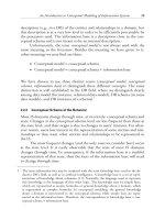
The rest of this section presents a methodological approach that sup-
ports the design of an object-oriented database schema. The approach that
we present must be understood as only a set of guidelines, because there is no
unique and exact method to design databases.
To a large extent, the object-oriented paradigm has changed the appli-
cation design process, chiefly because the gap among the various design
phases is reduced. In the same way, conceptual, logical, and implementation
models in object-oriented databases (always object models) are closer than
their corresponding models in relational databases (E/R and relational mod-
els). However, in spite of using the same paradigm in all design phases,
object-oriented conceptual models generally are richer than object-oriented
design and implementation models. Some of the concepts that are usually
supported by conceptual models, and that are not provided by most of
the design and implementation models, are: n-ary relationships, relationships
with attributes, different kinds of generalizations (such as complete/incom-
plete or disjoint/overlapping generalizations), aggregations, constraints (such
as the ordered constraint in a relationship), and so on. In addition, there are
some decisions that must be taken at design level, such as, for example, the
final representation of a multivalued attribute, because the conceptual
schema must not specify when a multivalued attribute has to be defined as an
array, as a list, or as a set.
The first step in a database design process is to define a conceptual
schema in a language (usually called model ) which has to be close to the
user and independent of the final implementation (see Chapter 1). The
model used in this step should be able to represent every users requirements;
therefore, it must be as expressive as possible. It would also be recommend-
able that the model should be supported by most of the CASE tools (see
Chapter 13). We could use the Unified Modeling Language (UML) notation
[17], which, apart from being the OMG standard notation, fulfills the previ-
ously mentioned characteristics.
Once the conceptual schema has been defined, it often can be directly
translated into the final implementation in a specific OODBMS. Another
possibility consists of getting, as an intermediate step, a schema described in
ODL [3], which would represent the design details independently of the final
product (improving portability, understandability, etc.) (see Figure 7.3). Even
though we advise getting the implementation schema in three steps (from
conceptual design to implementation design, going through the standard
Object-Oriented Database Systems 231