Advanced Database Technology and Design phần 9 pdf
Bạn đang xem bản rút gọn của tài liệu. Xem và tải ngay bản đầy đủ của tài liệu tại đây (474.64 KB, 56 trang )
performance of new components might not be possible (e.g., specialized
concurrency control for new index structures). As for the latter point, more
research is needed to fully understand the implications and side effects of
CDBMSs.
The work conducted in the area of CDBMSs has focused on extensions
in the area of new data types (including indexes useful for those nonstandard
types). Componentization of the DBMS kernel, including the transaction
manager and the query processor in general and the optimizer in particular,
has been considered less thoroughly so far. In those areas, a better under-
standing of the implications and limitations of componentization is neces-
sary. It might turn out that subsystems also need to be componentized and
that it might be possible to specialize them by adding or replacing new
(sub)components.
Despite the problems that still need to be addressed, component
DBMSs will certainly gain practical significance, and componentization of
DBMSs will continue to be a major trend in DB technology.
References
[1] Date, C. J., and H. Darwen, A Guide to the SQL Standard, 4th ed., Reading, MA:
Addison-Wesley, 1997.
[2] Bernstein, P. A., V. Hadzilacos, and N. Goodman, Concurrency Control and Recovery
in Database Systems, Reading, MA: Addison-Wesley, 1987.
[3] Codd, E., A Relational Model for Large Shared Data Banks, Comm. ACM, Vol. 13,
No. 6, 1970.
[4] Atkinson, M. P., et al., The Object-Oriented Database System Manifesto (A Political
Pamphlet), Proc. 1st Intl. Conf. on Deductive and Object-Oriented Databases, Kyoto,
Japan, Dec. 1989.
[5] Cattell, R. G. G., and D. Barry (eds.), The Object Database Standard: ODMG 2.0,
San Francisco, CA: Morgan Kaufmann, 1997.
[6] Vaskevitch, D., Database in Crisis and Transition: A Technical Agenda for the Year
2001, Proc. ACM-SIGMOD Intl. Conf. on Management of Data, Minneapolis, MN,
May 1994.
[7] Sheth, A. P., and J. A. Larson, Federated Database Systems for Managing Distrib-
uted, Heterogeneous, and Autonomous Databases, ACM Computing Surveys, Vol. 22,
No. 3, Sept. 1990.
[8] Elmagarmid, A., M. Rusinkiewicz, and A. Sheth (eds.), Management of Heterogeneous
and Autonomous Database Systems, San Francisco, CA: Morgan Kaufmann, 1999.
Component Database Systems 431
[9] Vaskevitch, D., Very Large Databases: How Large? How Different? Proc. 21st Intl.
Conf. on Very Large Data Bases (VLDB), Zurich, Switzerland, Sept. 1995.
[10] An Architecture for Database Management Standards, NBS Spec. Pub. 500-85,
Computer Corporation of America, 1982.
[11] Härder, T., and A. Reuter, Concepts for Implementing a Centralized Database Man-
agement System, Proc. Intl. Computing Symposium on Application Systems Develop-
ment, Nuernberg, Germany, Mar. 1983.
[12] Ramakrishnan, R., Database Management Systems, New York: McGraw-Hill, 1997.
[13] Astrahan, M. M., et al., System R: Relational Approach to Database Management,
ACM Trans. on Database Systems, Vol. 1, No. 2, 1976.
[14] Allen, P., and S. Frost, Component-Based Development for Enterprise Systems, New
York: Cambridge University Press, 1998.
[15] Griffel, F., Componentware, Heidelberg, Germany: Dpunkt.Verlag, 1998.
[16] Hamilton, D. (ed.), Java Beans, Version 1.01, Sun Microsystems, 1997.
[17] Krieger, D., and R. M. Adler, The Emergence of Distributed Component Plat-
forms, IEEE Computer, Vol. 31, No. 3, Mar. 1998.
[18] Nierstrasz, O., and L. Dami, Component-Oriented Software Technology, in
O. Nierstrasz and D. Tsichritzis (eds.), Object-Oriented Software Composition, London,
UK: Prentice-Hall, 1995.
[19] Nierstrasz, O., and T. D. Meijler, Beyond Objects: Components, in M. P.
Papazoglou and G. Schlageter (eds.), Cooperative Information Systems: Trends and
Directions, San Diego, CA: Academic Press, 1998.
[20] Orfali, R., D. Harkey, and J. Edwards, The Essential Client/Server Survival Guide, 2nd
ed., New York: Wiley, 1996.
[21] Perry, D. E., and A. L. Wolf, Foundations for the Study of Software Architectures,
ACM SIGSOFT Software Engineering Notes, Vol. 17, No. 4, 1992.
[22] Shaw, M., and D. Garlan, Software Architecture: Perspectives on an Emerging Discipline,
Upper Saddle River, NJ: Prentice-Hall, 1996.
[23] Geppert, A., and K. R. Dittrich, Bundling: Towards a New Construction Paradigm
for Persistent Systems, Networking and Information Systems J., Vol. 1, No. 1, June
1998.
[24] Stonebraker, M., and P. Brown, Object-Relational DBMSs, 2nd ed., San Francisco,
CA: Morgan Kaufmann, 1999.
[25] Developing DataBlade Modules for Informix Dynamic Server With Universal Data
Option, White Paper, Informix Corp., Menlo Park, CA, 1998.
[26] DB2 Relational Extenders, White Paper, IBM Corp., May 1995.
432 Advanced Database Technology and Design
[27] Oracle8 Object-Relational Data Server: The Next Generation of Database Technol-
ogy, Oracle Business White Paper, June 1997.
[28] Bliujute, R., et al., Developing a DataBlade for a New Index, Proc. 15th Intl. Conf.
on Data Engineering, Sydney, Australia, Mar. 1999.
[29] Dessloch, S., and N. M. Mattos, Integrating SQL Databases With Content-Specific
Search Engines, Proc. 23rd Intl. Conf. on Very Large Data Bases (VLDB), Athens,
Greece, Aug. 1997.
[30] Gaede, V., and O. Guenther, Multidimensional Access Methods, ACM Computing
Surveys, Vol. 30, No. 2, June 1998.
[31] Bayer, R., and M. Schkolnick, Concurrency of Operations on B-Trees, Acta Infor-
matica, Vol. 9, 1977.
[32] Kornacker, M., C. Mohan, and J. M. Hellerstein, Concurrency and Recovery in
Generalized Search Trees, Proc. ACM SIGMOD Intl. Conf. on Management of Data,
Tucson, AZ, May 1997.
[33] Blakeley, J. A., OLE DB: A Component DBMS Architecture, Proc. 12th Intl. Conf.
on Data Engineering (ICDE), New Orleans, LA, Feb./Mar. 1996.
[34] Blakeley, J. A., Data Access for the Masses Through OLE DB, Proc.
ACM-SIGMOD Intl. Conf. on Management of Data, Montreal, Canada, June 1996.
[35] OLE DB Programmers Reference: Version 1.0, Vol. 2, Microsoft Corp., July 1996.
[36] Tork Roth, M., and P. Schwarz, Dont Scrap It, Wrap It! A Wrapper Architecture for
Legacy Data Sources, Proc. 23rd Intl. Conf. on Very Large Data Bases (VLDB), Athens,
Greece, Aug. 1997.
[37] Haas, L. M., et al., Optimizing Queries Across Diverse Data Sources, Proc. 23rd
Intl. Conf. on Very Large Data Bases (VLDB), Athens, Greece, Aug. 1997.
[38] Olson, S., et al., The Sybase Architecture for Extensible Data Management, Bulletin
of the Technical Committee on Data Engineering, Vol. 21, No. 3, Sept. 1998.
[39] CORBAservices: Common Object Services Specification, The Object Management
Group, Mar. 1995.
[40] The Common Object Request Broker: Architecture and Specification, Revision 2.1,
The Object Management Group, Aug. 1997.
[41] Bernstein, P. A., and E. Newcomer, Principles of Transaction Processing for the Systems
Professional, San Francisco, CA: Morgan Kaufmann, 1996.
[42] Elmagarmid, A. K. (ed.), Database Transaction Models for Advanced Applications,
San Francisco, CA: Morgan Kaufmann, 1992.
[43] Geppert, A., and K. R. Dittrich, Strategies and Techniques: Reusable Artifacts for the
Construction of Database Management Systems, Proc. 7th Intl. Conf. on Advanced
Information Systems Engineering (CAiSE), Jyväskylä, Finland, June 1995.
Component Database Systems 433
TEAMFLY
Team-Fly
®
[44] Geppert, A., S. Scherrer, and K. R. Dittrich, KIDS: A Construction Approach for
Database Management Systems Based on Reuse, Tech. Report 97.01, Dept. of Com-
puter Science, University of Zurich, Zurich, Switzerland, Jan. 1997.
[45] Chrysanthis, P. K., and K. Ramamritham, Synthesis of Extended Transaction Mod-
els Using ACTA, ACM Trans. on Database Systems, Vol. 19, No. 3, Sept. 1994.
[46] Gueting, R. H., Second-Order Signature: A Tool for Specifying Data Models, Query
Processing, and Optimization, Proc. ACM-SIGMOD Intl. Conf. on Management of
Data, Washington, DC, May 1993.
[47] Stonebraker, M., P. Brown, and M. Herbach, Interoperability, Distributed Applica-
tions and Distributed Databases: The Virtual Table Interface, Bulletin of the Techni-
cal Committee on Data Engineering, Vol. 21, No. 3, Sept. 1998.
[48] Batini, C., S. Ceri, and S. B. Navathe, Conceptual Database Design: An Entity-
Relationship Approach, Redwood City, CA: Benjamin/Cummings, 1992.
[49] Elmasri, R., and S. B. Navathe, Fundamentals of Database Systems, 2nd ed., Redwood
City, CA: Benjamin/Cummings, 1994.
[50] Chen, P. P., The Entity-Relationship ModelTowards a Unified View of Data,
ACM Trans. on Database Systems, Vol. 1, No. 1, 1976.
[51] Booch, G., I. Jacobson, and J. Rumbaugh, The Unified Modeling Language User Guide,
Reading, MA: Addison-Wesley, 1999.
[52] ACT-NET Consortium, The Active Database Management System Manifesto: A
Rulebase of ADBMS Features, ACM SIGMOD Record, Vol. 25, No. 3, Sept. 1996.
[53] Lohman, G. M., et al., Extensions to Starburst: Objects, Types, Functions, and
Rules, Comm. ACM, Vol. 34, No. 10, 1991.
[54] Ram, S., and V. Ramesh, Schema Integration: Past, Present, and Future, in
A. Elmagarmid, M. Rusinkiewicz, and A. Sheth (eds.), Management of Heterogeneous
and Autonomous Database Systems, San Francisco, CA: Morgan Kaufmann, 1999.
[55] Batory, D. S., T. Y. Leung, and T. E. Wise, Implementation Concepts for an Exten-
sible Data Model and Data Language, ACM Trans. on Database Systems, Vol. 13,
No. 3, 1988.
[56] Biliris, A., and E. Panagos, Transactions in the Client-Server EOS Object Store,
Proc. 11th Intl. Conf. on Data Engineering, Taipei, Taiwan, Mar. 1995.
[57] Biliris, A., and E. Panagos, A High Performance Configurable Storage Manager,
Proc. 11th Intl. Conf. on Data Engineering, Taipei, Taiwan, Mar. 1995.
[58] Blakeley, J. A., Open OODB: Architecture and Query Processing Overview, in
A. Dogac, et al. (eds.), Advances in Object-Oriented Database Systems, New York:
Springer-Verlag, 1994.
[59] Blott, A., L. Relly, and H. J. Schek, An Open Abstract-Object Storage System, Proc.
ACM-SIGMOD Intl. Conf. on Management of Data, Montreal, Canada, June 1996.
434 Advanced Database Technology and Design
[60] Carey, M. J., et al., Storage Management for Objects in EXODUS, in W. Kim
and F. H. Lochovsky (eds.), Object-Oriented Concepts, Databases, and Applications,
New York: ACM Press, 1989.
[61] Carey, M. J., et al., The Architecture of the EXODUS Extensible DBMS, in K. R.
Dittrich, U. Dayal, and A. P. Buchmann (eds.), On Object-Oriented Database Systems,
New York: Springer-Verlag, 1991.
[62] Chou, H. T., et al., Design and Implementation of the Wisconsin Storage System,
SoftwarePractice and Experience, Vol. 15, No. 10, 1985.
[63] Graefe, G., and D. J. DeWitt, The EXODUS Optimizer Generator, Proc.
ACM-SIGMOD Intl. Conf. on Management of Data, San Francisco, CA, May 1987.
[64] Lindsay, B., J. McPherson, and H. Pirahesh, A Data Management Extension Archi-
tecture, Proc. ACM-SIGMOD Intl. Conf. on Management of Data, San Francisco, CA,
May 1987.
[65] Paul, H. B., et al., Architecture and Implementation of the Darmstadt Database Ker-
nel System, Proc. ACM-SIGMOD Intl. Conf. on Management of Data, San Francisco,
CA, May 1987.
[66] Stonebraker, M., Inclusion of New Types in Relational Database Systems, Proc. Intl.
Conf. on Database Systems, Los Angeles, CA, Feb. 1986.
[67] Unland, R., and G. Schlageter, A Transaction Manager Development Facility for
Non-Standard Database Systems, in A. K. Elmagarmid (ed.), Database Transaction
Models for Advanced Applications, San Mateo, CA: Morgan Kaufmann, 1992.
[68] Wells, D. L., J. A. Blakeley, and C. W. Thompson, Architecture of an Open Object-
Oriented Database Management System, IEEE Computer, Vol. 25, No. 10, 1992.
[69] Geppert, A., and K. R. Dittrich, Constructing the Next 100 Database Management
Systems: Like the Handyman or Like the Engineer? ACM SIGMOD Record, Vol. 23,
No. 1, Mar. 1994.
[70] Haas, L. M., et al., Extensible Query Processing in Starburst, Proc. ACM SIGMOD
Intl. Conf. on Management of Data, Portland, OR, May/June 1989.
Component Database Systems 435
This Page Intentionally Left Blank
Part III:
Advanced Design Issues
This Page Intentionally Left Blank
13
CASE Tools: Computer Support for
Conceptual Modeling
Mokrane Bouzeghoub, Zoubida Kedad, and Elisabeth Métais
13.1 Introduction to CASE Tools
The acronym CASE (computer-aided software engineering) implies two
aspects: software engineering and computer aid. Software engineering refers
to the activities of analysis, design, implementation, and maintenance of
information systems, to which we can add the complementary tasks of verifi-
cation, assessment, and validation of all the decisions that have been taken
and products that have been generated during the projects life cycle. Com-
puter aid concerns all the possible supports that a computer can provide to
facilitate the project management and documentation, to control the com-
plexity of a design, and to reason on the specifications and models.
CASE technology emerged in the late 1970s and early 1980s with code
generation and program testing. The success of relational DBs encouraged
the development of data dictionaries and the maintenance of design traces.
The explosion of computer graphics and workstations imposed CASE tools
by providing attractive interfaces and by opening up a new era of cooperative
distributed design and development. Evolution of traditional languages
439
from third generation to fourth generation and the success of reusable
object libraries accompanying object-oriented languages like C++ and Java
confirmed CASE tools as an advanced technology that cannot be bypassed in
the development of modern information systems.
Current CASE tools have sparse functionalities, cover different phases
in a projects life cycle, and are based on different formal specification mod-
els. This makes a comparison difficult. There is no standard architecture for a
CASE tool, only products that address specific activities in software engineer-
ing. The project actors see CASE tools from their individual perspectives and
from their own roles in the software project. Many classifications of CASE
tools have been proposed; they are either based on the projects life cycle
(analysis, design, implementation, validation, maintenance, administration,
etc.), on the level of abstraction (upper CASEs, middle CASEs, and lower
CASEs), or on the degree of automation (manual tools; semiautomated, or
interactive, tools; fully automated tools). Programming experts focus on
process modeling, formal verification of program behavior, and code genera-
tion. Database experts focus on conceptual data modeling, physical DB
design, and integrity constraints validation. Project managers focus on data
dictionaries, report generation, and assessment techniques.
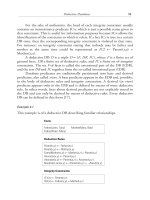
The daisy in Figure 13.1 gives a flavor of an ideal integrated CASE
toolset. The figure highlights a set of functionalities provided by CASE tools
independently of any specific methodology and classification. One can imag-
ine as many CASE environments as combinations of petals in the daisy.
Among CASE tools we can distinguish those related to project manage-
ment and control, those related to DB modeling, those related to process
modeling, and those related to IS administration and maintenance. The
baseline of these tools is the knowledge repository that groups all the meta-
data concerning the application domain, the products and the processes of
the project, and the generic reusable components. The cornerstone of the
toolset is the fundamental inference and reasoning mechanisms that can be
used by various tools. Graphical interfaces constitute a convenient way to
synthesize specifications and to give a rapid understanding of the semantics
of the system under construction.
13.1.1 Functional Classification of CASE Tools
The functional classification of tools given in Table 13.1 is not exhaustive,
but it gives a good view of the diversity of CASE tools that support software
engineering projects.
440 Advanced Database Technology and Design
13.1.1.1 Project Management Tools
Among the project management and cost evaluation tools, we can distin-
guish planning and decision support tools such as PERT diagrams, spread-
sheets, and workflows. Task assessment and product integration tools refer to
the tools that help in evaluating deliverables and consolidating their integra-
tion into intermediate or final products. Report generation maintains prog-
ress reports, cost statements, and recovery actions in case of failure or delay.
Current CASE tools for project management (e.g., Platinum Process Contin-
uum by Platinum Technology, Autoplan by Digital Tools, and MS-Project
by Microsoft) are not specific to software engineering but are taken among
CASE Tools: Computer Support for Conceptual Modeling 441
Metadata
repository
Reasoning
mechanisms
Reusable components
Quality
assurance
Testing and
validation
Project
management
Report
generators
Change
propagation
Project
planning
Project
assessment
Reverse
engineering
Physical
design
Normalization
View
integration
Conceptual
modeling
Code
generation
Knowledge
acquisition
Graphical
interface
Figure 13.1 Ideal CASE toolset.
the tools provided for any other management activity. Integration of those
tools within the software engineering environment is usually done through
the knowledge repository.
13.1.1.2 Database Design Tools
Database design tools (e.g., Designer 2000 by Oracle Corp.) are formal or
semiformal supports that help in the definition of the global DB schema and
user views. Some tools support conceptual modeling; others support logical
or physical design. Model transformation tools allow users to map schemas
of different formalisms into one pivot design model. View integration tools
reconcile different perceptions of the real world into one single consistent
schema. Database reverse engineering tools allow the extraction of data struc-
tures from legacy systems and abstract them into a logical or conceptual
schema. Database design tools are perhaps the most well-integrated tools
provided in the marketplace.
442 Advanced Database Technology and Design
Table 13.1
Functional Classification of CASE Tools
Project
Management
Tools
Database
Design Tools
Process
Modeling
Tools
Administration and
Maintenance Tools
Repository
Management
Tools
Project
planning
Conceptual
modeling
Functional
decomposition
Code inspection Knowledge
representation
Cost
evaluation
Logical design
(normalization)
Formal
specification
Database schema
evolution
Graphical editors
Product
integration
Physical design
(optimization)
Formal
verification
Report generation Textual interfaces
Task
assessment
Model
transformation
Behavior
validation
Tuning applications Cross referencing
Report
generation
DDL generation Code
generation
Tuning DB systems History
management
View
integration
Code testing Version
management
Reverse
engineering
Reverse
engineering
Impact search
13.1.1.3 Process Modeling Tools
Process modeling tools help in functional decomposition of a given system,
in the formal specification and verification of each function, and in code
generation (e.g., Developer 2000 by Oracle Corp, Pacbench by IBM). Code
testing tools are also among the oldest tools in software engineering. Because
of its complexity, reverse engineering of programs is less developed than that
of data structures. Code generation and code testing tools are probably the
most important tools whose productivity profit is the highest. Automatic
coding produces, in principle, correct programs whose maintenance is easy,
thanks to their standard way of generation and documentation. Important
problems in code generation are the definition of the input specification lan-
guage and the optimization of the generated code. Among the interesting
subproducts of automatic code generation are prototyping tools that allow
validation of user requirements and interfaces.
13.1.1.4 Maintenance and Administration Tools
Administration and maintenance tools refer to all the support that allows the
information system administrator to evolve applications by changing speci-
fications and propagating the change to the implementation, by changing
technology and migrating data and code to the new one, and by improving
performance with DB tuning or program tuning. Multiple-version manage-
ment and code inspection for errors are also among administration tools.
Administration and maintenance activities may result in inconsistencies and
inefficiencies. Decision support tools, such as simulation tools and cost esti-
mation tools, which are able to trace or evaluate the impact of a specific sys-
tem change, are valuable tools that avoid system downgrading. These kinds
of tools are called impact search tools. They are usually supplied by DB
system providers and platform providers. An example of such a tool is
Openview RPM (Hewlett-Packard), which helps in tuning the resources.
13.1.1.5 Repository and Metadata Tools
Repository management refers to a set of tools that support other CASE
functionalities. The knowledge repository is the memory of the design and
maintenance activities. It contains metadata describing DBs and processes,
cross referencing between data and processes, inputs and outputs of each
CASE tool, metamodels driving the tools, design decisions, history of
changes, trace of simulations, and so on. The repository is a common shared
memory between CASE tools and between designers and programmers. The
CASE Tools: Computer Support for Conceptual Modeling 443
TEAMFLY
Team-Fly
®
cooperative realization of a software project is organized around the knowl-
edge repository.
13.1.2 Communication Between CASE Tools
The proliferation of CASE tools has rapidly posed the problem of communi-
cation among the tools. Data dictionaries are now recognized as basements
for the construction of a software engineering environment, and most of the
provided CASE tools propose their own data dictionaries. A valuable effort
was carried out in the late 1980s for normalizing structures with the ANSI
standard, called IRDS [1]. Recent work done by OMG on unifying mod-
eling concepts and representations, proposed in UML [2], may lead to the
definition of a new generation of metadata repositories. Besides data diction-
aries, the European projects PCTE [3] and ESF [4] proposed generic proto-
cols and software bus, and CORBA [5] provided ORBs as a base technology
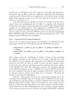
to exchange objects between different heterogeneous systems. Figure 13.2
summarizes the different approaches to cooperating CASE tools.
The next section focuses on CASE tools that help in the analysis,
design, and implementation of DBs. We highlight the fundamental knowl-
edge and reasoning mechanisms used by these tools. The purpose is to show
the internal aspects of CASE tools through their intelligent components, that
is, how they contribute to acquire application knowledge, how they structure
444 Advanced Database Technology and Design
CASE-1
CASE-n
CASE-2
CASE-3
LAN
CASE
communication
interfaces
CASE-1
CASE-3
CASE-2
CASE-n
Software bus
(e.g., CORBA)
Repository
Client
CASE-1
Data server
Common Portable
Interface (PCTE)
Software bus (CORBA)
Client/server (IRDS)
Client
CASE-2
Client
CASE-n
Client
CASE-3
Figure 13.2 Different approaches to integrate CASE tools.
that knowledge and form conceptual and logical schemas, how these are
schemas validated and transformed into low-level representations, and how
they are verified and validated. Our aim is to provide the basic ideas that gov-
ern the design and implementation of a CASE tool and to show the balance
between what a CASE tool can do and what remains the designers creativity
and decisions. We particularly insist in these sections on CASE functionali-
ties that help in solving hard problems, such as knowledge acquisition, con-
ceptual modeling, and design validation.
13.2 A CASE Framework for Database Design
Database design has been widely investigated and explored during the past
three decades. Many design frameworks have been proposed, and there is a
consensus to distinguish among four abstraction levels: external, conceptual,
logical, and physical design. Based on these levels, different modeling nota-
tions, techniques, and approaches have been proposed. Early provided design
tools support relational normalization, schema mapping between the entity-
relationship model and the relational model, and DDL generation. The early
1980s saw the promotion of expert systems and knowledge-based tools that
integrated heuristics, design alternatives, and high-level interaction with
the human designer [6]. The late 1980s confirmed the industrial use of DB
design tools; hundreds of CASE tools were proposed in the software engi-
neering market. The 1990s saw the emergence of object-oriented languages
and methodologies with their companion tools. Database design tools gained
in maturity and in complexity.
To understand the role and the contribution of these tools, we use the
framework in Figure 13.3. The framework serves as an ideal CASE environ-
ment, one that illustrates most of the possible tools related to DB design.
Knowledge acquisition concerns the collection of all the knowledge
necessary for the conceptual modeling of the DB. Knowledge acquisition is
done during user requirements analysis, either by interaction with potential
DB users, extraction of data from forms and texts, or by the use of some
appropriate graphical interface. Knowledge acquisition is driven by preexist-
ing domain knowledge, a predefined enterprise model, or any procedure that
helps in requirement analysis.
Data abstraction and structuring consist of organizing the knowledge
acquired during the acquisition phase and defining the main entities and
relationships that best capture the views of the users. That corresponds to
the effective conceptual modeling phase. Depending on the complexity of
CASE Tools: Computer Support for Conceptual Modeling 445
the target information system, the conceptual schema may either be obtained
in one shot or after the integration of several separate schemas that corre-
spond to different user views. Reverse engineering is another way to abstract
conceptual entities and relationships from existing files or DBs.
Verification checks the formal verification of the conceptual model,
and validation checks its relevance to user requirements. Formal verification
guarantees consistency, irredundancy, and completeness. Formal verification
techniques depend on the conceptual model used. Conformance with user
requirements is much harder. It is usually based on heuristics, expert rules,
and prototyping. Validation is the most powerful aid that CASE tools can
provide. Indeed, the minimum requirement expected from a CASE tool is at
least to check that the design is correct.
446 Advanced Database Technology and Design
VIEW1 VIEW2
VIEW3
Logical
schema
Conceptual
schema
Knowledge Acquisition
Graphical
interface
Natural
language
interface
Formal and
semiformal
interface
Domain and
application
knowledge
Data abstraction and structuring
Linguistic
knowledge
Technical
knowledge
Rules, dependencies
Access frequency, workload
User/designer
Verification
Physical
schema
Reverse
engineering
Reverse
engineering
View integration
Transformation and normalization
Optimization
Paraphrasing/
validation
Figure 13.3 A framework for DB design environment.
View integration or schema integration is a design approach necessary
when the complexity of the problem requires its decomposition and modular
formalization. Integration is also required in modern ISs that are built from
legacy systems or from multiple heterogeneous sources like distributed sys-
tems or Web sites. Schema integration is often completed by data integra-
tion, which deals with instances and their heterogeneous representations.
Transformation and normalization concern the multiple mappings a
schema may undergo to achieve a canonical representation or another
formalization. For example, mapping an entity-relationship schema into a
relational schema is one of the important DB design steps. Relational nor-
malization can also be considered as a mapping process from first normal
form to third or fourth normal form.
Optimization covers all the implementation and tuning decisions that
influence the performance of DB queries. Optimization cannot be done
without knowledge of all the important queries that represent the main
activity of the DB. Optimization may lead to changing physical DB schema,
introducing indexes, replicating data, reducing redundancy, and so forth.
Optimization requires a good understanding of DB system internals and
more generally the software and hardware technologies used to realize the
information system.
Our aim in the rest of this chapter is to describe, for the conceptual
and logical levels, tools that support corresponding design activities. For each
design task, we summarize the main problems to be solved and how far
CASE tools go in the automation of that task. Besides the established tech-
niques and algorithms, we will particularly examine the other design exper-
tise that can enhance CASE tools capabilities and bring them up toward the
human designer competence.
13.3 Conceptual Design Tools
Conceptual modeling covers several design activities, such as defining con-
ceptual schemas from scratch or by integrating several predefined schemas,
verifying the consistency of the schema, and validating the relevance of the
schema with respect to user expectations. This section investigates the differ-
ent CASE tools that can support those activities. Before defining the tools,
we present a reference conceptual model that will be used to describe illustra-
tive examples.
CASE Tools: Computer Support for Conceptual Modeling 447
13.3.1 The Choice of the Conceptual Model
The purpose of a conceptual schema is to describe in a formal way the part of
the real world to represent into a DB. The choice of the conceptual language
influences the modeling tasks and determines the necessary knowledge to
perform those tasks. There is a general agreement, although never standard-
ized, to use an E/R model [7] or one of its extensions as a high-level formal-
ism to describe conceptual DB schemas. The extended E/R model used in
this chapter is summarized by the metamodel in Figure 13.4.
In this model, entities represent concrete or abstract objects relevant to
the given real world. They are described by lists of attributes that may be sim-
ple or composite, monovalued or multivalued. Relationships are binary or
n-ary associations between not necessarily distinct entities. Each link between
an entity and a relationship materializes the role played by the entity in the
relationship. Each role is characterized by cardinalities that specify, on one
hand, the number of entity instances involved in a relationship instance, and
on the other hand, the number of relationship instances in which the same
entity instance participates. Each of these numbers is actually represented
by a couple of values, minimal cardinality and maximal cardinality, which
respectively specify the minimum and maximum instances involved in each
role. Relationships may or may not have their own attributes. Entity
instances are identified by one or several of their attributes. Relationship
instances are identified by a combination of identifiers of the participating
448 Advanced Database Technology and Design
Conceptual
schema
Relationship
type
Entity
type
Attribute
type
Constraint
type
0-N
0-1
0-N
1-N
0-N 2-N
0-N
1-N
0-N
Has-a
Has-a
1-1
0-1
1-1
0-N
0-N
GEN AGG
Has-a
Has-a
Has-a
Role
Figure 13.4 The E/R metamodel.
entity instances. Entities can form a hierarchy of generalizations or
aggregations.
13.3.2 Conceptual Modeling Tools
Conceptual design tools are those which support concept discovery, the
organization of concepts into a coherent schema, and the validation of the
schema with respect to user requirements. This section addresses three kinds
of tools: those that help in the creative design done by the user, those that
help in abstracting the conceptual schema from existing files and DBs, and
those that derive conceptual schemas from natural language sentences.
13.3.2.1 Creative Design
Creative design is a modeling activity that starts from scratch or, more
precisely, from the informal knowledge a designer has in mind. Every con-
ceptual entity and relationship is abstracted directly from the designers
perception of the real world. Actually, many DB schemas are designed that
way. The designer translates users needs into the conceptual language used
to formalize those needs.
CASE tools required by creative design are simple, but they must also
be attractive. They are limited to a graphical interface that supports the
conceptual model and a data dictionary to store the resulting schemas.
The success of the interface is obviously related to its friendliness, ease
of use, and semantic expressiveness. Friendliness is related to the graphical
widgets used to represent the concepts of the conceptual model. It is rec-
ommended that the designer use either standard or well-accepted representa-
tions or metaphors that do not give rise to confusion and misunderstanding.
Ease of use means providing an interface that can be manipulated by intui-
tion and that conforms to the most popular actions used in Office Works
and other successful products. Semantic expressiveness depends on the con-
ceptual model used. A rich semantic model reduces the gap between a per-
ception and its formal representation and allows easy capture of the meaning
of the real world considered. A poor conceptual model requires many more
skills in the design because it often leads to a reformulation of the perception
into more basic facts that can be expressed in the conceptual model.
Although creative design is based on the use of some diagrammatic
interface, it requires minimal support in terms of syntactic and semantic veri-
fications. An attractive graphical interface should implement procedures that
enforce the structuring rules of the model. For example, in the E/R model,
relationships do not link other relationships but entities; there are no cycles
CASE Tools: Computer Support for Conceptual Modeling 449
in generalization hierarchies; entities must have identifiers; and so forth.
Such rules should be hardwired into the graphical interface. Their existence
liberates the designer from tedious checking and allows the designer to con-
centrate on the semantics of the problem.
In addition to that syntactic verification, the graphical interface should
provide some semantic checking. For example, when there are different rela-
tionships between the same entities, there might be some inconsistencies
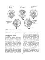
between their cardinalities. An example of inconsistency between cardinali-
ties is given in Figure 13.5. The cardinalities of the R1 relationship imply
that card(E1) ≥ 2 ∗ card(E2), and the cardinalities of the R2 relationship
imply that card(E2) ≥ card(E1). Except for the trivial solution, card(E1) =
card = (Ε2) = 0, that leads to a contradiction. In [8] and [9], an inequality
system is built with all the cardinalities. If the system has no solution, a con-
tradiction is detected.
The detection of inconsistencies can be completely automated. To
make the CASE tool attractive, it has to check that kind of consistency and
spot the contradiction. Consequently, a CASE tool that supports creative
design is not a static graphical editor but rather an intelligent system, able to
automatically enforce syntactic and semantic rules. These features contribute
to increasing designer productivity because they save checking time, and they
enhance the schema quality because the enforcement is more rigorously done
by the tool than by a human designer. Figure 13.6 gives the general architec-
ture of a creative design tool.
13.3.2.2 Reverse Engineering
Reverse engineering techniques have been proposed to reduce the increasing
cost of maintaining and modifying existing software [10]. The goal of reverse
engineering is to understand how software operates. This is done by
450 Advanced Database Technology and Design
E1
E2
R1
R2
1-1 2-3
1-n
1-1
Figure 13.5 An inconsistency due to a cardinality conflict.
identifying the different modules of the software and the interactions
between them in order to produce an abstract representation of the consid-
ered software. In the DB field, the reverse engineering process consists of
extracting the DB semantics from its implementation and abstracting the
semantics into the conceptual model. The process is based upon the analysis
of physical data structures and data instances. The reverse engineering of
DBs can be considered as conceptual modeling techniques to which CASE
support can be associated.
Three classes of reverse engineering approaches have been proposed
[11]: (a) reverse engineering of COBOL files, (b) reverse engineering of
navigational DBs, which include hierarchical and Codasyl DBs [12], and
(c) reverse engineering of relational and object DBs [11].
Compared to creative design, which starts from scratch, design by
reverse engineering starts from concrete structured components. The design
process is viewed as a transformation problem that maps a physical data
structure into an abstract schema. However, this mapping process is not triv-
ial, and it should be preceded by a discovering process of the entities and rela-
tionships between those entities. The discovering process is a kind of data
mining process that exploits knowledge sources such as the following:
•
File records, their internal structure with the embedded attributes,
types of attributes (particularly when they are multivalued or com-
plex attributes), the physical or logical pointers that relate different
records, primary and secondary keys, and so forth. The description
of file records is often embedded in data divisions of COBOL pro-
grams or in similar other languages.
•
DDL statements in the case of legacy DBs. These statements may be
Codasyl statements or SQL statements. In both cases, it is useful to
CASE Tools: Computer Support for Conceptual Modeling 451
Graphical
editor
Syntactic
checking
Repository
Designer
Figure 13.6 Creative design tool.
extract the logical structure underlying the definitions. From physi-
cal DB schemas, it is often possible to extract some integrity con-
straints such as unicity of values and functional dependencies.
•
DML statements, that is, DB queries written in a standard language
such as Codasyl or SQL. Database queries allow us to compute some
abstract objects from materialized objects. As is generally known, the
choice of objects to implement is done with respect to performance.
At the conceptual level, both abstract and materialized objects are
of the same importance with respect to their semantics. Then, the
former as well as the latter can be considered to be potential ele-
ments of the conceptual schema.
•
Data instances can also be exploited to abstract some structure, espe-
cially within legacy systems, either when source code is too large to
investigate or unavailable. Data mining techniques used for this pur-
pose are inspired by machine learning, knowledge discovering, and
statistics [13].
From this list, we can see how useful a CASE tool is in reverse engineer-
ing, especially in conceptual modeling by reverse engineering. Indeed, there
is no unified approach or common techniques or algorithms that exploit all
the knowledge referred to here. The only possible approach is to combine
several techniques into one common design environment and allow the
designer to apply the technique that best fits each situation. A general archi-
tecture for a reverse engineering CASE tool is portrayed in Figure 13.7.
452 Advanced Database Technology and Design
File
formats
DDL
statements
DML
statements
Data
instances
Mapping
process
Repository
Graphical
editor
Abstraction
process
Mining
process
Figure 13.7 Reverse engineering CASE tool.
13.3.2.3 Natural Language Understanding
Extracting data structure from natural language sentences is a difficult prob-
lem that may differ from natural language understanding or natural language
translation. Indeed, in a text written in natural language, only a part of
the global semantics is captured by DB models. Other aspects that deal with
processing and dynamics of the described information system are not cap-
tured in static data models. Extracting knowledge relevant to conceptual
modeling mainly consists in solving two problems: sorting relevant and
irrelevant assertions, and stating correspondences between natural language
concepts and conceptual modeling concepts.
Within the semantic part that can be captured by a conceptual data
model, one of the difficult problems is to decide whether a term in a given
sentence should be considered an attribute, object, relationship, or integrity
constraint. None of the classical techniques used in natural language process-
ing can solve that problem; only expert rules can produce relevant results.
At first glance, a sentence is turned into conceptual schema by abstract-
ing verbs into relationships, subjects and complements into participating
entities, and adverbs and adjectives into attributes. Some verbs are recog-
nized as well-known relationships; for example, the verb to be usually indi-
cates a generalization link, whereas the verb to have indicates a relationship
role or link between an entity (or a relationship) and its attribute.
Sentences can be interpreted as independent units, but they also appear
in the context of a global text. The interpretation of a given sentence can be
modified by the interpretation of other sentences. For example, from the sen-
tence, a product has a number, unit price, and supplier, we understand
that there is an entity named product characterized by three attributes:
number, unit price, and supplier. If we add a new sentence, such
as, Each product supplier, described by name and address, supplies 1 to
10 parts, we modify the previous interpretation by transforming the
attribute supplier into an entity described by two attributes (name and
address), and a relationship (supplies) that links it to product. The sec-
ond sentence introduces additional complexity related to the usage of syno-
nyms (product and parts) that have to be solved by the presence of a
dictionary.
Redundancy is a frequent problem in the textual specification. Some
new sentences, although true, do not augment the semantics of the applica-
tion, because the newly described facts can be deduced from the previous
ones. For example, in the following description, the third sentence is redun-
dant to the first two: A person has a name and age. An employee is a person.
CASE Tools: Computer Support for Conceptual Modeling 453
TEAMFLY
Team-Fly
®
An employee has a name and an age. Again, in the following example, there
is a redundancy, but it is an underhanded one: Employees and secretaries
are persons. A secretary is an employee. Indeed, the second sentence makes a
part of the first one redundantbecause a secretary is an employee, it is not
necessary to say that he or she is a person, as that fact can automatically be
deduced.
Conceptual modeling from a natural language interface involves many
aspects: natural language parsing, knowledge elicitation, and the sorting and
recovering of pertinent information with respect to the conceptual modeling.
Figure 13.8 shows a possible tool architecture for conceptual modeling from
natural language.
To reduce the complexity of natural language parsing, often only
restricted grammar is allowed, which leads to a technical jargon, easy to spec-
ify by the designer and easy to understand by the CASE tool. In the KASPER
project [14], a very restricted language called normalized language is
imposed, which uses standard grammar and standard terms. Both human
partners of different languages can use it as a specification language, and the
CASE tool can easily transform it into conceptual structures. However, some
experts may argue [15] that this simplicity provides only the appearance of a
natural language, and it is not the usual natural language dealing with the three
essential aspects of polysemy (homonymy, homotaxy), paraphrases (synon-
ymy, allotaxy, definition), and relation to the context (anaphora, implicit,
trope, spot). Some research projects of CASE tools such as DMG [16] and
NIBA [17] have extended their languages to quite complex sentences.
The interpretation of a natural language specification is not only a syn-
tactic process, but a very high level semantic process based on expert knowl-
edge from research in natural language processing and DB modeling.
454 Advanced Database Technology and Design
Domain
knowledge
Linguistic
knowledge
Electronic
dictionary
NL parser
Repository
Graphical
editor
Knowledge
elicitation
Concept
forming
Figure 13.8 Conceptual modeling from natural language.
13.3.3 Verification and Validation Tools
This section deals with the properties of a good conceptual schema and
shows how CASE tools support the verification of these properties. We can
divide the desired properties into three categories: (a) formal properties,
(b) quality factors, and (c) conformance with user needs. With respect to for-
mal properties, a good conceptual schema has to be consistent, complete, and
irredundant, if it is to give birth to a sound DB. With respect to quality, a
conceptual schema has to be understandable and able to evolve wherever the
analysis progresses. With respect to the user needs, a conceptual schema has
to conform to the requirements, that is, represent exactly what the user wants
to represent. The following subsections illustrate how CASE tools contribute
to the assessment of those desired properties and how far one can go in the
identification of those properties.
13.3.3.1 Formal Verification
As stated earlier, a good conceptual schema has to be intrinsically correct,
that is, consistent, complete, and irredundant. Depending on the conceptual
model used, these properties may vary from one model to another. Conse-
quently, the following desired list of properties is not exhaustive and applies
to the extended E/R model described in Figure 13.4.
Schema Consistency
Consistency is defined with respect to both the syntactic rules of the concep-
tual model and the semantic rules. A schema is syntactically consistent if it
satisfies the construction rules of the model. With respect to our conceptual
model, an instance of this model is syntactically consistent if it satisfies the
following properties:
•
The names of entities and relationships are distinct, that is, there is
unicity of names.
•
None of the attributes, entities, and relationships can exist inde-
pendently in the schema without characterizing or being related to
the others. This property is called nonisolation of concepts.
•
A relationship is at least a binary relationship between not necessar-
ily distinct entities.
•
A given relationship does not participate in another relationship.
CASE Tools: Computer Support for Conceptual Modeling 455