3D in Photoshop The Ultimate Guide for Creative Professionals PHẦN 2 docx
Bạn đang xem bản rút gọn của tài liệu. Xem và tải ngay bản đầy đủ của tài liệu tại đây (905.21 KB, 20 trang )
1.3.3. Depth of Field
In addition to the position and direction of the camera, Photoshop CS5 can
also simulate the aperture of the camera. This is done using the depth of field
settings. With these, you specify the part of your scene that is in focus and
that which is not e in much the same way you focus a lens on a subject when
taking a photograph (Figure 1.4a).
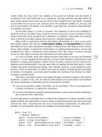
In Photoshop CS5, cameras have a pair of new parameters that allow an
artist to control depth of field. The Distance control determines the plane
in the scene where everything is in focus and the Blur control determines
how out of focus the areas behind and in front of the focus plane are
(Figure 1.4b).
FIG 1.4a Depth of Field set so that the front of the truck is in focus (the plane of focus) and everything else in front of or behind this plane is out of focus.
FIG 1.4b With the Camera Zoom Tool selected, you can set the distance of the focal plane and the amount of blur.
|
3D in Photoshop
6
1.4. Lights
Visual perception is our perception of how light interacts with matter.
Therefore lighting is a key component of a 3D scene, similar to the import-
ance of lighting in photography. Generally, light interaction with an object is
a very complicated process. Though the primary intent for 3D rendering is to
reproduce the light interaction with materials, steps are taken to simplify and
approximate these calculations. One such step is to limit the supported types
of light sources.
In Photoshop CS5, four types of light sources are supported. The first three
are standard lights that can be found, in one form or another, within any 3D
rendering package (point, infinite and spot lights).
1.4.1. Point Light
In some applications, this also may be known as an “omni” light. A point light
is a light source emitting light equally in all directions. You can think of this
like a candle or a light bulb. These types of lights have position, but do not
have a direction (Figure 1.5).
FIG 1.5 A point of light depicted by a spherical widget.
Scene
|
7
1.4.2. Infinite Light
In some applications, this also may be known as a “directional” light. An
infinite light is a light source emitting light parallel to a certain direction. This
is useful for simulating light sources that are very far away (e.g., sunlight).
These types of lights have direction, but do not have a defined position
(Figure 1.6).
1.4.3. Spot Light
Spot lights are similar to photographic spotlights or automobile headlights.
These lights have defined positions, direction, and a hotspot angle
(Figure 1.7).
FIG 1.6 An infinite light source depicted by the yellow widget with an arrow pointing in the direction of the light source.
|
3D in Photoshop
8
1.4.4. Image-Based Light
An image-based light in Photoshop CS5 provides an “environment” light
source, where the light source is not a point or a beam, but a texture map,
spherically wrapped around your scene (spherical panorama). One way to
imagine such a light is to think of it as a set of tiny point lights mounted on
the spherical cage all around your scene where every point light corresponds
to a single pixel in your texture map. In natural scenes, objects are rarely
illuminated by simple light sources only. For example, if we consider an
object within an empty room with a single lamp on the ceiling, while the
lamp provides most of the lighting (called “direct” lighting), some of the light
from the lamp gets reflected off the walls and back at the object (called
“indirect” lighting). Similarly, an object in an outside scene is illuminated not
only by the sun, but also by the sky and the ground. Thus, an image-based
light greatly facilitates modeling of real-world lighting environments. Instead
of approximating every light in your scene with a basic light source, you can
now just use an image-based light textured with a spherical panorama,
which is usually much easier to create (Figure 1.8).
1.5. Materials
Materials define the appearance of the object. These parameters include
diffuse (main color), specularity (highlights), transparency, reflectivity and
more. This derives from the notion that by setting all the properties in a given
way, one can create the impression that the rendered object is made of some
recognizable substance, like plastic, metal or glass. Materials often contain
textures (Figure 1.9).
FIG 1.7 A spot light depicted by the widget pointing in the direction of the light.
Scene
|
9
FIG 1.9 Sample materials found in Photoshop CS5 Materials Library presets.
FIG 1.8 Image-based light used to light this sphere. This light source is depicted by the spherical widget with
the image wrapped around it and handles that allow you to rotate the map and reposition the lighting.
|
3D in Photoshop
10
1.5.1. Photoshop-Supported Material Properties
Most Photoshop material pro perties have a base value (either a color or
a single value) and a m ap. I f a map is not specified, the base value is used
across the entire surface of the material. If a map is speci fied, the values in
the map override the base value. The alpha channel in the map is then
used to blend (multiply) the value at each pixel in the map against the
base value.
Diffuse
The diffuse color is the color that an object reflects when illuminated by
“good lighting,” that is, by direct daylight or artificial light that makes the
object easy to see (Figure 1.10). The color looks the same from all directions,
similar to matte paint (highlights and reflections both depend on the
direction from which you view the surface).
FIG 1.10 The image on the left is a diffuse map of a checkerboard pattern which is wrapped around a 3D sphere. Where each pixel on the left corresponds
to a position on the sphere.
Scene
|
11
Environment
Similar to the image-based light mentioned earlier, an environment map
specifies colors on a sphere that wrap around your entire scene. In the case of
the environment map, these colors are used for reflections (Figure 1.11).
Bump Maps
Bump mapping makes an object appear to have a bumpy or an irregular
surface (Figure 1.12). When you render an object with a bump-mapped
material, lighter (whiter) areas of the map appear to be raised (pulled
forward), and darker (blacker) areas appear to be pushed back.
Opacity Maps
You can select an image to make an object partially transparent. Lighter
(higher-value) values render as more opaque, darker areas render as more
transparent e exactly the same as the way Opacity works in the Photoshop
Layers panel (Figure 1.13).
Shininess/Glossiness Maps
Shininess and glossiness control specular highlights. Shininess is the
intensity or brightness of the highlights and glossiness is the size or spread
of the highlight. Therefore, shininess needs glossiness to be used as an
effect whereas glossiness does not need shininess (Figure 1.14). Using a map
for glossiness will alter where the highlights appear on your model. Using
a map for shininess will alter how bright the highlights appear on your
model.
FIG 1.11 This 3D model of a soda can has the background image set as its environment map with reflections on
(reflection value > 0).
Notes: If an environ-
ment map is not
specified for a
material, and an
image-based light is,
the color in the image-
based light will be
used for reflections by
default.
With reflections set to
0, you will not see the
effect of an environ-
ment map since it
won't have
anything e object or
surface e to bounce
off of.
|
3D in Photoshop
12
FIG 1.13 The right sphere shows the checkerboard texture
applied as an opacity map The color values in the texture
map shown in the upper left corner determines how
transparent that part of the object will be where black is
fully transparent.
FIG 1.14 Effects from different parameters of Glossiness and Shininess applied.
FIG 1.12 This sphere shows the left side without a bump
map and the right side with a bump map of this texture
applied. The bump map is the grayscale image on the
right where the color values determine if pixels are raised
or pushed back.
Scene
|
13
Self Maps
Self-illumination is added to the color computed from diffuse, highlight and
reflection shading. It can be thought of as luminous paint added to the total
color and is independent of lighting (Figure 1.15). Another way to think of
this effect is how lava is self-illuminated with the color red. You can use self-
illuminated materials on objects that represent lights to simulate things like
car headlights, and so on. White provides the most illumination, while black
blocks the illumination completely. It's often a good idea to design a self-
illumination map to match your diffuse map. For example, the diffuse map
might have small, yellow rectangles to represent windows, while the self-
illumination map consists of matching white rectangles against black to
illuminate the yellow windows.
Normal Maps
Normal Maps are textures used for simulating the lighting of bumps and
dents on a 3D object e the direction in which a surface faces. It allows the
program to add more detail to the 3D model without adding more polygons
and thus creating a larger model and file. It is especially useful for real-time
display devices such as game engines, and it can also be used in rendered
scenes and animations. Photoshop's normal maps are object space normal
maps. This means the RGB values in the texture are interpreted as a direction
in space (x, y and z, respectively).
Often, normal maps are used to improve the render quality of a model with
a low number of polygons (Figure 1.16). A game designer, for example, might
make a lowpolygon-count version of amodel that they have. They will then use
the high polygon-count version of the model to generate a normal map and
then apply that normal map to the low polygon-count version of the model.
FIG 1.15 Self-illumination can give lighting effects similar to this neon glow or the lighting you get from lava.
|
3D in Photoshop
14
Reflection/Refraction Maps
Reflection is how much light bounces off of an object. For example, chrome
is a highly reflective material and light in the scene will have a strong
reflection off the surface. Refraction defines how light behaves once it enters
an object e and therefore requires some amount of transparency to have any
effect (Figure 1.17). For example, looking through a ball made of glass has
a different effect than looking through a ball made of diamond.
Note: See Chapter 2 for more on refraction.
FIG 1.17 A transparent sphere will have different effects when looking through it based on what the refraction index (R.I.) is.
FIG 1.16 Normal map applied to a low poly-count model to improve render quality. The shape on the far left shows a high poly-count model. The second
image on the left shows the actual normal map. The third image on the left shows a low poly-count model without this normal map and the furthest
image on the right shows this same low poly-count model with normal map applied, resulting in an improved render quality.
Scene
|
15
1.6. UVs
UVs facilitate the placement of image texture maps on a 3D surface
(Figure 1.18). They exist to define a two-dimensional texture coordinate
system, called UV texture space. UVs are essential in that they provide the
connection between the surface of the mesh and how the image texture gets
mapped onto it. Basically, UVs act as marker points that control which points
(pixels) on the texture map correspond to which points (vertices) on the
mesh. Textures cannot be applied to surfaces that do not possess UV texture
coordinates. UV texture space uses the letters U and V to indicate the axes in
2D instead of x and y since x and y are used for the 3D positions of the
vertices.
In most cases, you map and arrange UVs after you have completed your
modeling and before you assign textures to the model. Otherwise, changing
the model will create a mismatch between the model and the UVs, and affect
how any textures appear on the model.
Understanding the concept of UVs and how to map them to a surface, and
subsequently lay them out accurately, is essential for producing textures on
surfaces when working in any 3D program. Understanding how UVs work is
also important when you want to paint on a 3D model. For example, if you
paint a stroke on a single face of a die, the paint may in fact replicate on each
respective face if the UV mapping dictates that the texture is tiled.
FIG 1.18 These two die have different UV maps applied to them. The UV map will determine how the numbers
(or image) are wrapped around the die.
|
3D in Photoshop
16
1.6.1. UV Maps
Adding 2D images to the surfaces of 3D objects provides a great way to
decorate them. This process is known as texture mapping. Imagine placing
a sticker onto a side of a bottle. The sticker represents the 2D image for
decorating the surf ace. The necess ary step is to determine where the sticker
should go. This is a “mapping” from some location on the sticker to some
place on the surface. Rather th an mapping sticker loca tions onto the
surface, it is more convenient to map locations on the surface onto loc ations
of the sticker. This allows the pattern of the sticker to be repeated if desired
across the surface of the bottle. This mapping from poi nts on the mesh
(e.g. bottle) into positions on the decal sticker (e.g. image) is known as a
“UV mapping”
Many models may come with an existing UV map. If not, Photoshop will
automatically UV map your models so that you can decorate them and paint
them from start. The way in which Photoshop maps your models is to divide
your object up into smaller pieces that can be squished flat. These flattened
pieces are then packed into different locations of your image. When you
paint or apply detail on that part of your 2D image, the colors show up on the
respective part of the 3D model.
This mapping from 2D image locations to locations on the 3D model can be
very confusing at first. Fortunately, in many cases you don't have to worry
much about the UV mapping. By painting directly in 3D onto the surface of
the model and Photoshop will automatically place any painted detail into the
right corresponding place in the 2D texture. It may be necessary to start with
a little painting in 3D before attempting to paint directly into the 2D image so
that you can get your bearings on which parts of the image map to which
parts of the surface.
The UV mapping process results in a correlation between the image and how
it appears as a texture when mapped onto the three-dimensional surface
mesh. UV mapping is a critical skill to master for accurate and realistic
textures on polygonal surfaces.
Photoshop CS5 Extended does not provide any tools for doing UV mapping.
Any models created from scratch in Photoshop will have UV coordinates
assigned and any models that are loaded from external sources that do not
have UV coordinates will have them assigned automatically if you wish to
have more control over how these UVs get assigned, there are third party
applications to allow you to do this.
Note: Although Photoshop CS5 Extended does not have any real control over
UV mapping, you can edit the properties of the material and offset and scale
the UV coordinates (Figure 1.19).
Scene
|
17
FIG 1.19 From the 3D Material panel, choose Edit Properties from the material fly-out and you can scale and offset the texture coordinates.
|
3D in Photoshop
18
Rendering: OpenGL (OGL)
and Adobe Ray Tracer (ART)
Rendering is the process of producing the pixels of an image from a higher-
level description of its components. Photoshop CS5 Extended supports two
different kinds of rendering e OpenGL and Ray Tracing. OpenGL rendering is
used for the Interactive (Painting) mode, which is very fast, but lacks
advanced rendering effects such as shadows, irradiance, inter-reflections,
anti-aliasing, high quality depth of field, and full HDR rendering. Even though
many modern high-end graphics cards are able to support some of those
advanced features, the intent to support a wide variety of mid and low-end
cards led to the decision that those features would only be supported by the
Ray Tracer. Thus, the OpenGL-supported effects are a subset of Ray Tracer-
supported effects, a trade-off for much faster rendering speeds necessary for
interaction and smooth 3D workflows (Figure 2.1 ).
2.1. OpenGL
OpenGL (Open Graphics Library) is a cross-platform graphics rendering API.
The main reason it is widely used is because many graphics cards or GPUs
CHAPTER 2
|
3D in Photoshop. DOI: 10.1016/B978-0-240-81377-6.10002-X
Copyright Ó 2010 Elsevier Inc. All rights reserved.
19
(Graphics Processing Units, used by graphics cards) support extremely effi-
cient hardware acceleration of OpenGL, which makes it an attractive solution
for interactive graphics rendering. The basic GPU architecture, however, only
allows for a certain set of rendering calculations, which results in a limited
number of visual effects.
Since the GPU mass-market introduction in the mid-1990s, the set of sup-
ported calculations has been gradually expanding and the GPU program-
ming interfaces have become more flexible. Because the driving force of
GPUs is video game acceleration, one can trace the history of GPU capabil-
ities by just looking at the effects you see in high-end video games over the
different years. Even though GPUs have come a long way since their
inception, their basic architectural limitations make certain rendering effects,
such as shadows and radiosity, hard to implement (i.e., slow and/or memory
intensive).
There are many 3D features that are dependent on the GPU in order to
function, it is required that you use a video card that has at least 512MB of
vRAM and supports OGL. 3D features that rely on OGL support are: Adobe
Repoussé, all overlays (progressive rendering tiling, 3D Axis, Lights, Meshes,
ground plane), Interactive/Painting rendering mode
*
, performance optimi-
zations (auto-hide layers and direct-to-screen) and Image Based Lights. To
check if OGL is enabled on your machine, navigate to Performance section in
your Preferences (Figure 2.2). If this option is disabled on your system, check
Photoshop system requirements and also be sure that the driver for your
video card is up to date. For further trouble-shooting, navigate to Help > GPU
in the Photoshop menu bar and/or check with your video card manufacturer.
FIG 2.1 The image on the left shows GL rendering and the image on the right shows Ray Tracer rendering (support for extra effects).
FIG 2.2 OGL-enablement checkbox
in the Performance section of
Photoshop Preferences.
*
There is a software fallback (Ray Tracer) for the Interactive (Painting) rendering mode
when OGL isn’t enabled but performance is significantly reduced.
|
3D in Photoshop
20
2.2. Ray Tracing
Ray tracing is a specific rendering approach in 3D computer graphics, which
uses a technique that follows rays from the camera outward. It produces
results similar to other techniques such as ray casting and scan line
rendering, but facilitates more advanced optical effects, such as reflection
and refraction, and is still efficient enough to be of practical use when high
quality output is desired.
Ray tracing is a technique which simulates the paths that light takes in the
real world as it starts from a light source, interacts with surfaces in the scene
and finally lands on the sensor of a camera. In the ray tracing algorithm, we
reverse these steps. For each pixel of our final image, we fire rays into the
scene. When those rays hit an object, the color is evaluated by the material
properties of the object at which point we fire more rays from the object to
the various light sources and to other objects. With ray tracing, it is
straightforward to faithfully reproduce such effects as hard and soft shadows,
color bleeding, reflection, refraction and depth of field. If one fires an inad-
equate number of rays for each pixel in the image, then the resulting image
will contain jagged edges (called aliasing) and will be quite noisy (Figure 2.3).
To overcome this noise (aliasing), dozens to hundreds of rays are fired for
each pixel. However, this can be very time-consuming e taking several
minutes to hours with a very large document. The Ray Tracer in Photoshop
CS5 uses a technique called progressive rendering, which continuously
renders the image with a small number of rays per pixel. Photoshop then
combines the results of the current pass with previous results to progres-
sively improve the rendered result. As such, the first few passes can contain
noticeable noise. However, showing this noisy image is intended to provide
the artist with a good idea of the lighting and where shadows will be cast.
FIG 2.3 The scene on the left is rendered with a low quality (draft) Ray Trace mode and on the right is rendered with a high quality (final) Ray Trace mode.
Rendering: OpenGL (OGL) and Adobe Ray Tracer (ART)
|
21
The progressive rendering can be interrupted at any time to make scene
changes. If it is accidentally interrupted, the rendering can be continued
without starting over by using the Resume Progressive Render command
found in the 3D menu as well as the 3D Panel fly-out.
Photoshop will also stop rendering portions of the image that it has detected
are sufficiently noise free. A portion of the image is considered done when
its noise gets below a given threshold. This threshold is controlled by a
Preference in the 3D preference pane (Figure 2.4).
2.2.1. Ray Tracing Effects
There are several effects which are either only present with ray tracing or
are much more accurate when using ray tracing. Shadows are only visible
when using ray tracing. All four of the light types are capable of casting
shadows, including soft shadows. In addition to casting shadows onto
objects in the scene, shadows can also be cast onto a ground plane and these
shadows can vary in terms of softness and opacity (Figure 2.5).
Image-based lighting gives an artist the ability to use an image to simulate
the lighting in a scene. 32-bit images are recommended for image-based
lights since at this bit depth you have over 4 billion levels to describe the
light, whereas with 8-bit images you are limited to only 256 levels of light
(0e255). If you have a broad range of light and dark areas, typically 256 levels
of light will not be enough.
With the Ray Tracer, you can also simulate effects such as reflection and
refraction. The reflection amount is controlled by the reflectivity material
FIG 2.4 High Quality Threshold
setting found in the Preferences for
3D settings.
FIG 2.5 Image on the left has a hard shadow casting on the ground plane compared to the image on the right with a soft shadow.
|
3D in Photoshop
22
parameter and the refraction amount is controlled by the opacity material
parameter. The extent to which light rays are refracted is determined by the
index of refraction. Water has an index of refraction of 1.33, glass 1.5 and
diamond 2.4. See Table 2.1 for more common refraction indexes.
TABLE 2.1 Refractive Index for common materials. You can find the setting for this in the
3D Materials Panel (at the bottom of the panel).
Rendering: OpenGL (OGL) and Adobe Ray Tracer (ART)
|
23
2.3. Other Render Settings
Ray Tracing and OGL are just two types of render modes. There are several
other render settings in Photoshop CS5. We have created presets of these
different types of settings that can be found in the 3D Scene Panel Render
Settings menu (Figure 2.6); two of the more interesting ones are Depth Maps
and Normal Maps.
2.3.1. Depth Map preset
Using the Depth Map render style, you can render an image where black
represents the farthest point in the scene and white represents the closest
point (Figure 2.7). The most effective way to use this render style is to
render in using a 32-bit image with a Levels adjustment (to specify
a narrow range of values). The adjustment layer is optional; however, it
gives you an easier way to see what is going on and edit the map. 32-bits
will give you a larger range of data to describe the depth, while with 8-bit
images, you only have 256 levels of depth. With this map you can
generate a smoother 3D object.
2.3.2. Normals preset
Photoshop CS5 also has a render style where the normals on the surface of
the object are visualized (Figure 2.8). This can be useful when you are looking
FIG 2.6 Render Settings presets found in the 3D Scene panel.
|
3D in Photoshop
24
for “bad” normals. Bad normals can result in paint not being applied properly
and incorrect renderings. (i.e. having holes in the paint applied). Normals that
are bad will stick out since Photoshop ends up depositing paint incorrectly in
a region of the mesh and you'll notice a color discontinuity. Usually the
normals over a smooth surface results in continuous colors of the map, hence
smooth transitions of colors on the object.
Note: For more information on normals see Chapter 1.
FIG 2.7 3D object of a dog with its depth map on the right. White values indicate that those pixels will be the
closest point and black values are the farthest.
FIG 2.8 3D object of a dog with its normal map on the right.
Rendering: OpenGL (OGL) and Adobe Ray Tracer (ART)
|
25