Designing and Implementing Linux Firewalls and QoS using netfilter, iproute2, NAT, and filter phần 9 pptx
Bạn đang xem bản rút gọn của tài liệu. Xem và tải ngay bản đầy đủ của tài liệu tại đây (1.4 MB, 29 trang )
Medium Networks Case Studies
[ 220 ]
tc class add dev eth0 parent 1:0 classid 1:10 htb rate 100Mbit
#upload to our network
tc class add dev eth0 parent 1:10 classid 1:100 htb rate 96Mbit
tc qdisc add dev eth0 parent 1:100 sfq quantum 1514b perturb 15
tc filter add dev eth0 protocol ip parent 1:0 prio 5 u32 match ip dst
1.2.3.0/24 flowid 1:100
#Upload to the internet from the tech department - 2Mbps
tc class add dev eth0 parent 1:10 classid 1:200 htb rate 2Mbit
tc qdisc add dev eth0 parent 1:200 sfq quantum 1514b perturb 15
tc filter add dev eth0 protocol ip parent 1:0 prio 5 u32 match ip src
1.2.3.16/29 flowid 1:200
#Upload to the internet from the other departments - 2Mbps
tc class add dev eth0 parent 1:10 classid 1:300 htb rate 2Mbit
tc qdisc add dev eth0 parent 1:300 sfq quantum 1514b perturb 15
tc filter add dev eth0 protocol ip parent 1:0 prio 5 handle 1 fw
flowid 1:300
For Eth2, we created the class 1:100 of 98Mbps and attached a tc lter to match our
nfmark 1, which matches all trafc from our network and the internal departments'
networks. The rest of the trafc going to 1.2.3.16/29 is internet trafc; so the 1:200
class of Eth2 has a 2Mbps limit.
The packets that go out of Eth1 are either from our class C 1.2.3.0/24 or from other
hosts on the Internet; so we created the 1:100 class of 98Mbps for trafc from our
network to the internal departments and the 1:200 class of 2Mbps for internet trafc.
The upload is limited on Eth0, for which we created the 96Mbps class 1:100 with a
lter to match all packets going to hosts in our network. If packets going out of Eth0
are not destined to 1.2.3.0/24, then they will not match the 1:100 class, and if they are
from 1.2.3.16/29, they will match the 1:200 class of 2Mbps, and it means that this is
upload trafc from the technical department to the Internet.
Trafc going out of Eth0 that is marked with nfmark 1 is from the NATed internal
departments and is matched on the 1:300 class of 2Mbps.
QoS on the Core Router
The core router has four interfaces:
eth0, connected to the upstream provider
eth1, connected to the servers LAN
eth2, connected with the intranet server
eth3, connected to the customers
•
•
•
•
Chapter 7
[ 221 ]
We will not perform trafc shaping on eth1 (servers) and on eth2, because we want
as much bandwidth as we can get for the servers, and the internal departments are
limited locally on the intranet server.
The interfaces that will have HTB qdiscs will be eth0 for upload and eth3 to shape
the customers' download.
We will start with eth3, which will have a 16kbit default class. First, we will
create a 100Mbps class for the access server IP address, the wireless server, and
192.168.100.0/24, which is used for switches and access points' management IP
addresses. For the dial-up customers, we will allocate 1Mbps of bandwidth.
We'll create a 2Mbps class in which we will add customers who buy our service with
CIR/MIR 256kbps/2Mbps. If the number of customers who buy this service grows,
we can always increase the limit of this class, which is the parent class for each
customer's class.
For the upload interface, the classes will look about the same, except that in the rst
100Mbps class, we will add the IP addresses of the servers and the subnets for which
we perform shaping on the wireless and intranet servers.
The script looks like this:
#!/bin/bash
#download speed first - on eth3
#delete root qdisc (this will destroy all classes)
tc qdisc del dev eth3 root
#attach root qdisc and create the 100Mbps root class
tc qdisc add dev eth3 root handle 1: htb default 9999
tc class add dev eth3 parent 1:0 classid 1:10 htb rate 100Mbit
#access server and wireless server
tc class add dev eth3 parent 1:10 classid 1:100 htb rate 100Mbit
tc qdisc add dev eth3 parent 1:100 sfq quantum 1514b perturb 15
tc filter add dev eth3 protocol ip parent 1:0 prio 5 u32 match ip dst
1.2.3.130 flowid 1:100
tc filter add dev eth3 protocol ip parent 1:0 prio 5 u32 match ip dst
1.2.3.131 flowid 1:100
tc filter add dev eth3 protocol ip parent 1:0 prio 5 u32 match ip dst
192.168.100.0/24 flowid 1:100
#dialup users
tc class add dev eth3 parent 1:10 classid 1:200 htb rate 1Mbit
Medium Networks Case Studies
[ 222 ]
tc qdisc add dev eth3 parent 1:200 sfq quantum 1514b perturb 15
tc filter add dev eth3 protocol ip parent 1:0 prio 5 u32 match ip dst
1.2.3.64/26 flowid 1:200
#1st Customer with CIR=MIR - 1.2.3.133
tc class add dev eth3 parent 1:10 classid 1:300 htb rate 1Mbit
tc qdisc add dev eth3 parent 1:300 sfq quantum 1514b perturb 15
tc filter add dev eth3 protocol ip parent 1:0 prio 5 u32 match ip dst
1.2.3.133 flowid 1:300
#2Mbps class for CIR=256, MIR=2Mbps service
tc class add dev eth3 parent 1:10 classid 1:1000 htb rate 2Mbit
#1st client for the CIR=256, MIR=2Mbps service - 1.2.3.134
tc class add dev eth3 parent 1:10 classid 1:1001 htb rate 256Kbit ceil
2Mbit
tc qdisc add dev eth3 parent 1:1001 sfq quantum 1514b perturb 15
tc filter add dev eth3 protocol ip parent 1:0 prio 5 u32 match ip dst
1.2.3.134 flowid 1:1001
#default class
tc class add dev eth3 parent 1:10 classid 1:9999 htb rate 16Kbit
#Upload speed - on eth0
#delete root qdisc (this will destroy all classes)
tc qdisc del dev eth0 root
#attach root qdisc and create the 100Mbps root class
tc qdisc add dev eth0 root handle 1: htb default 9999
tc class add dev eth0 parent 1:0 classid 1:10 htb rate 100Mbit
#access server and wireless server
tc class add dev eth0 parent 1:10 classid 1:100 htb rate 100Mbit
tc qdisc add dev eth0 parent 1:100 sfq quantum 1514b perturb 15
tc filter add dev eth0 protocol ip parent 1:0 prio 5 u32 match ip src
1.2.3.130 flowid 1:100
tc filter add dev eth0 protocol ip parent 1:0 prio 5 u32 match ip src
1.2.3.131 flowid 1:100
tc filter add dev eth0 protocol ip parent 1:0 prio 5 u32 match ip src
1.2.3.0/29 flowid 1:100
tc filter add dev eth0 protocol ip parent 1:0 prio 5 u32 match ip src
1.2.3.8/30 flowid 1:100
tc filter add dev eth0 protocol ip parent 1:0 prio 5 u32 match ip src
1.2.3.16/29 flowid 1:100
tc filter add dev eth0 protocol ip parent 1:0 prio 5 u32 match ip src
Chapter 7
[ 223 ]
1.2.3.32/27 flowid 1:100
#dialup users
tc class add dev eth0 parent 1:10 classid 1:200 htb rate 1Mbit
tc qdisc add dev eth0 parent 1:200 sfq quantum 1514b perturb 15
tc filter add dev eth0 protocol ip parent 1:0 prio 5 u32 match ip src
1.2.3.64/26 flowid 1:200
#1st Customer with CIR=MIR - 1.2.3.133
tc class add dev eth0 parent 1:10 classid 1:300 htb rate 1Mbit
tc qdisc add dev eth0 parent 1:300 sfq quantum 1514b perturb 15
tc filter add dev eth0 protocol ip parent 1:0 prio 5 u32 match ip src
1.2.3.133 flowid 1:300
#2Mbps class for CIR=256, MIR=2Mbps service
tc class add dev eth0 parent 1:10 classid 1:1000 htb rate 2Mbit
#1st client for the CIR=256, MIR=2Mbps service - 1.2.3.134
tc class add dev eth0 parent 1:10 classid 1:1001 htb rate 256Kbit ceil
2Mbit
tc qdisc add dev eth0 parent 1:1001 sfq quantum 1514b perturb 15
tc filter add dev eth0 protocol ip parent 1:0 prio 5 u32 match ip src
1.2.3.134 flowid 1:1001
#default class
tc class add dev eth0 parent 1:10 classid 1:9999 htb rate 16Kbit
It looks like we didn't miss anything; so we should be happy with this conguration.
After applying this script, everything runs OK, but after a while we see some
service interruptions on our upstream provider link. The upstream provider tells
us everything is OK on its side, but the packet loss is very high between us, and
after about 20-30 seconds, the provider can't see our MAC address for another 20-30
seconds, and this cycle repeats itself forever.
Since we haven't modied anything for a long time and this has just started
happening, we might think it's a hardware problem. Well, it isn't. Since packet loss
might come from a faulty cable or NIC, the strange part is that they don't see our
MAC address for a while. Looking at the default class on eth0, we see that it's full,
and so, someone in our network might have changed their IP address, but that
shouldn't affect us.
Medium Networks Case Studies
[ 224 ]
If we take a closer look at the QoS script, we see that we don't nd the IP address
assigned by the provider—1.1.1.1. After 20-30 seconds, the ARP cache of the provider
for our IP address expires, and so, its router sends a request to our IP address
(1.1.1.1) and asks for our MAC address. Since we didn't add 1.1.1.1 anywhere in the
QoS script, the reply from our router to that requests has to wait inline on the
default class.
So, the solution to this problem is to add the IP address 1.1.1.1 in the lters for the
100Mbps class 1:100 of the eth0 interface.
The reason we left this out on purpose is that we have seen
a lot of network administrators doing that and taking a lot
of time to troubleshoot this problem.
Summary
We saw in this chapter some pretty complicated networks. We also saw that building
rewalls and QoS for such networks is not so complicated. However, it is very
important to draw the network and identify security breakpoints to be able to create
a rewall that will protect your network.
In my opinion, the most important things about security are knowing your network,
building it in an intelligent manner and with security in mind, and most of all,
understanding how packets ow in your network.
Understanding the ow of the packets in the network is essential for people who
want to build good rewalls and intelligent QoS. I've seen simpler networks than
the ones presented here with very complicated rewalls, which had rules that didn't
belong there or that could be reduced to much simpler ones.
I've also seen some networks that were badly thought out from the beginning. For
instance, think about the second example of this chapter and how it would be if we
place one server on the customer interface, some customers in the server farm switch,
etc. This would complicate our rewalls a lot. Also, a badly thought out subneting
of the network would mean generating kilometers of rewall rules and a lot of
tc lters.
It may happen at some point that you have to administer a network badly subneted
and badly thought out by others. To be honest, taking each part of it and building
security is way more difcult and time consuming than redrawing the network,
renumbering IP address, and rebuilding the rewalls. Of course, all of these operations
must be done always thinking about minimal downtime for servers and customers.
Large Networks Case Studies
There are different points of view in designing and deploying large networks using
Linux routers or dedicated routers that can handle very high data rates.
While some prefer to pay a large amount of money for dedicated routers for
which they have technical support and well-dened technical characteristics
and limitations, others want to reduce the costs by building such networks using
powerful computers running Linux, offering a much larger exibility in deployment.
This is not an easy choice at all. The business point of view has ups and downs when
considering the two options. The biggest advantage of using dedicated routers from
the business point of view is that the value of the network rises considerably if the
network is built to be sold. What I mean is that if you build a large network using
Cisco routers, you have more chance of selling it to a bigger provider than if you've
build the network with Linux routers.
Using dedicated routers you will have the following advantages:
Wide range of network interfaces (ATM, SDH/SONET, Ge, Fe, etc.)
Less likely software bugs, and technical support from producers
Well-known and well-dened technical limitations
Standard protocol implementations
High market value of the network
and the following disadvantages:
High costs for implementation, upgrade, and personnel training
Less application exibility
Using Linux routers has its advantages and disadvantages also. From the
advantages, we can mention:
•
•
•
•
•
•
•
Large Networks Case Studies
[ 226 ]
Low deployment costs and low costs for upgrades
Personnel cost less, and are easier to nd
High application exibility—large open source repository that can
be implemented
and from the disadvantages, we can mention:
Low value on the market if the network is sold
A smaller range of network interfaces available
Higher probability of software bugs
Experienced network administrators usually prefer using dedicated routers because
of well-known technical limitations and protocol standardizations. However, from
my experience, the best way of implementing large networks is as a combination
between those two; however, we prefer using Linux as much as we can because of
the lower costs and higher application exibility.
The biggest disadvantage in using Linux is that there are fewer options about the
network interfaces that can be used in a Linux router. To give a simple example, we
had to decide on using a router for the following application:
The router we had to choose had three uplink connections to other backbones of
our network in a geographically distanced place. We rented an STM-1 connection
from a carrier, an E3 connection from another carrier, and a FastEthernet connection
from a third carrier. The router had to have three Gigabit connections to three
distribution networks.
As you can probably guess, there is a large amount of trafc passing through this
router. Because of the variety of interfaces, our rst thought was to buy a high-capacity
router with one E3, one STM-1, one FastEthernet, and three Gigabit interfaces that
•
•
•
•
•
•
Chapter 8
[ 227 ]
can handle a high number of packets per second; so the rst choice would be to buy
a router equivalent to (or an actual) a Cisco 7206 VXR with NPE (Network Processor
Engine) running at at least 300 Mhz.
This raises the problem that we have to have other equivalent routers in the
backbones with the STM-1 and E3 connections. Such a router costs at least $30,000,
and adding the extra costs for the backbone routers, we would have deployment
costs of over $50,000. More than that, we can think about value-added services such
as dynamically allocating bandwidth for customers in the access networks, which
would require dedicated machines.
There are some network hardware manufacturers that offer media converters for
applications in which you need E3/T3 over SoNet or STM-1 over SoNet. These
media converters have one E3/T3 or STM-1 interface, and one FastEthernet or
Gigabit Ethernet; so we decided to see how they handle large trafc.
We bought a 3 GHz dual-Xeon Intel server with 2 Gigabit Ethernet onboard and a
NIC with 4 Gigabit Ethernet for about $3,500, a pair of E3-to-FastEthernet converters,
and a pair of STM-1 to Gigabit Ethernet converters, all of them for less $10,000.
We installed Linux on the server and discovered that it could very well handle the
amount of trafc we needed.
At the exact moment this chapter was written, it was forwarding a total of:
total: 299.61 Mb/s In 293.28 Mb/s Out - 80742.2 p/s In 78790.2
p/s Out
on all interfaces with a load average: 0.95, 0.94, 0.72. It also has a total of 2700 HTB
classes and 3,000 lters for those classes.
The optimum way of building large networks in my opinion
is to choose Linux as often as you can. There are some
applications in which you can't use Linux, and so I think is
better to reserve the budget for buying high-cost routers for
those applications and try to use Linux in the applications in
which you can.
Large Networks Case Studies
[ 228 ]
Thinking Large, Thinking Layered Models
At the risk of sounding repetative, I will state the fact that the key of building a good
and secure rewall is to design the network in an intelligent way, identify points of
security, and understand how packets are owing through the network.
When designing and deploying large networks, it's recommended to identify how
and where routers must be placed in the network and how to scale the routers for the
functions they must perform.
Large networks are often built in layers. The largest networks use a three-layered
hierarchy consisting of the following three layers:
Core layer
Distribution layer
Access layer
The three-layer network hierarchy is not always suited for all large networks, and
some routers can perform functions of more than one layer.
Usually, a three-layered network design looks something like this:
•
•
•
Chapter 8
[ 229 ]
The core layer usually contains routers that have internet or local peering
connections. There are high-speed links between them, and routes are distributed
between them for better load balancing of internet and peering connections.
The distribution layer contains routers that route several customers in different
locations, while the access layer contains routers at the customer premises, which can
even be SOHO routers for smaller customers.
Of course you can have customers connected directly to a core router, which means
that the core router also performs distribution and access layer functions. This is not
a bad thing if the customer is a large one, because you might want to distribute them
a large routing table without passing it through a distribution router, but usually it's
better to pass customers through distribution routers where you do QoS so that the
core routers are not overloaded with QoS functions.
A Real Large Network Example
The network we are going to present here is actually working in real life. Of course,
we will replace the real IP addresses of the routers and servers.
The network is deployed at a large provider of Internet and IP telephony services.
The point is to understand how packets ow through the network, to identify the
security breakpoints, and build proper rewalls for the network.
We will present here only the important parts of the network as it is.
Let's start by looking at the network architecture and explain how the network is
built and what's in the network.
Large Networks Case Studies
[ 230 ]
A Brief Network Overview
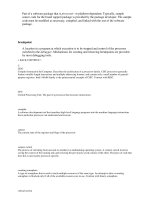
The core of the network is represented in the following gure:
Core-1 is a router that has one FastEthernet connection to an ISP from which we
buy 34Mbps of internet services. It is located in the main datacenter of this company
and has a ber optic connection at 100Mbps to Core-2 located in another datacenter.
Core-1 also has a ber optic connection at 1000Mbps (1Gbps) to Core-3.
Core-2 has one internet connection of 34Mbps connected to Provider2. Provider2 also
has a large national network; so we have a peering connection with it on a 100Mbps
interface. Core-2 is connected to Core-1 via a 100Mbps link.
Core-3 has a backup internet connection of 10 Mbps. It is also connected to a local
exchange network for local peerings on a 100Mbps interface and to another provider
(Provider4) on another 100Mbps interface. The connection with Provider4 is only
for peering.
Chapter 8
[ 231 ]
Core-4 is physically located in City-2, which is a considerable geographical distance
away from City-1. It has an STM-1 connection to Core-3 (Gigabit interface using
STM-1 to GE converter), one FastEthernet connection to a provider that offers us a
service of MPLS VPN (34 Mbps), and another FastEthernet to a provider offering an
Ethernet Over MPLS connection (34 Mbps). The City-3 router is connected through
Core-4 using an E3 to FastEthernet converter.
All core routers are Linux machines and run Zebra, which is a routing software
package distributed under GNU General Public License for BGP connections. Zebra
can be found at .
City-1
Datacenter-1 is the place for most voice interconnections for this provider; so it's the
most important voice node in the network.
The City-1 part of this ISP network has the following particularities:
It holds most of the voice equipment of the network.
Customers of Internet services are only broadband customers with large
bandwidth needs.
It holds most of the web hosting and database servers (the server farm).
Datacenter-1 is located in a building where there's an ofce with tech, sales,
marketing, and commercial people, but it's not the Headquarters of the ISP.
•
•
•
•
Large Networks Case Studies
[ 232 ]
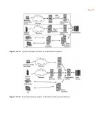
The network looks like this:
Core-1 has one interface connected to the core switch of Datacenter-1. The voice
equipment has special designated racks, and it has its own switch and their
own VLAN.
Another VLAN is created on the core switch for the server farm, which has web,
email, and database servers.
The Distribution-1 router is a Linux machine with three FastEthernet cards: one
connected to the core switch, one connected to a LAN switch for the ofce, and one
to a distribution switch from which the distribution network begins.
City-2
Datacenter-4 is located in City-2 in the same building as the ISP Headquarters.
The City-2 part of the network has the following particularities:
It has a very large and complex self-owned ber optics network.
It has one high-density DSLAM operating ADSL2+ (192 ports).
It has a large and complex wireless network.
•
•
•
Chapter 8
[ 233 ]
It has a wireless link that connects a smaller nearby city (City-5).
Datacenter-4 hosts voice equipment for local interconnections.
Datacenter-4 hosts a server farm for web, mail, database, and intranet servers.
The City-2 network has over 2000 home-users and over 100 broadband
customers.
Over 30% of the clients are subscribed to the IP telephony network of this ISP.
The network looks like this:
Core-4 is a Linux router that handles a lot of network trafc. It has six network
interfaces, three of them connected to the other core routers, two connected to a core
switch in Datacenter-4, and one to the ber optics switch also located in Datacenter-4.
Into the core switch of Datacenter-4 are connected some voice equipment, a server
farm, and an ADSL2+ DSLAM. The server farm and the voice equipment are in
the same VLAN as one of Core-4's NICs, and the DSLAM is in a VLAN with the
second NIC of Core-4 connected to the core switch. ADSL clients have modems that
function in bridge mode; so it shouldn't be in the same VLAN with the servers or
•
•
•
•
•
Large Networks Case Studies
[ 234 ]
voice equipment. For the same reason, we didn't place the DSLAM in the FO switch,
because high broadcast data rates may affect the performance of ADSL clients with
poor lines.
The ber optic network covers the entire city and has a ring topology at Layer 2.
Some corporate clients are connected directly to the FO network, meaning they
use Core-4 as the default gateway. Throughout the network, distribution routers
annotated in the gure with DR-1…DR-8 are placed in distribution points to route
subnets used for home users and companies connected to the distribution network.
In some of the distribution points, there are a few wireless access points used to
connect wireless customers.
In the same VLAN with the DSLAM, there's an E3 to FastEthernet converter that
connects City-3 and City-4.
City-3 and City-4
City-3 is located at about 40 km from City-2 and City-4 is located at 20km from
City-3 (60km from City-2).
They are smaller cities and both have ber optics distribution networks. City-3 has
a wireless distribution network and a Cisco AS5350 for voice interconnection with
local telcos.
Chapter 8
[ 235 ]
The network looks like this:
The Core Network Conguration
As we did in the earlier chapters of the book when we explained other rewall
scenarios, we will present how the network conguration is built to fully understand
how packets travel in the network. Without a good understanding of this process,
good rewall and QoS congurations are practically impossible to achieve.
We will build the network conguration rst on the core and distribution levels, and
only afterwards will we build rewalls and QoS .
All routers in the core level run the BGP routing protocol (Border Gateway Protocol)
described in RFC1771. With Linux, BGP is very well implemented using the Zebra
router project found at .
Zebra has support for other routing protocols and has a modular architecture having
a daemon for each routing protocol it supports. The Zebra daemon is used to talk
to the kernel in the way of adding and removing routes received from its routing
daemons. Each daemon (protocol) has a status port that can be used for conguration
and troubleshooting with commands very similar to Cisco IOS.
Large Networks Case Studies
[ 236 ]
BGP version 4 (BGP-4) described in RFC1771 is the routing protocol used between
ISPs to exchange routing information, so we can denitely say that BGP-4 is the
routing protocol that gets the Internet to work. BGP is a very complex protocol
and we can't cover even a short introduction in a few pages; so if you are not
familiar with BGP, we suggest reading an introduction from Cisco at
For obvious security reasons, we replaced the IP addresses in the real situations and
the AS numbers with private AS numbers. The private AS number block is from
AS64512 to AS65534.
Our AS number is AS65000, as presented in the gure. The IP addresses we have are:
1.1.1.0/24, which we use for our routers
1.1.10.0/24, which we use for the voice equipment
1.1.48.0/20 and 1.1.96.0/20, which we use in City-2 to provide
internet services
1.1.168.0/22, which we use in City-1 to provide internet services
•
•
•
•
Chapter 8
[ 237 ]
1.1.48.0/20 and 1.1.96.0/20 being used in City-2 will be advertised by the
Core-4 router, and 1.1.160.0/22 will be advertised by Core-1. Since most of the voice
equipment is in City-1, the network 1.1.10.0/24 will be advertised by Core-1, and a
subnet of 1.1.10.0/27 by Core-4.
1.1.1.0/24 can be advertised by any routers, but we will use Core-1 for the job
because it's one of the routers with the most core links (three, same as Core-4) and it's
a border router and closest to the other border routers.
To load-balance the links, we will use AS-path prepends for the external links and
metrics for the core links.
Core-2
Core-2 has four BGP connections: two iBGP (internal BGP) and two eBGP (external
BGP). We will use the internet connection to Provider-2 as the main connection for
1.1.48.0/20, which has more trafc than 1.1.96.0/20, and we will use prepends for
1.1.96.0/20 and 1.1.168.0/22.
The BGP conguration is like this:
core-2-bgpd# sh run
Current configuration:
!
hostname core-2-bgpd
password password
enable password enable
log file /var/log/bgpd.log
service advanced-vty
!
router bgp 65000
neighbor 1.1.1.190 remote-as 65000
neighbor 1.1.1.22 remote-as 65000
neighbor 1.3.1.89 remote-as 65002
neighbor 1.3.2.1 remote-as 65002
!
address-family ipv4
!
neighbor 1.1.1.190 activate
neighbor 1.1.1.190 route-reflector-client
neighbor 1.1.1.190 default-originate
neighbor 1.1.1.190 route-map core-1-in in
neighbor 1.1.1.190 route-map core-1-out out
!
Large Networks Case Studies
[ 238 ]
neighbor 1.1.1.22 activate
neighbor 1.1.1.22 route-reflector-client
neighbor 1.1.1.22 default-originate
neighbor 1.1.1.22 route-map core-4-in in
neighbor 1.1.1.22 route-map core-4-out out
!
neighbor 1.3.1.89 activate
neighbor 1.3.1.89 next-hop-self
neighbor 1.3.1.89 route-map provider-2-inet-in in
neighbor 1.3.1.89 route-map provider-2-inet-out out
!
neighbor 1.3.2.1 activate
neighbor 1.3.2.1 next-hop-self
neighbor 1.3.2.1 route-map provider-2-peering-in in
neighbor 1.3.2.1 route-map provider-2-peering-out out
!
network 1.1.48.1/32
!
exit-address-family
!
access-list prefer-provider-2 permit 1.1.48.0/20 exact-match
access-list prefer-provider-2 permit 1.1.10.0/24 exact-match
access-list prefer-provider-2 permit 1.1.1.0/24 exact-match
!
access-list prepend-provider-2 permit 1.1.96.0/20 exact-match
access-list prepend-provider-2 permit 1.1.168.0/22 exact-match
!
access-list flood permit 1.1.48.1/32 exact-match
!
access-list defaultgw permit 0.0.0.0/0 exact-match
!
access-list permitany permit any
access-list denyany deny any
!
route-map core-1-in permit 9
match ip address prepend-provider-2
set metric +2
!
route-map core-1-in permit 10
match ip address prefere-provider-2
set metric +1
!
route-map core-1-out permit 10
match ip address permitany
Chapter 8
[ 239 ]
!
route-map core-4-in permit 9
match ip address prepend-provider-2
set metric +1
!
route-map core-4-in permit 10
match ip address prefere-provider-2
set metric +4
!
route-map core-4-out permit 10
match ip address permitany
!
route-map provider-2-inet-in permit 10
match ip address defaultgw
!
route-map provider-2-inet-in deny 11
match ip address denyany
!
route-map provider-2-inet-out permit 9
match ip address flood
set community 65002:6666
!
route-map provider-2-inet-out permit 10
match ip address prefere-provider-2
!
route-map provider-2-inet-out permit 11
match ip address prepend-provider-2
set as-path prepend 65000 65000
!
route-map provider-2-inet-out deny 12
match ip address denyany
!
route-map provider-2-peering-out permit 10
match ip address prefere-provider-2
!
route-map provider-2-peering-out permit 11
match ip address prepend-provider-2
!
route-map provider-2-peering-out deny 12
match ip address denyany
!
route-map provider-2-peering-in deny 10
match ip address defaultgw
!
Large Networks Case Studies
[ 240 ]
route-map provider-2-peering-in permit 11
match ip address permitany
!
line vty
!
end
This is a simple BGP conguration for Core-2 that has four BGP peers each with a
route map for input and route map for output.
Core-2 originates the default route to Core-1 and Core-4. It receives the default route
from the external peer 1.3.1.89, but it shouldn't receive the default route from 1.3.2.1,
which is a peering BGP connection.
The conguration has an example on how to lter an IP address (1.1.48.1) on an
upstream link. The upstream provider Provider-2 has the community 6666 for
ltering IP addresses. In case of a ood attack to one of our IP addresses (in this
case 1.1.48.1), we advertise the IP address to the provider setting the community to
65002:6666 so they lter the IP address without affecting our 34Mbps connection.
Routes to our networks are received by Core-2 from Core-1 and Core-4. We will set
metric +1 for the routes found in ACL prefer-provider-2 for the Core-1 iBGP and
metric +4 for the Core-4 iBGP. Since the route with the lowest metric is preferred,
Core-2 will prefer Core-1 for the networks in the prefer-provider-2 ACL.
We also mangled metrics for the networks in the ACL prepend-provider-2 to have
the lowest metric for those routes on the EoMPLS connection with Core-4. However,
metrics sum together and we have to set a metric of minimum +1 for the network
1.1.168.0/22 somewhere from Core-1 to Core-2 through Core-4 because that network
must be preferred to the direct link between Core-2 and Core-1.
Core-1, Core-3, and Core-4
We picked Core-2 rst to show the conguration because it has the simplest
conguration. However, starting from the BGP conguration for Core-2 we can build
the other core routers congurations.
Core-3 has two peering eBGP peers, one internet eBGP peer used for backup, and
two iBGP peers (Core-1 and Core-4).
Since the core link from Core-3 to Core-4 has the largest bandwidth of all core links
to Core-4, this link normally carries most of the trafc to Core-4; so we should play
with metrics to route most of the trafc to Core-4 on this link. Other BGP attributes
can also be used (local preference, prepends, weights, or communities) but we prefer
using metric for this job.
Chapter 8
[ 241 ]
Core-3 has the particularity that the internet connection to Provider3 is for backup
only; so what we should do is to create an access list that contains all of our
networks, and use prepends in the route map, as follows:
access-list ournetworks permit 1.1.48.0/20 exact-match
access-list ournetworks permit 1.1.10.0/24 exact-match
access-list ournetworks permit 1.1.1.0/24 exact-match
access-list ournetworks permit 1.1.96.0/20 exact-match
access-list ournetworks permit 1.1.168.0/22 exact-match
!
route-map provider-3-out permit 10
match ip address ournetworks
set as-path prepend 65000 65000 65000
Core-1 and Core-4 have a few particularities more because the core link between
them is MPLS VPN. If all the other core links are Layer 2 connections, MPLS VPN is
a Layer 3 connection, meaning that there some routers between Core-1 and Core-4
that don't belong to us.
You can see in the gure that the IP addresses are 10.10.2.2/30 on the Core-1
interface to Core-4 and 10.10.2.6/30 on the Core-4 interface to Core-1. Those IP
addresses are private IP addresses, and they are not in the same subnet. So, what we
need to do is to make BGP connections to the routers 10.10.2.1 and 10.10.2.5, which
belong to Provider-1 (from which we acquired the MPLS VPN service) from Core-1
and Core-4, and a multi-hop BGP connection between Core-1 and Core-4.
On Core-1, we will place a static route to Core-4 through 10.10.2.1:
route add 10.10.2.6 gw 10.10.2.1
and congure the two BGP peers as follows:
router bgp 65000
neighbor 10.10.2.1 remote-as 65001
neighbor 10.10.2.6 remote-as 65000
!
address-family ipv4
!
neighbor 10.10.2.1 next-hop-self
neighbor 10.10.2.1 allow-as-in 1
neighbor 10.10.2.1 route-map core-4-in in
neighbor 10.10.2.1 route-map core-4-out out
!
neighbor 10.10.2.6 disable-connected-check
neighbor 10.10.2.6 route-map core-4-in in
Large Networks Case Studies
[ 242 ]
neighbor 10.10.2.6 route-map core-4-out out
!
!
route-map core-4-in permit 10
set ip next-hop 10.10.2.1
!
On Core-4, we will set a static route to 10.10.2.2 through 10.10.2.5 and build a
similar conguration.
This summarized example conguration is taken from an
existing network conguration. Building the entire BGP
congurations for all routers is beyond the scope of this
book. However, we hope this example gives you a starting
point for your BGP congurations.
Security Threats
So far, we have built the core network conguration. Now, for all core routers we
need to secure SSH, BGPd, Zebra, and SNMP (in such networks, SNMP is a must
because we need to create graphs for trafc, load average, and so on).
Core Routers INPUT Firewalls
The INPUT policy of the core routers should be DROP. We should accept SSH, SNMP,
Zebra, and BGPd status from the network administrators, DNS packets from our
DNS servers, ICMP packets, packets on the loopback interface, and TCP packets to
port 179 from our BGP peers.
The following example script is designated for all core routers. What needs to be
changed is the IP addresses of the BGP peers. This example is for the Core-2 router:
#!/bin/bash
I=/sbin/iptables
#INPUT policy ACCEPT and at the end DROP
$I -P INPUT ACCEPT
#Flush and zero chains
$I -F
$I -X
Chapter 8
[ 243 ]
$I -N manag
#Lo + dns + icmp + !syn
$I -A INPUT -i lo -j ACCEPT
$I -A INPUT -p tcp ! syn -j ACCEPT
$I -A INPUT -p icmp -j ACCEPT
$I -A INPUT -p UDP sport 53 -s our.dns.server.ourcompany.
org -j ACCEPT
$I -A INPUT -p UDP sport 53 -s our.dns.server2.ourcompany.
org -j ACCEPT
#Management chain - ssh, snmp, zebra, BGPD
$I -A INPUT -p TCP dport 22 -j manag #ssh
$I -A INPUT -p UDP dport 161 -j manag #snmp
$I -A INPUT -p TCP dport 2601 -j manag #zebra
$I -A INPUT -p TCP dport 2605 -j manag #bgpd
#Network Administrators IP addresses
$I -A manag -s 1.1.40.0/27 -j ACCEPT
$I -A manag -s 1.1.169.0/27 -j ACCEPT
$I -A manag -j DROP
#Our BGP peers (core-2 example)
$I -A INPUT -s 1.3.2.1 -p TCP dport 179 -j ACCEPT #provider-2
peering
$I -A INPUT -s 1.3.1.89 -p TCP dport 179 -j ACCEPT #provider-2
internet
$I -A INPUT -s 1.1.1.190 -p TCP dport 179 -j ACCEPT #core-1
$I -A INPUT -s 1.1.1.22 -p TCP dport 179 -j ACCEPT #core-4
#policy DROP for INPUT chain
$I -P INPUT DROP
Protecting the Networks behind the Core Routers
The core routers offer the rst protection for devices in our datacenters and in our
distribution networks. For some (e.g. voice equipment in Datacenter-1), the core
routers are the only external protection.
Large Networks Case Studies
[ 244 ]
For this topology, we have to keep in mind that at any time some links may fail. At
that point, the way we made the packets travel through the core links using metrics
in our BGP conguration will change, and so, we have to try to unify the forward
rewalls of the core routers.
In the previous gure, we state that Core-1, Core-2, and Core-3 are on the rst line of
defense. Even if packets from the Internet to some hosts in City-2 will go on the route
Core-2 to Core-1 to Core-3 to Core-4, this only offers us a bit more protection, but the
core routers that have eBGP connections are always the rst line of defense.
Core-4 is the second line of defense for the networks behind it, because it only has
core links to other core routers and no direct link to an external network.
We placed City-3 and City-4 Routers in the third line of defense because any packet
from an other network destined to a device in City-3 or City-4 must travel through at
least one of the core routers in the rst line of defense and through Core-4.