DISTRIBUTED SYSTEMS principles and paradigms Second Edition phần 4 ppt
Bạn đang xem bản rút gọn của tài liệu. Xem và tải ngay bản đầy đủ của tài liệu tại đây (1.28 MB, 71 trang )
SEC. 5.2
FLAT NAMING
195
Inserting an address as just described leads to installing the chain of pointers
in a top-down fashion starting at the lowest-level directory node that has a loca-
tion record for entity E. An alternative is to create a location record before passing
the insert request to the parent node. In other words, the chain of pointers is con-
structed from the bottom up. The advantage of the latter is that an address
becomes available for lookups as soon as possible. Consequently, if a parent node
is temporarily unreachable, the address can still be looked up within the domain
represented by the current node.
A delete operation is analogous to an insert operation. When an address for
entity
E
in leaf domain
D
needs to be removed, directory node
dir(D)
is requested
to remove that address from its location record for E. If that location record
becomes empty, that is, it contains no other addresses for
E
in
D,
the record can
be removed. In that case, the parent node of
direD)
wants to remove its pointer to
dir(D).
If the location record for
E
at the parent now also becomes empty, that
record should be removed as well and the next higher-level directory node should
be informed. Again, this process continues until a pointer is removed from a loca-
tion record that remains nonempty afterward or until the root is reached.
5.3 STRUCTURED NAMING
Flat names are good for machines, but are generally not very convenient for
humans to use. As an alternative, naming systems generally support structured
names that are composed from simple, human-readable names. Not only file na-
ming, but also host naming on the Internet follow this approach. In this section,
we concentrate on structured names and the way that these names are resolved to
addresses.
5.3.1 Name Spaces
Names are commonly organized into what is called a name space. Name
spaces for structured names can be represented as a labeled, directed graph with
two types of nodes. A leaf node represents a named entity and has the property
that it has no outgoing edges. A leaf node generally stores information on the enti-
ty it is representing-for example, its address-so that a client can access it.
Alternatively, it can store the state of that entity, such as in the case of file sys-
tems 'in which a leaf node actually contains the complete file it is representing.
We return to the contents of nodes below.
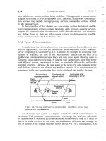
In contrast to a leaf node, a directory node has a number of outgoing edges,
each labeled with a name, as shown in Fig. 5-9. Each node in a naming graph is
considered as yet another entity in a distributed system, and, in particular, has an
196
NAMING
CHAP. 5
associated identifier. A directory node stores a table in which an outgoing edge is
represented as a pair (edge label, node identifier). Such a table is called a direc-
tory table.
Figure 5-9. A general naming graph with a single root node.
The naming graph shown in Fig. 5-9 has one node, namely
no,
which has only
outgoing and no incoming edges. Such a node is called the root (node) of the na-
ming graph. Although it is possible for a naming graph to have several root nodes,
for simplicity, many naming systems have only one. Each path in a naming graph
can be referred to by the sequence of labels corresponding to the edges in that
path, such as
Nt-clabel-I, label-2, , label-n>
where N refers to the first node in the path. Such a sequence is called a path
name. If the first node in a path name is the root of the naming graph, it is called
an"absolute path name. Otherwise, it is called a relative path name.
It is important to realize that names are always organized in a name space. As
a consequence, a name is always defined relative only to a directory node. In this
sense, the term "absolute name" is somewhat misleading. Likewise, the differ-
ence between global and local names can often be confusing. A global name is a
name that denotes the same entity, no matter where that name is used in a system.
In other words, a global name is always interpreted with respect to the same direc-
tory node. In contrast, a local name is a name whose interpretation depends on
where that name is being used. Put differently, a local name is essentially a rela-
tive name whose directory in which it is contained is (implicitly) known. We re-
turn to these issues later when we discuss name resolution.
This description of a naming graph comes close to what is implemented in
many file systems. However, instead of writing the sequence of edge labels to rep-
represent a path name, path names in file systems are generally represented as a
single string in which the labels are separated by a special separator character,
such as a slash
("1").
This character is also used to indicate whether a path name
is absolute. For example, in Fig. 5-9, instead of using no:<home, steen, mbox>,
SEC. 5.3 STRUCTURED NAMING
197
that is, the actual path name, it is common practice to use its string representation
Ihome/steen/mbox. Note also that when there are several paths that lead to the
same node, that node can be represented by different path names. For example,
node n 5 in Fig. 5-9 can be referred to by Ihome/steenlkeys as well as /keys. The
string representation of path names can be equally well applied to naming graphs
other than those used for only file systems. In Plan 9 (Pike et al., 1995), all re-
sources, such as processes, hosts, I/O devices, and network interfaces, are named
in the same fashion as traditional files. This approach is analogous to implement-
ing a single naming graph for all resources in a distributed system.
There are many different ways to organize a name space. As we mentioned,
most name spaces have only a single root node. In many cases, a name space is
also strictly hierarchical in the sense that the naming graph is organized as a tree.
This means that each node except the root has exactly one incoming edge; the root
has no incoming edges. As a consequence, each node also has exactly one associ-
ated (absolute) path name.
The naming graph shown in Fig. 5-9 is an example of directed acyclic graph.
In such an organization, a node can have more than one incoming edge, but the
graph is not permitted to have a cycle. There are also name spaces that do not
have this restriction.
To make matters more concrete, consider the way that files in a traditional
UNIX file system are named. In a naming graph for UNIX, a directory node repres-
ents a file directory, whereas a leaf node represents a file. There is a single root
directory, represented in the naming graph by the root node. The implementation
of the naming graph is an integral part of the complete implementation of the file
system. That implementation consists of a contiguous series of blocks from a logi-
cal disk, generally divided into a boot block, a superblock, a series of index nodes
(called inodes), and file data blocks. See also Crowley (1997), Silberschatz et al.
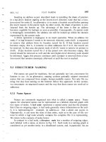
(2005), and Tanenbaum and Woodhull (2006). This organization is shown in
Fig. 5-10.
Figure 5·10. The general organization of the UNIX file system implementation
on a logical disk of contiguous disk blocks.
The boot block is a special block of data and instructions that are automati-
cally loaded into main memory when the system is booted. The boot block is used
to load the operating system into main memory.
198
NAMING
CHAP. 5
The superblock contains information on the entire file system. such as its size,
which blocks on disk are not yet allocated, which inodes are not yet used, and so
on. Inodes are referred to by an index number, starting at number zero, which is
reserved for the inode representing the root directory.
Each inode contains information on where the data of its associated file can
be found on disk. In addition, an inode contains information on its owner, time of
creation and last modification, protection, and the like. Consequently, when given
the index number of an inode, it is possible to access its associated file. Each di-
rectory is implemented as a file as well. This is also the case for the root direc-
tory, which contains a mapping between file names and index numbers of inodes.
It is thus seen that the index number of an inode corresponds to a node identifier
in the naming graph.
5.3.2 Name Resolution
Name spaces offer a convenient mechanism for storing and retrieving infor-
mation about entities by means of names. More generally, given a path name, it
should be possible to look up any information stored in the node referred to by
that name. The process of looking up a name is called name resolution.
To explain how name resolution works, let us consider a path name such as
Ni<label v.label g, .label;». Resolution of this name starts at node N of the na-
ming graph, where the name label} is looked up in the directory table, and which
returns the identifier of the node to which label} refers. Resolution then continues
at the identified node by looking up the name label in its directory table, and so
on. Assuming that the named path actually exists, resolution stops at the last node
referred to by label.; by returning the content of that node.
A name lookup returns the identifier of a node from where the name resolu-
tion process continues. In particular, it is necessary to access the directory table of
the identified node. Consider again a naming graph for a UNIX file system. As
mentioned, a node identifier is implemented as the index number of an inode.
Accessing a directory table means that first the inode has to be read to find out
where the actual data are stored on disk, and then subsequently to read the data
blocks containing the directory table.
Closure Mechanism
Name resolution can take place only if we know how and where to start. In
our example, the starting node was given, and we assumed we had access to its di-
rectory table. Knowing how and where to start name resolution is generally
referred to as a closure mechanism. Essentially, a closure mechanism deals with
selecting the initial node in a name space from which name resolution is to start
(Radia, 1989). What makes closure mechanisms sometimes hard to understand is
SEC. 5.3
STRUCTURED NAMING
199
that they are necessarily partly implicit and may be very different when compar-
ing them to each other.
For example. name resolution in the naming graph for a
UNIX
file system
makes use of the fact that the inode of the root directory is the first inode in the
logical disk representing the file system. Its actual byte offset is calculated from
the values in other fields of the superblock, together with hard-coded information
in the operating system itself on the internal organization of the superblock.
To make this point clear, consider the string representation of a file name such
as Ihomelsteenlmbox. To resolve this name, it is necessary to already have access
to the directory table of the root node of the appropriate naming graph. Being a
root node, the node itself cannot have been looked up unless it is implemented as
a different node in a another naming graph, say G. But in that case, it would have
been necessary to already have access to the root node of G. Consequently, re-
solving a file name requires that some mechanism has already been implemented
by which the resolution process can start.
A completely different example is the use of the string "0031204430784".
Many people will not know what to do with these numbers, unless they are told
that the sequence is a telephone number. That information is enough to start the
resolution process, in particular, by dialing the number. The telephone system
subsequently does the rest.
As a last example, consider the use of global and local names in distributed
systems. A typical example of a local name is an environment variable. For ex-
ample, in UNIX systems, the variable named HOME is used to refer to the home
directory of a user. Each user has its own copy of this variable, which is initialized
to the global, systemwide name corresponding to the user's home directory. The
closure mechanism associated with environment variables ensures that the name
of the variable is properly resolved by looking it up in a user-specific table.
Linking and Mounting
Strongly related to name resolution is the use of aliases. An alias is another
name for the same entity. An environment variable is an example of an alias. In
terms of naming graphs, there are basically two different ways to implement an
alias. The first approach is to simply allow multiple absolute paths names to refer
to the same node in a naming graph. This approach is illustrated in Fig. 5-9, in
which node
n
s can be referred to by two different path names. In UNIXterminol-
ogy, both path names /keys and /homelsteen/keys in Fig. 5-9 are called hard links
to node
ns.
The second approach is to represent an entity by a leaf node, say N, but in-
stead of storing the address or state of that entity, the node stores an absolute path
name. When first resolving an absolute path name that leads to
N,
name resolution
will return the path name stored in N, at which point it can continue with resolving
that new path name. This principle corresponds to the use of symbolic links
in
200
NAMING
CHAP. 5
UNIX file systems, and is illustrated in Fig. 5-11. In this example, the path name
/home/steen/keys, which refers to a node containing the absolute path name /keys,
is a symbolic link to node
n
5 .
Figure 5-11. The concept of a symbolic link explained in a naming graph.
Name resolution as described so far takes place completely within a single
name space. However, name resolution can also be used to merge different name
spaces in a transparent way. Let us first consider a mounted file system. In terms
of our naming model, a mounted file system corresponds to letting a directory
node store the identifier of a directory node from a different name space, which
we refer to as a foreign name space. The directory node storing the node identifier
is called a mount point. Accordingly, the directory node in the foreign name
space is called a mounting point. Normally, the mounting point is the root of a
name space. During name resolution, the mounting point is ,looked up and resolu-
tion proceeds by accessing its directory table.
The principle of mounting can be generalized to other name spaces as well. In
particular, what is needed is a directory node that acts as a mount point and stores
all the necessary information for identifying and accessing the mounting point in
the foreign name space. This approach is followed in many distributed file sys-
tems.
Consider a collection of name spaces that is distributed across different ma-
chines. In particular, each name space is implemented by a different server, each
possibly running on a separate machine. Consequently. if we want to mount a
foreign name space NS 2 into a name space NS 1, it may be necessary to communi-
cate over a network with the server of NS
2,
as that server may be running on a
different machine than the server for NS i- To mount a foreign name space in a
distributed system requires at least the following information:
1. The name of an access protocol.
2. The name of the server.
3. The name of the mounting point in the foreign name space.
SEC. 5.3
STRUCTURED NAMING
201
Note that each of these names needs to be resolved. The name of an access proto-
col needs to be resolved to the implementation of a protocol by which communi-
cation with the server of the foreign name space can take place. The name of the
server needs to be resolved to an address where that server can be reached. As the
last part in name resolution, the name of the mounting point needs to be resolved
to a node identifier in the foreign name space.
In nondistributed systems, none of the three points may actually be needed.
For example, in UNIX, there is no access protocol and no server. Also, the name
of the mounting point is not necessary, as it is simply the root directory of the
foreign name space.
The name of the mounting point is to be resolved by the server of the foreign
name space. However, we also need name spaces and implementations for the ac-
cess protocol and the server name. One possibility is to represent the three names
listed above as a URL.
To make matters concrete, consider a situation in which a user with a laptop
computer wants to access files that are stored on a remote file server. The client
machine and the file server are both configured with Sun's Network File System
(NFS), which we will discuss in detail in Chap. 11. NFS is a distributed file sys-
tem that comes with a protocol that describes precisely how a client can access a
file stored on a (remote) NFS file server. In particular, to allow NFS to work a-
cross the Internet, a client can specify exactly which file it wants to access by
means of an NFS URL, for example, nfs:l/flits.cs. vu.nl//homelsteen. This URL
names a file (which happens to be a directory) called /home/steen on an NFS file
serverflits.cs. vu.nl, which can be accessed by a client by means of the NFS proto-
col (Shepler et aI., 2003).
The name nfs is a well-known name in the sense that worldwide agreement
exists on how to interpret that name. Given that we are dealing with a URL, the
name nfs will be resolved to an implementation of the NFS protocol. The server
name is resolved to its address using DNS, which is discussed in a later section.
As we said, /home/steen is resolved by the server of the foreign name space.
The organization of a file system on the client machine is partly shown in
Fig. 5-12. The root directory has a number of user-defined entries, including a
subdirectory called Iremote. This subdirectory is intended to include mount points
for foreign name spaces such as the user's home directory at the Vrije Universi-
teit. To this end, a directory node named Iremote/vu is used to store the URL
nfs:l/flits.cs. vu.nll/homelsteen.
Now consider the name /remotelvulmbox. This name is resolved by starting
in the root directory on the client's machine and continues until the node Ire-
mote/vu is reached. The process of name resolution then continues by returning
the URL nfs:l/flits.cs. vu.nl//homelsteen, in turn leading the client machine to con-
tact the file serverflits.cs. vu.nl by means of the NFS protocol, and to subsequently
access directory /home/steen. Name resolution can then be continued by reading
the file named mbox in that directory, after which the resolution process stops.
202
NAMING
CHAP. 5
Figure 5-12. Mounting remote name spaces through a specific access protocol.
Distributed systems that allow mounting a remote file system as just described
allow a client machine to, for example, execute the following commands:
cd
/remote/vu
Is -I
which subsequently lists the files in the directory /home/steen on the remote file
server. The beauty of all this is that the user is spared the details of the actual ac-
cess to the remote server. Ideally, only some loss in performance is noticed com-
pared to accessing locally-available files. In effect, to the client it appears that the
name space rooted on the local machine, and the one rooted at /home/steen on the
remote machine, form a single name space.
5.3.3 The Implementation of a Name Space
A name space forms the heart of a naming service, that is, a service that
allows users and processes to add, remove, and look up names. A naming service
is implemented by name servers. If a distributed system is restricted to a local-
area network, it is often feasible to implement a naming service by means of only
a single name server. However, in large-scale distributed systems with many enti-
ties, possibly spread across a large geographical area, it is necessary to distribute
the implementation of a name space over multiple name servers.
SEC. 5.3
STRUCTURED NAMING
203
Name Space Distribution
Name spaces for a large-scale, possibly worldwide distributed system, are
usually organized hierarchically. As before, assume such a name space has only a
single root node. To effectively implement such a name space, it is convenient to
partition it into logical layers. Cheriton and Mann (1989) distinguish the following
three layers.
The global layer is formed by highest-level nodes, that is, the root node and
other directory nodes logically close to the root, namely its children. Nodes in the
global layer are often characterized by their stability, in the sense that directory
tables are rarely changed. Such nodes may represent organizations or groups of
organizations, for which names are stored in the name space.
The administrational layer is formed by directory nodes that together are
managed within a single organization. A characteristic feature of the directory
nodes in the administrational layer is that they represent groups of entities that
belong to the same organization or administrational unit. For example, there may
be a directory node for each' department in an organization, or a directory node
from which all hosts can be found. Another directory node may be used as the
starting point for naming all users, and so forth. The nodes in the administrational
layer are relatively stable, although changes generally occur more frequently than
to nodes in the global layer.
Finally, the managerial layer consists of nodes that may typically change
regularly. For example, nodes representing hosts in the local network belong to
this layer. For the same reason, the layer includes nodes representing shared files
such as those for libraries or binaries. Another important class of nodes includes
those that represent user-defined directories and files. In contrast to the global and
administrational layer, the nodes in the managerial layer are maintained not only
by system administrators, but also by individual end users of a distributed system.
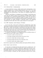
To make matters more concrete, Fig. 5-13 shows an example of the parti-
tioning of part of the DNS name space, including the names of files within an
organization that can be accessed through the Internet, for example, Web pages
and transferable files. The name space is divided into nonoverlapping parts, called
zones in DNS (Mockapetris, 1987). A zone is a part of the name space that is im-
plemented by a separate name server. Some of these zones are illustrated in
Fig. 5-13.
If we take a look at availability and performance, name servers in each layer
have to meet different requirements. High availability is especially critical for
name servers in the global layer. If a name server fails, a large part of the name
space will be unreachable because name resolution cannot proceed beyond the
failing server.
Performance is somewhat subtle. Due to the low rate of change of nodes in
the global layer, the results of lookup operations generally remain valid for a long
time. Consequently, those results can be effectively cached (i.e., stored locally) by
204
NAMING
CHAP. 5
Figure 5-13. An example partitioning of the DNS name space, including
Internet-accessible files, into three layers.
the clients. The next time the same lookup operation is performed, the results can
be retrieved from the client's cache instead of letting the name server return the
results. As a result, name servers in the global layer do not have to respond
quickly to a single lookup request. On the other hand, throughput may be impor-
tant, especially in large-scale systems with millions of users.
The availability and performance requirements for name servers in the global
layer can be met by replicating servers, in combination with client-side caching.
As we discuss in Chap. 7, updates in this layer generally do not have to come into
effect immediately, making it much easier to keep replicas consistent.
Availability for a name server in the administrational layer is primarily impor-
tant for clients in the same organization as the name server. If the name server
fails, many resources within the organization become unreachable because they
cannot be looked up. On the other hand, it may be less important that resources in
an organization are temporarily unreachable for users outside that organization.
With respect to performance, name servers in the administrational layer have
similar characteristics as those in the global layer. Because changes to nodes do
not occur all that often, caching lookup results can be highly effective, making
performance less critical. However, in contrast to the global layer, the administra-
tionallayer should take care that lookup results are returned within a few millisec-
SEC. 5.3
STRUCTURED NAMING
205
onds, either directly from the server or from the client's local cache. Likewise,
updates should generally be processed quicker than those of the global layer. For
example, it is unacceptable that an account for a new user takes hours to become
effective.
These requirements can often be met by using high-performance machines to
run name servers. In addition, client-side caching should be applied, combined
with replication for increased overall availability.
Availability requirements for name servers at the managerial level are gener-
ally less demanding. In particular, it often suffices to use a single (dedicated) ma-
chine to run name servers at the risk of temporary unavailability. However, per-
formance is crucial. Users expect operations to take place immediately. Because
updates occur regularly, client-side caching is often less effective, unless special
measures are taken, which we discuss in Chap. 7.
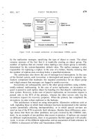
Figure 5-14. A comparison between name servers for implementing nodes from
a large-scale name space partitioned into a global layer, an administrational
layer, and a managerial layer.
A comparison between name servers at different layers is shown in Fig. 5-14.
In distributed systems, name servers in the global and administrational layer are
the most difficult to implement. Difficulties are caused by replication and cach-
ing, which are needed for availability and performance, but which also introduce
consistency problems. Some of the problems are aggravated by the fact that
caches and replicas are spread across a wide-area network, which introduces long
communication delays thereby making synchronization even harder. Replication
and caching are discussed extensively in Chap. 7.
Implementation of Name Resolution
The distribution of a name space across multiple name servers affects the
implementation of name resolution. To explain the implementation of name reso-
lution in large-scale name services, we assume for the moment that name servers
are not replicated and that no client-side caches are used. Each client has access to
206
NAMING
CHAP. 5
a local name resolver, which is responsible for ensuring that the name resolution
process is carried out. Referring to Fig. 5-13, assume the (absolute) path name
root: «nl,
VU, CS,
ftp,
pub, globe, index.html>
is to be resolved. Using a URL notation, this path name would correspond to
. vu.nl/pub/globe/index.html. There are now two ways to implement
name resolution.
In iterative name resolution, a name resolver hands over the complete name
to the root name server. It is assumed that the address where the root server can be
contacted is well known. The root server will resolve the path name as far as it
can, and return the result to the client. In our example, the root server can resolve
only the label nl, for which it will return the address of the associated name ser-
ver.
At that point. the client passes the remaining path name (i.e., nl:
<VU,
cs, jtp,
pub, globe, index.html> to that name server. This server can resolve only the
label
VU,
and returns the address of the associated name server, along with the
remaining path name vu:<cs, ftp, pub, globe, index.html>.
The client's name resolver will then contact this next name server, which
responds by resolving the label cs, and subsequently also ftp, returning the address
of the FTP server along with the path name ftp:<pub, globe, index.html>. The
client then contacts the FTP server, requesting it to resolve the last part of the ori-
ginal path name. The FTP server will subsequently resolve the labels pub. globe,
and index.html, and transfer the requested file (in this case using FTP). This proc-
ess of iterative name resolution is shown in Fig. 5-15. (The notation #<cs> is
used to indicate the address of the server responsible for handling the node
referred to by <cs>.)
Figure 5-15. The principle of iterative name resolution.
SEC. 5.3
STRUCTURED NAMING 207
In practice, the last step, namely contacting the FTP server and requesting it
to transfer the file with path name
ftp
i-cpub, globe, index.himl», is carried out
separately by the client process. In other words, the client would normally hand
only the path name root: «nl,
VU, CS,
ftp>
to the name resolver, from which it
would expect the address where it can contact the
FTP
server, as is also shown in
Fig. 5-15.
An alternative to iterative name resolution is to use recursion during name
resolution. Instead of returning each intermediate result back to the client's name
resolver, with recursive name resolution, a name server passes the result to the
next name server it finds. So, for example, when the root name server finds the
address of the name server implementing the node named nl, it requests that name
server to resolve the path name nl:<vu,
CS,
ftp, pub, globe, index.html>. Using
recursive name resolution as well, this next server will resolve the complete path
and eventually return the file index.html to the root server, which, in tum, will
pass that file to the client's name resolver.
Recursive name resolution is shown in Fig. 5-16. As in iterative name resolu-
tion, the last resolution step (contacting the FTP server and asking it to transfer
the indicated file) is generally carried out as a separate process by the client.
Figure 5-16. The principle of recursive name resolution.
The main drawback of recursive name resolution is that it puts a higher per-
formance demand on each name server. Basically, a name server is required to
handle the complete resolution of a path name, although it may do so in coopera-
tion with other name servers. This additional burden is generally so high that
name servers in the global layer of a name space support only iterative name reso-
lution.
There are two important advantages to recursive name resolution. The first
advantage is that caching results is more effective compared to iterative name
resolution. The second advantage is that communication costs may be reduced. To
208
NAMING
CHAP. 5
explain these advantages, assume that a client's name resolver will accept path
names referring only to nodes in the global or administrational layer of the name
space. To resolve that part ofa path name that corresponds to nodes in the manag-
erial layer, a client will separately contact the name server returned by its name
resolver, as we discussed above.
Recursive name resolution allows each name server to gradually learn the ad-
dress of each name server responsible for implementing lower-level nodes. As a
result, caching can be effectively used to enhance performance. For example,
when the root server is requested to resolve the path name root:<nl, vu, cs,
ftp>,
it will eventually get the address of the name server implementing the node
referred to by that path name. To come to that point, the name server for the nl
node has to look up the address of the name server for the vu node, whereas the
latter has to look up the address of the name server handling the cs node.
Because changes to nodes in the global and administrational layer do not
occur often, the root name server can effectively cache the returned address.
Moreover, because the address is also returned, by recursion, to the name server
responsible for implementing the vu node and to the one implementing the nl
node, it might as well be cached at those servers too.
Likewise, the results of intermediate name lookups can also be returned and
cached. For example, the server for the nl node will have to look up the address of
the vu node server. That address can be returned to the root server when the nl
server returns the result of the original name lookup. A complete overview of the
resolution process, and the results that can be cached by each name server is
shown in Fig. 5-17.
Figure 5-17. Recursive name resolution of
«nl,
l'U, CS.
jtp>. Name servers
cache intermediate results for subsequent lookups.
The main benefit of this approach is that, eventually. lookup operations can be
handled quite efficiently. For example, suppose that another client later requests
SEC. 5.3
STRUCTURED NAMING
209
resolution of the path name root:<nl,
Vii,
cs, flits>. This name is passed to the
root, which can immediately forward it to the name server for the cs node, and re-
quest it to resolve the remaining path name cs:<jlits>.
With iterative name resolution, caching is necessarily restricted to the client's
name resolver. Consequently, if a client
A
requests the resolution of a name, and
another client B later requests that same name to be resolved, name resolution will
have to pass through the same name servers as was done for client A. As a com-
promise, many organizations use a local, intermediate name server that is shared
by all clients. This local name server handles all naming requests and caches re-
sults. Such an intermediate server is also convenient from a management point of
view. For example, only that server needs to know where the root name server is
located; other machines do not require this information.
The second advantage of recursive name resolution is that it is often cheaper
with respect to communication. Again, consider the resolution of the path name
root:<nl, vu, cs, ftp> and assume the client is located in San Francisco. Assuming
that the client knows the address of the server for the nl node, with recursive name
resolution, communication follows the route from the client's host in San Fran-
cisco to the nl server in The Netherlands, shown as R 1 in Fig. 5-18. From there
on, communication is subsequently needed between the nl server and the name
server of the Vrije Universiteit on the university campus in Amsterdam, The
Netherlands. This communication is shown as R 2. Finally, communication is
needed between the vu server and the name server in the Computer Science
Department, shown as R 3. The route for the reply is the same, but in the opposite
direction. Clearly, communication costs are dictated by the message exchange be-
tween the client's host and the nl server.
In contrast, with iterative name resolution, the client's host has to communi-
cate separately with the nl server, the vu server, and the cs server, of which the
total costs may be roughly three times that of recursive name resolution. The
arrows in Fig. 5-18 labeled /1, /2, and /3 show the communication path for itera-
tive name resolution.
5.3.4 Example: The Domain Name System
One of the largest distributed naming services in use today is the Internet
Domain Name System (DNS). DNS is primarily used for looking up IP addresses
of hosts and mail servers. In the following pages, we concentrate on the organiza-
tion of the DNS name space, and the information stored in its nodes. Also, we
take a closer look at the actual implementation of DNS. More information can be
found in Mockapetris (1987) and Albitz and Liu (2001). A recent assessment of
DNS, notably concerning whether it still fits the needs of the current Internet, can
be found in Levien (2005). From this report, one can draw the somewhat surpris-
ing conclusion that even after more than 30 years, DNS gives no indication that it
210
NAMING
CHAP. 5
Figure 5-18. The comparison between recursive and iterative name resolution
with respect to communication costs.
needs to be replaced. We would argue that the main cause lies in the designer's
deep understanding of how to keep matters simple. Practice in other fields of dis-
tributed systems indicates that not many are gifted with such an understanding.
The DNS Name Space
The DNS name space is hierarchically organized as a rooted tree. A label is a
case-insensitive string made up of alphanumeric characters. A label has a max-
imum length of 63 characters; the length of a complete path name is restricted to
255 characters. The string representation of a path name consists of listing its la-
bels, starting with the rightmost one, and separating the labels by a dot (H. "). The
root is represented by a dot. So, for example, the path name root: <nl,
VU,
cs,
flits>, is represented by the string flits.cs. vu.nl., which includes the rightmost dot
to indicate the root node. We generally omit this dot for readability.
Because each node in the DNS name space has exactly one incoming edge
(with the exception of the root node, which has no incoming edges), the label at-
tached toa node's incoming edge is also used as the name for that node. A subtree
is called a domain; a path name to its root node is called a domain name. Note
that, just like a path name, a domain name can be either absolute or relative.
The contents of a node is formed by a collection of resource records. There
are different types of resource records. The major ones are shown in Fig. 5-19.
A node in the DNS name space often will represent several entities at the
same time. For example, a domain name such as vu.nl is used to represent a do-
main and a zone. In this case, the domain is implemented by means of several
(nonoverlapping) zones.
An SOA (start of authority) resource record contains information such as an
e-mail address of the system administrator responsible for the represented zone.
the name of the host where data on the zone can be fetched, and so on.
SEC. 5.3 STRUCTURED NAMING 211
Figure 5-19. The most important types of resource records forming the contents
of nodes in the DNS name space.
An A (address) record, represents a particular host in the Internet. The A
record contains an IP address for that host to allow communication. If a host has
several IP addresses, as is the case with multi-homed machines, the node will con-
tain an A record for each address.
Another type of record is the
MX
(mail exchange) record, which is like a sym-
bolic link to a node representing a mail server. For example, the node representing
the domain cs.vu.nl has an MX record containing the name zephyr.cs.vu.nl, which
refers to a mail server. That server will handle all incoming mail addressed to
users in the cs. vu.nl domain. There may be several MX records stored in a node.
Related to MX records are SRV records, which contain the name of a server
for a specific service. SRV records are defined in Gulbrandsen (2000). The ser-
vice itself is identified by means of a name along with the name of a protocol. For
example, the Web server in the cs. vu.nl domain could be named by means of an
SRV record such as .Jutp.ctcp.cs.vu.nl, This record would then refer to the actual
name of the server (which is soling.cs. vu.nl). An important advantage of SRV
records is that clients need no longer know the DNS name of the host providing a
specific service. Instead, only service names need to be standardized, after which
the providing host can be looked up.
Nodes that represent a zone, contain one or more NS (name server) records.
Like
MX
records, an
NS
record contains the name of a name server that imple-
ments the zone represented by the node. In principle, each node in the name space
can store an NS record referring to the name server that implements it. However,
as we discuss below, the implementation of the DNS name space is such that only
nodes representing zones need to store NS records.
DNS distinguishes aliases from what are called canonical names. Each host
is assumed to have a canonical, or primary name. An alias is implemented by
212
NAMING
CHAP. 5
means of node storing a CNAME record containing the canonical name of a host.
The name of the node storing such a record is thus the same as a symbolic link, as
was shown in Fig. 5-
J J.
DNS maintains an inverse mapping of IP addresses to host names by means of
PTR
(pointer) records. To accommodate the lookups of host names when given
only an IP address, DNS maintains a domain named in-addr.arpa, which contains
nodes that represent Internet hosts and which are named by the IP address of the
represented host. For example, host
tVww.cs.\'u.nl
has IP address 130.37.20.20.
DNS creates a node named 20.20.37.130.in-addr.mpa, which is used to store the
canonical name of that host (which happens to be
soling.cs.
vu.nl
i
in a
PTR
record.
The last two record types are
HINFO
records and
TXT
records. An
HINFO
(host info) record is used to store additional information on a host such as its ma-
chine type and operating system. In a similar fashion,
TXT
records are used for
any other kind of data that a user finds useful to store about the entity represented
by the node.
DNS Implementation
In essence, the DNS name space can be divided into a global layer and an
administrational layer as shown in Fig. 5-13. The managerial layer, which is gen-
erally formed by local file systems, is formally not part of DNS and is therefore
also not managed by it.
Each zone is implemented by a name server, which is virtually always repli-
cated for availability. Updates for a zone are normally handled by the primary
name server. Updates take place by modifying the DNS database local to the pri-
mary server. Secondary name servers do not access the database directly, but, in-
stead, request the primary server to transfer its content. The latter is called a zone
transfer in DNS terminology.
A DNS database is implemented as a (small) collection of files, of which the
most important one contains all the resource records for all the nodes in a particu-
lar zone. This approach allows nodes to be simply identified by means of their do-
main name, by which the notion of a node identifier reduces to an (implicit) index
into a file.
To better understand these implementation issues, Fig. 5-20 shows a small
part of the file that contains most of the information for the cs.vu.nl domain (the
file has been edited for simplicity). The file shows the contents of several nodes
that are part of the
cs. vu.nl
domain, where each node is identified by means of its
domain name.
The node
cs.vu.nl
represents the domain as well as the zone. Its
SOA
resource
record contains specific information on the validity of this file. which will not
concern us further. There are four name servers for this zone, referred to by their
canonical host names in the
NS
records. The
TXT
record is used to give some
SEC. 5.3
STRUCTURED NAMING
213
additional information on this zone, but cannot be automatically processed by any
name server. Furthermore, there is a single mail server that can handle incoming
mail addressed to users in this domain. The number preceding the name of a mail
server specifies a selection priority. A sending mail server should always first at-
tempt to contact the mail server with the lowest number.
Figure 5-20. An excerpt from the DNS database for the zone
cs. vU.1l1.
The host
star.cs. vu.nl
operates as a name server for this zone. Name servers
are critical to any naming service. What can be seen about this name server is that
additional robustness has been created by giving two separate network interfaces,
214
NAMING
CHAP. 5
each represented by a separate A resource record. In this way, the effects of a bro-
ken network link can be somewhat alleviated as the server will remain accessible.
The next four lines (for zephyr.cs. vu.nl) give the necessary information about
one of the department's mail servers. Note that this mail server is also backed up
by another mail server, whose path is tornado.cs. vu.nl,
The next six lines show a typical configuration in which the department's
Web server, as well as the department's FTP server are implemented by a single
machine, called
soling. cs. vu. nl.
By executing both servers on the same machine
(and essentially using that machine only for Internet services and not anything
else), system management becomes easier. For example, both servers will have
the same view of the file system, and for efficiency, part of the file system may be
implemented on soling.cs.vu.nl, This approach is often applied in the case of
WWW and FTP services.
The following two lines show information on one of the department's older
server clusters. In this case, it tells us that the address 130.37.198.0 is associated
with the host name vucs-dasl.cs.vu.nl,
The next four lines show information on two major printers connected to the
local network. Note that addresses in the range 192.168.0.0 to 192.168.255.255
are private: they can be accessed only from inside the local network and are not
accessible from an arbitrary Internet host.
Figure 5-21.
Part
of the description for the vu.nl domain which contains the
cs. vu.nl
domain.
Because the cs.vu.nl domain is implemented as a single zone. Fig. 5-20 does
not include references to other zones. The way to refer to nodes in a subdomain
that are implemented in a different zone is shown in Fig. 5-21. What needs to be
done is to specify a name server for the subdomain by simply giving its domain
name and IP address. When resolving a name for a node that lies in the cs.vu.nl
domain, name resolution will continue at a certain point by reading the DNS data-
base stored by the name server for the cs. vu.nl domain.
SEC. 5.3
STRUCTURED NAMING
215
Decentralized DNS Implementations
The implementation of DNS we described so far is the standard one. It fol-
lows a hierarchy of servers with 13 well-known root servers and ending in mil-
lions of servers at the leaves. An important observation is that higher-level nodes
receive many more requests than lower-level nodes. Only by caching the name-
to-address bindings of these higher levels is it possible to avoid sending requests
to them and thus swamping them.
These scalability problems can be avoided alt-ogetherwith fully decentralized
solutions. In particular, we can compute the hash of a DNS name, and subse-
quently take that hash as a key value to be looked up in a distributed-hash table or
a hierarchical location service with a fully partitioned root node. The obvious
drawback of this approach is that we lose the structure of the original name. This
loss may prevent efficient implementations of, for example, finding all children in
a specific domain.
On the other hand, there are many advantages to mapping DNS to a DHT-
based implementation, notably its scalability. As argued by Walfish et al. (2004),
when there is a need for many names, using identifiers as a semantic-free way of
accessing data will allow different systems to make use of a single naming sys-
tem. The reason is simple: by now it is well understood how a huge collection of
(flat) names can be efficiently supported. What needs to be done is to maintain the
mapping of identifier-to-name information, where in this case a name may come
from the DNS space, be a URL, and so on. Using identifiers can be made easier
by letting users or organizations use a strict local name space. The latter is com-
pletely analogous to maintaining a private setting of environment variables on a
computer.
Mapping DNS onto DHT-based peer-to-peer systems has been explored in
CoDoNS (Ramasubramanian and Sirer, 2004a). They used a DHT-based system
in which the prefixes of keys are used to route to a node. To explain, consider the
case that each digit from an identifier is taken from the set { 0, ,
b-l },
where
b
is the base number. For example, in Chord,
b
=
2. If we assume that
b
=
4, then
consider a node whose identifier is 3210. In their system, this node is assumed to
keep a routing table of nodes having the following identifiers:
no:
a node whose identifier has prefix 0
n
1 :
a node whose identifier has prefix 1
n
2:
a node whose identifier has prefix 2
n 30: a node whose identifier has prefix 30
n
31 :
a node whose identifier has prefix 31
n
33:
a node whose identifier has prefix 33
n 320: a node whose identifier has prefix320
n 322: a node whose identifier has prefix 322
n 323: a node whose identifier has prefix 323
216
NAMING
CHAP. 5
where
N
is the number of nodes in the network and
a
is the parameter in the Zipf
distribution.
This formula allows to take informed decisions on which DNS records should
be replicated. To make matters concrete, consider the case that b
=
32 and
a
=
0.9. Then, in a network with 10,000 nodes and 1,000,000 DNS records, and
trying to achieve an average of C=1 hop only when doing a lookup, we will have
that
Xo
=
0.0000701674, meaning that only the 70 most popular DNS records
Node 3210 is responsible for handling keys that have prefix 321. If it receives a
lookup request for key 3123, it will forward it to node 113b which, in turn, will see
whether it needs to forward it to a node whose identifier has prefix 312. (We
should note that each node maintains two other lists that it can use for routing if it
misses an entry in its routing table.) Details of this approach can be found for Pas-
try (Rowstron and Druschel, 2001) and Tapestry (Zhao et al., 2004).
Returning to CoDoNS, a node responsible for key
k
stores the DNS resource
records associated with domain name that hashes to k. The interesting part, how-
ever, is that CoDoNS attempts to minimize the number of hops in routing a re-
quest by replicating resource records. The principle strategy is simple: node 3210
will replicate its content to nodes having prefix 321. Such a replication will re-
duce each routing path ending in node 3210 by one hop. Of course, this replica-
tion can be applied again to all nodes having prefix 32, and so on.
When a DNS record gets replicated to all nodes with
i
matching prefixes, it is
said to be replicated at level
i.
Note that a record replicated at level
i
(generally)
requires i lookup steps to be found. However, there is a trade-off between the
level of replication and the use of network and node resources. What CoDoNS
does is replicate to the extent that the resulting aggregate lookup latency is less
than a given constant C.
More specifically, think for a moment about the frequency distribution of the
queries. Imagine ranking the lookup queries by how often a specific key is re-
quested putting the most requested key in first position. The distribution of the
lookups is said to be Zipf-like if the frequency of the n-th ranked item is propor-
tional to
l/n
a,
with
a
close to 1. George Zipf was a Harvard linguist who
discovered this distribution while studying word-use frequencies in a natural lan-
guage. However, as it turns out, it also applies among many other things, to the
population of cities, size of earthquakes, top-income distributions, revenues of
corporations, and, perhaps no longer surprisingly, DNS queries (Jung et al., 2002).
Now, if Xi is the fraction of most popular records that are to be replicated at
level
i,
then Ramasubramanian and Sirer (2004b) show that Xi can be expressed
by the following formula (for our purposes, only the fact that this formula exists is
actually important; we will see how to use it shortly):
SEC. 5.3
STRUCTURED NAMING
217
should be replicated everywhere. Likewise, with x
I
=
0.00330605, the 3306 next
most popular records should be replicated at level 1. Of course, it is required that
Xi
<
1. In this example, Xl
=
0.155769 and X3 > 1, so that only the next most
popular 155,769 records get replicated and all the others or not. Nevertheless, on
average, a single hop is enough to find a requested DNS record.
S.4 ATTRIBUTE-BASED NAMING
Flat and structured names generally provide a unique and location-indepen-
dent way of referring to entities. Moreover, structured names have been partly
designed to provide a human-friendly way to name entities so that they can be
conveniently accessed. In most cases, it is assumed that the name refers to only a
single entity. However, location independence and human friendliness are not the
only criterion for naming entities. In particular, as more information is being made
available it becomes important to effectively search for entities. This approach re-
quires that a user can provide merely a description of what he is looking for.
There are many ways in which descriptions can be provided, but a popular
one in distributed systems is to describe an entity in terms of (attribute, value)
pairs, generally referred to as attribute-based naming. In this approach, an enti-
ty is assumed to have an associated collection of attributes. Each attribute says
something about that entity. By specifying which values a specific attribute should
have, a user essentially constrains the set of entities that he is interested in. It is up
to the naming system to return one or more entities that meet the user's descrip-
tion. In this section we take a closer look at attribute-based naming systems.
5.4.1 Directory Services
Attribute-based naming systems are also known as directory services, where-
as systems that support structured naming are generally called naming systems.
With directory services, entities have a set of associated attributes that can be
used for searching. In some cases, the choice of attributes can be relatively sim-
ple. For example, in an e-mail system, messages can be tagged with attributes for
the sender, recipient, subject, and so on. However, even in the case of e-mail,
matters become difficult when other types of descriptors are needed, as is illus-
trated by the difficulty of developing filters that will allow only certain messages
(based on their descriptors) to be passed through.
What it all boils down to is that designing an appropriate set of attributes is
not trivial. In most cases, attribute design has to be done manually. Even if there
is consensus on the set of attributes to use, practice shows that setting the values
consistently by a diverse group of people is a problem by itself, as many will have
experienced when accessing music and video databases on the Internet.
218
NAMING
CHAP. 5
To alleviate some of these problems, research has been conducted on unifying
the ways that resources can be described. In the context of distributed systems,
one particularly relevant development is the resource description framework
(RDF). Fundamental to the RDF model is that resources are described as triplets
consisting of a subject, a predicate, and an object. For example, (Person, name,
Alice) describes a resource Person whose name is Alice. In RDF, each subject,
predicate, or object can be a resource itself. This means that Alice may be imple-
mented as reference to a file that can be subsequently retrieved. In the case of a
predicate, such a resource could contain a textual description of that predicate. Of
course, resources associated with subjects and objects could be anything. Refer-
ences in RDF are essentially URLs.
If resource descriptions are stored, it becomes possible to query that storage in
a way that is common for many attributed-based naming systems. For example, an
application could ask for the information associated with a person named Alice.
Such a query would return a reference to the person resource associated with
Alice. This resource can then subsequently be fetched by the application. More in-
formation on RDF can be found in Manola and Miller (2004).
In this example, the resource descriptions are stored at a central location.
There is no reason why the resources should reside at the same location as well.
However, not having the descriptions in the same place may incur a serious per-
formance problem. Unlike structured naming systems, looking up values in an at-
tribute-based naming system essentially requires an exhaustive search through all
descriptors. When considering performance, such a search is less of problem with-
in a single data store, but separate techniques need to be applied when the data is
distributed across multiple, potentially dispersed computers. In the following, we
will take a look at different approaches to solving this problem in distributed sys-
tems.
5.4.2 Hierarchical Implementations: LDAP
A common approach to tackling distributed directory services is to combine
structured naming with attribute-based naming. This approach has been widely
adopted, for example, in Microsoft's Active Directory service and other systems.
Many of these systems use, or rely on the lightweight directory access protocol
commonly referred simply as LDAP. The LDAP directory service has been
derived from OS1's X.500 directory service. As with many OSI services, the qual-
ity of their associated implementations hindered widespread use, and simplifica-
tions were needed to make it useful. Detailed information on LDAP can be found
in Arkills (2003).
Conceptually, an LDAP directory service consists of a number of records,
usually referred to as directory entries. A directory entry is comparable to a re-
source record in DNS. Each record is made up of a collection of (attribute. value)
pairs, where each attribute has an associated type. A distinction is made between
SEC. 5.4 ATIRIBUTE-BASED NAMING
219
single-valued attributes and multiple-valued attributes. The latter typically repres-
ent arrays and lists. As an example, a simple directory entry identifying the net-
work addresses of some general servers from Fig. 5-20 is shown in Fig. 5-22.
Figure 5-22. A simple example of an LDAP directory entry using LDAP na-
ming conventions.
In our example, we have used a naming convention described in the LDAP
standards, which applies to the first five attributes. The attributes Organization
and Organization Unit describe, respectively, the organization and the department
associated with the data that are stored in the record. Likewise, the attributes
Locality and Country provide additional information on where the entry is stored.
The CommonName attribute is often used as an (ambiguous) name to identify an
entry within a limited part of the directory. For example, the name "Main server"
may be enough to find our example entry given the specific values for the other
four attributes Country, Locality, Organization, and Organizational Unit. In our
example, only attribute Mail Servers has multiple values associated with it. All
other attributes have only a single value.
The collection of all directory entries in an LDAP directory service is called a
directory information base (DIB). An important aspect of a DIB is that each
record is uniquely named so that it can be looked up. Such a globally unique name
appears as a sequence of naming attributes in each record. Each naming attribute
is called a relative distinguished name, or RDN for short. In our example in
Fig: 5-22, the first five attributes are all naming attributes. Using the conventional
abbreviations for representing naming attributes in LDAP, as shown in Fig. 5-22,
the attributes Country, Organization, and Organizational Unit could be used to
form the globally unique name
analogous to the DNS name nl. vu.cs,
As in DNS, the use of globally unique names by listing RDNs in sequence,
leads to a hierarchy of the collection of directory entries, which is referred to as a