DISTRIBUTED SYSTEMS principles and paradigms Second Edition phần 3 pptx
Bạn đang xem bản rút gọn của tài liệu. Xem và tải ngay bản đầy đủ của tài liệu tại đây (1.29 MB, 71 trang )
124
COMMUNICATION
CHAP. 4
as a middleware service, without being modified. This approach is somewhat an-
alogous to offering UDP at the transport level. Likewise, middleware communica-
tion services may include message-passing services comparable to those offered
by the transport layer.
In the remainder of this chapter, we concentrate on four high-level middle-
ware communication services: remote procedure calls, message queuing services,
support for communication of continuous media through streams, and multicast-
ing. Before doing so, there are other general criteria for distinguishing (middle-
ware) communication which we discuss next.
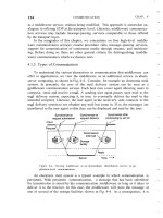
4.1.2 Types of Communication
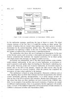
To understand the various alternatives in communication that middleware can
offer to applications, we view the middleware as an additional service in client-
server computing, as shown in Fig. 4-4. Consider, for example an electronic mail
system. In principle, the core of the mail delivery system can be seen as a
middleware communication service. Each host runs a user agent allowing users to
compose, send, and receive e-mail. A sending user agent passes such mail to the
mail delivery system, expecting it, in tum, to eventually deliver the mail to the
intended recipient. Likewise, the user agent at the receiver's side connects to the
mail delivery system to see whether any mail has come in. If so, the messages are
transferred to the user agent so that they can be displayed and read by the user.
Figure 4-4. Viewing middleware as an intermediate (distributed) service in ap-
plication-level communication.
An electronic mail system is a typical example in which communication is
persistent. With persistent communication, a message that has been submitted
for transmission is stored by the communication middleware as long as it takes to
deliver it to the receiver. In this case, the middleware will store the message at
one or several of the storage facilities shown in Fig. 4-4. As a consequence, it is
SEC. 4.1
FUNDAMENTALS
125
not necessary for the sending application to continue execution after submitting
the message. Likewise, the receiving application need not be executing when the
message is submitted.
In contrast, with transient communication, a message is stored by the com-
munication system only as long as the sending and receiving application are exe-
cuting. More precisely, in terms of Fig. 4-4, the middleware cannot deliver a mes-
sage due to a transmission interrupt, or because the recipient is currently not
active, it will simply be discarded. Typically, all transport-level communication
services offer only transient communication. In this case, the communication sys-
tem consists traditional store-and-forward routers. If a router cannot deliver a
message to the next one or the destination host, it will simply drop the message.
Besides being persistent or transient, communication can also be asynchro-
nous or synchronous. The characteristic feature of asynchronous communication
is that a sender continues immediately after it has submitted its message for
transmission. This means that the message is (temporarily) stored immediately by
the middleware upon submission. With synchronous communication, the sender
is blocked until its request is known to be accepted. There are essentially three
points where synchronization can take place. First, the sender may be blocked
until the middleware notifies that it will take over transmission of the request.
Second, the sender may synchronize until its request has been delivered to the
intended recipient. Third, synchronization may take place by letting the sender
wait until its request has been fully processed, that is, up the time that the reci-
pient returns a response.
Various combinations of persistence and synchronization occur in practice.
Popular ones are persistence in combination with synchronization at request sub-
mission, which is a common scheme for many message-queuing systems, which
we discuss later in this chapter. Likewise, transient communication with syn-
chronization after the request has been fully processed is also widely used. This
scheme corresponds with remote procedure calls, which we also discuss below.
Besides persistence and synchronization, we should also make a distinction
between discrete and streaming communication. The examples so far all fall in the
category of discrete communication: the parties communicate by messages, each
message forming a complete unit of information. In contrast, streaming involves
sending multiple messages, one after the other, where the messages are related to
each other by the order they are sent, or because there is a temporal relationship.
We return to streaming communication extensively below.
4.2 REMOTE PROCEDURE CALL
Many distributed systems have been based on explicit message exchange be-
tween processes. However, the procedures send and receive do not conceal com-
munication at all, which is important to achieve access transparency in distributed
126
COMMUNICA nON
CHAP. 4
systems. This problem has long been known, but little was done about it until a
paper by Birrell and Nelson (1984) introduced a completely different way of han-
dling communication. Although the idea is refreshingly simple (once someone has
thought of it). the implications are often subtle. In this section we will examine
the concept, its implementation, its strengths, and its weaknesses.
In a nutshell, what Birrell and Nelson suggested was allowing programs to
call procedures located on other machines. When a process on machine
A
calls' a
procedure on machine B, the calling process on A is suspended, and execution of
the called procedure takes place on B. Information can be transported from the
caller to the callee in the parameters and can come back in the procedure result.
No message passing at all is visible to the programmer. This method is known as
Remote Procedure Call, or often just RPC.
While the basic idea sounds simple and elegant, subtle problems exist. To
start with, because the calling and called procedures run on different machines,
they execute in different address spaces, which causes complications. Parameters
and results also have to be passed, which can be complicated, especially if the ma-
chines are not identical. Finally, either or both machines can crash and each of the
possible failures causes different problems. Still, most of these can be dealt with,
and RPC is a widely-used technique that underlies many distributed systems.
4.2.1 Basic RPC Operation
We first start with discussing conventional procedure calls, and then explain
how the call itself can be split into a client and server part that are each executed
on different machines.
Conventional Procedure Call
To understand how RPC works, it is important first to fully understand how a
conventional (i.e., single machine) procedure call works. Consider a call in C like
count =tead(td, but, nbytes);
where fd is an .integer indicating a file, buf is an array of characters into which
data are read, and nbytes is another integer telling how many bytes to read. If the
call is made from the main program, the stack will be as shown in Fig. 4-5(a) be-
fore the call. To make the call, the caller pushes the parameters onto the stack in
order, last one first, as shown in Fig. 4-5(b). (The reason that C compilers push
the parameters in reverse order has to do with printj by doing so, print! can al-
ways locate its first parameter, the format string.) After the read procedure has
finished running, it puts the return value in a register, removes the return address,
and transfers control back to the caller. The caller then removes the parameters
from the stack, returning the stack to the original state it had before the call.
SEC. 4.2
REMOTE PROCEDURE CALL
127
Figure 4-5. (a) Parameter passing in a local procedure call: the stack before the
call to read. (b) The stack while the called procedure is active.
Several things are worth noting. For one, in C, parameters can be call-by-
value or call-by-reference. A value parameter, such as fd or nbytes, is simply
copied to the stack as shown in Fig. 4-5(b). To the called procedure, a value pa-
rameter is just an initialized local variable. The called procedure may modify it,
but such changes do not affect the original value at the calling side.
A reference parameter in C is a pointer to a variable (i.e., the address of the
variable), rather than the value of the variable. In the call to read. the second pa-
rameter is a reference parameter because arrays are always passed by reference in
C. What is actually pushed onto the stack is the address of the character array. If
the called procedure uses this parameter to store something into the character
array, it does modify the array in the calling procedure. The difference between
call-by-value and call-by-reference is quite important for RPC, as we shall see.
One other parameter passing mechanism also exists, although it is not used in
C. It is called call-by-copy/restore. It consists of having the variable copied to
the stack by the caller, as in call-by-value, and then copied back after the call,
overwriting the caller's original value. Under most conditions, this achieves
exactly the same effect as call-by-reference, but in some situations. such as the
same parameter being present multiple times in the parameter list. the semantics
are different. The call-by-copy/restore mechanism is not used in many languages.
The decision of which parameter passing mechanism to use is normally made
by the language designers and is a fixed property of the language. Sometimes it
depends on the data type being passed. In C, for example, integers and other
scalar types are always passed by value, whereas arrays are always passed by ref-
erence, as we have seen. Some Ada compilers use copy/restore for in out parame-
ters, but others use call-by-reference. The language definition permits either
choice, which makes the semantics a bit fuzzy.
128
COMMUN1CATION
CHAP. 4
Client and Server Stubs
The idea behind RPC is to make a remote procedure call look as much as pos-
sible like a local one. In other words, we want RPC to be transparent-the calling
procedure should not be aware that the called procedure is executing on a dif-
ferent machine or vice versa. Suppose that a program needs to read some data
from a file. The programmer puts a call to read in the code to get the data. In a
traditional (single-processor) system, the read routine is extracted from the library
by the linker and inserted into the object program. It is a short procedure, which is
generally implemented by calling an equivalent read system call. In other words,
the read procedure is a kind of interface between the user code and the local
operating system.
Even though read does a system call, it is called in the usual way, by pushing
the parameters onto the stack, as shown in Fig. 4-5(b). Thus the programmer does
not know that read is actually doing something fishy.
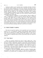
RPC achieves its transparency in an analogous way. When read is actually a
remote procedure (e.g., one that will run on the file server's machine), a different
version of read, called a client stub, is put into the library. Like the original one,
it, too, is called using the calling sequence of Fig. 4-5(b). Also like the original
one, it too, does a call to the local operating system. Only unlike the original one,
it does not ask the operating system to give it data. Instead, it packs the parame-
ters into a message and requests that message to be sent to the server as illustrated
in Fig. 4-6. Following the call to send, the client stub calls receive, blocking it-
self until the reply comes back.
Figure 4-6. Principle of RPC between a client and server program.
When the message arrives at the server, the server's operating system passes
it up to a server stub. A server stub is the server-side equivalent of a client stub:
it is a piece of code that transforms requests coming in over the network into local
procedure calls. Typically the server stub will have called receive and be blocked
waiting for incoming messages. The server stub unpacks the parameters from the
message and then calls the server procedure in the usual way (i.e., as in Fig. 4-5).
From the server's point of view, it is as though it is being called directly by the
SEC. 4.2
REMOTE PROCEDURE CALL
129
client-the parameters and return address are all on the stack where they belong
and nothing seems unusual. The server performs its work and then returns the re-
sult to the caller in the usual way. For example, in the case of read, the server will
fill the buffer, pointed to by the second parameter, with the data. This buffer will
be internal to the server stub.
When the server stub gets control back after the call has completed, it packs
the result (the buffer) in a message and calls send to return it to the client. After
that, the server stub usually does a call to receive again, to wait for the next
incoming request.
When the message gets back to the client machine, the client's operating sys-
tem sees that it is addressed to the client process (or actually the client stub, but
the operating system cannot see the difference). The message is copied to the
waiting buffer and the client process unblocked. The client stub inspects the mes-
sage, unpacks the result, copies it to its caller, and returns in the usual way. When
the caller gets control following the call to read, all it knows is that its data are
available. It has no idea that the work was done remotely instead of by the local
operating system.
This blissful ignorance on the part of the client is the beauty of the whole
scheme. As far as it is concerned, remote services are accessed by making ordi-
nary (i.e., local) procedure calls, not by calling send and receive. All the details
of the message passing are hidden away in the two library procedures, just as the
details of actually making system calls are hidden away in traditional libraries.
To summarize, a remote procedure call occurs in the following steps:
1. The client procedure calls the client stub in the normal way.
2. The client stub builds a message and calls the local operating system.
3. The client's as sends the message to the remote as.
4. The remote as gives the message to the server stub.
5. The server stub unpacks the parameters and calls the server.
6. The server does the work and returns the result to the stub.
7. The server stub packs it in a message and calls its local as.
8. The server's as sends the message to the client's as.
9. The client's as gives the message to the client stub.
10. The stub unpacks the result and returns to the client.
The net effect of all these steps is to convert the local call by the client procedure
to the client stub, to a local call to the server procedure without either client or
server being aware of the intermediate steps or the existence of the network.
130
COMMUNICATION
CHAP. 4
4.2.2 Parameter Passing
The function of the client stub is to take its parameters, pack them into a mes-
sage, and send them to the server stub. While this sounds straightforward, it is not
quite as simple as it at first appears. In this section we will look at some of the
issues concerned with parameter passing in RPC systems.
Passing Value Parameters
Packing parameters into a message is called parameter marshaling. As a
very simple example, consider a remote procedure, add(i,
j),
that takes two integer
parameters
i
and
j
and returns their arithmetic sum as a result. (As a practical
matter, one would not normally make such a simple procedure remote due to the
overhead, but as an example it will do.) The call to add, is shown in the left-hand
portion (in the client process) in Fig. 4-7. The client stub takes its two parameters
and puts them in a message as indicated, It also puts the name or number of the
procedure to be called in the message because the server might support several
different calls, and it has to be told which one is required.
Figure 4-7. The steps involved in a doing a remote computation through RPC.
When the message arrives at the server, the stub examines the message to see
which procedure is needed and then makes the appropriate call. If the server also
supports other remote procedures, the server stub might have a switch statement
in it to select the procedure to be called, depending on the first field of the mes-
sage. The actual call from the stub to the server looks like the original client call,
except that the parameters are variables initialized from the incoming message.
When the server has finished, the server stub gains control again. It takes the
result sent back by the server and packs it into a message. This message is sent
SEC. 4.2
REMOTE PROCEDURE CALL
131
back back to the client stub. which unpacks it to extract the result and returns the
value to the waiting client procedure.
As long as the client and server machines are identical and all the parameters
and results are scalar types. such as integers, characters, and Booleans, this model
works fine. However, in a large distributed system, it is common that multiple ma-
chine types are present. Each machine often has its own representation for num-
bers, characters, and other data items. For example, IRM mainframes use the
EBCDIC character code, whereas IBM personal computers use ASCII. As a con-
sequence, it is not possible to pass a character parameter from an IBM PC client
to an IBM mainframe server using the simple scheme of Fig. 4-7: the server will
interpret the character incorrectly.
Similar problems can occur with the representation of integers (one's comple-
ment versus two's complement) and floating-point numbers. In addition, an even
more annoying problem exists because some machines, such as the Intel Pentium,
number their bytes from right to left, whereas others, such as the Sun SPARC,
number them the other way. The Intel format is called little endian and the
SPARC format is called big endian, after the politicians in Gulliver's Travels
who went to war over which end of an egg to break (Cohen, 1981). As an ex-
ample, consider a procedure with two parameters, an integer and a four-character
string. Each parameter requires one 32-bit word. Fig.4-8(a) shows what the pa-
rameter portion of a message built by a client stub on an Intel Pentium might look
like, The first word contains the integer parameter, 5 in this case, and the second
contains the string "JILL."
Figure 4-8. (a) The original message on the Pentium. (b) The message after re-
ceipt on the SPARe.
(c)
The message after being inverted. The little numbers in
boxes indicate the address of each byte.
Since messages are transferred byte for byte (actually, bit for bit) over the net-
work, the first byte sent is the first byte to arrive. In Fig. 4-8(b) we show what the
message of Fig. 4-8(a) would look like if received by a SPARC, which numbers
its bytes with byte 0 at the left (high-order byte) instead of at the right (low-order
byte) as do all the Intel chips. When the server stub reads the parameters at ad-
dresses 0 and 4, respectively, it will find an integer equal to 83,886,080 (5 x 2
24
)
and a string "JILL".
One obvious, but unfortunately incorrect, approach is to simply invert the
bytes of each word after they are received, leading to Fig. 4-8(c). Now the integer
132
COMMUNICATION
CHAP. 4
is 5 and the string is
"LLIJ".
The problem here is that integers are reversed by the
different byte ordering, but strings are not. Without additional information about
what is a string and what is an integer, there is no way to repair the damage.
Passing Reference Parameters
We now come to a difficult problem: How are pointers, or in general, refer-
ences passed? The answer is: only with the greatest of difficulty, if at all.
Remember that a pointer is meaningful only within the address space of the proc-
ess in which it is being used. Getting back to our read example discussed earlier,
if the second parameter (the address of the buffer) happens to be 1000 on the cli-
ent, one cannot just pass the number 1000 to the server and expect it to work.
Address 1000 on the server might be in the middle of the program text.
One solution is just to forbid pointers and reference parameters in general.
However, these are so important that this solution is highly undesirable. In fact, it
is not necessary either. In the read example, the client stub knows that the second
parameter points to an array of characters. Suppose, for the moment, that it also
knows how big the array is. One strategy then becomes apparent: copy the array
into the message and send it to the server. The server stub can then call the server
with a pointer to this array, even though this pointer has a different numerical val-
ue than the second parameter of read has. Changes the server makes using the
pointer (e.g., storing data into it) directly affect the message buffer inside the
server stub. When the server finishes, the original message can be sent back to the
client stub, which then copies it back to the client. In effect, call-by-reference has
been replaced by copy/restore. Although this is not always identical, it frequently
is good enough.
One optimization makes this mechanism twice as efficient. If the stubs know
whether the buffer is an input parameter or an output parameter to the server, one
of the copies can be eliminated. If the array is input to the server (e.g., in a call to
write) it need not be copied back. If it is output, it need not be sent over in the first
place.
As a final comment, it is worth noting that although we can now handle point-
ers to simple arrays and structures, we still cannot handle the most general case of
a pointer to an arbitrary data structure such as a complex graph. Some systems
attempt to deal with this case by actually passing the pointer to the server stub and
generating special code in the server procedure for using pointers. For example, a
request may be sent back to the client to provide the referenced data.
Parameter Specification and Stub Generation
From what we have explained so far, it is clear that hiding a remote procedure
call requires that the caller and the callee agree on the format of the messages
they exchange, and that they follow the same steps when it comes to, for example,
SEC. 4.2
REMOTE PROCEDURE CALL
133
passing complex data structures. In other words, both sides in an RPC should fol-
low the same protocol or the RPC will not work correctly.
As a simple example, consider the procedure of Fig. 4-9(a). It has three pa-
rameters, a character, a floating-point number, and an array of five integers.
Assuming a word is four bytes, the RPC protocol might prescribe that we should
transmit a character in the rightmost byte of a word (leaving the next 3 bytes
empty), a float as a whole word, and an array asa group of words equal to the
array length, preceded by a word giving the length, as shown in Fig. 4-9(b). Thus
given these rules, the client stub for foobar knows that it must use the format of
Fig. 4-9(b), and the server stub knows that incoming messages for foobar will
have the format of Fig. 4-9(b).
Figure 4-9. (a) A procedure. (b) The corresponding message.
Defining the message format is one aspect of an RPC protocol, but it is not
sufficient. What we also need is the client and the server to agree on the repres-
entation of simple data structures, such as integers, characters, Booleans, etc. For
example, the protocol could prescribe that integers are represented in two's com-
plement, characters in 16-bit Unicode, and floats in the IEEE standard #754 for-
mat, with everything stored in little endian. With this additional information, mes-
sages can be unambiguously interpreted.
With the encoding rules now pinned down to the last bit, the only thing that
remains to be done is that the caller and callee agree on the actual exchange of
messages. For example, it may be decided to use a connection-oriented transport
service such as TCPIIP. An alternative is to use an unreliable datagram service
and let the client and server implement an error control scheme as part of the RPC
protocol. In practice, several variants exist.
Once the RPC protocol has been fully defined, the client and server stubs
need to be implemented. Fortunately, stubs for the same protocol but different
procedures normally differ only in their interface to the applications. An interface
consists of a collection of procedures that can be called by a client, and which are
implemented by a server. An interface is usually available in the same programing
134
COMMUNICA nON
CHAP. 4
language as the one in which the client or server is written (although this is strictly
speaking, not necessary). To simplify matters, interfaces are often specified by
means of an Interface Definition Language (IDL). An interface specified in
such an IDL is then subsequently compiled into a client stub and a server stub,
along with the appropriate compile-time or run-time interfaces.
Practice shows that using an interface definition language considerably sim-
plifies client-server applications based on RPCs. Because it is easy to fully gen-
erate client and server stubs, all RPC-based middleware systems offer an IDL to
support application development. In some cases, using the IDL is even mandatory,
as we shall see in later chapters.
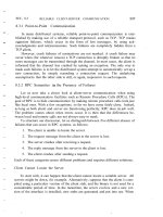
4.2.3 Asynchronous RPC
As in conventional procedure calls, when a client calls a remote procedure,
the client will block until a reply is returned. This strict request-reply behavior is
unnecessary when there is no result to return, and only leads to blocking the client
while it could have proceeded and have done useful work just after requesting the
remote procedure to be called. Examples of where there is often no need to wait
for a reply include: transferring money from one account to another, adding en-
tries into a database, starting remote services, batch processing, and so on.
To support such situations, RPC systems may provide facilities for what are
called asynchronous RPCs, by which a client immediately continues after issu-
ing the RPC request. With asynchronous RPCs, the server immediately sends a
reply back to the client the moment the RPC request is received, after which it
calls the requested procedure. The reply acts as an acknowledgment to the client
that the server is going to process the RPC. The client will continue without
further blocking as soon as it has received the server's acknowledgment. Fig. 4-
1O(b) shows how client and server interact in the case of asynchronous RPCs. For
comparison, Fig. 4-10(a) shows the normal request-reply behavior.
Asynchronous RPCs can also be useful when a reply will be returned but the
client is not prepared to wait for it and do nothing in the meantime. For example,
a client may want to prefetch the network addresses of a set of hosts that it
expects to contact soon. While a naming service is collecting those addresses, the
client may want to do other things. In such cases, it makes sense to organize the
communication between the client and server through two asynchronous RPCs, as
shown in Fig. 4-11. The client first calls the server to hand over a list of host
names that should be looked up, and continues when the server has acknowledged
the receipt of that list. The second call is done by the server, who calls the client
to hand over the addresses it found. Combining two asynchronous RPCs is some-
times also referred to as a deferred synchronous RPC.
It should be noted that variants of asynchronous RPCs exist in which the cli-
ent continues executing immediately after sending the request to the server. In
SEC. 4.2
REMOTE PROCEDURE CALL
135
Figure 4-10. (a) The interaction between client and server in a traditional RPc.
(b) The interaction using asynchronous RPc.
Figure 4-11. A client and server interacting through two asynchronous RPCs.
other words, the client does not wait for an acknowledgment of the server's ac-
ceptance of the request. We refer to such RPCs as one-way RPCs. The problem
with this approach is that when reliability is not guaranteed, the client cannot
know for sure whether or not its request will be processed. We return to these
matters in Chap. 8. Likewise, in the case of deferred synchronous RPC, the client
may poll the server to see whether the results are available yet instead of letting
the server calling back the client.
4.2.4 Example: DCE RPC
Remote procedure calls have been widely adopted as the basis of middleware
and distributed systems in general. In this section, we take a closer look at one
specific RPC system: the Distributed Computing Environment (DeE), which
was developed by the Open Software Foundation (OSF), now called The Open
Group. DCE RPC is not as popular as some other RPC systems, notably Sun RPC.
However, DCE RPC is nevertheless representative of other RPC systems, and its
136
COMMUNICATION
CHAP. 4
specifications have been adopted in Microsoft's base system for distributed com-
puting, DCOM (Eddon and Eddon, ]998). We start with a brief introduction to
DCE, after which we consider the principal workings of DCE RPC. Detailed tech-
nical information on how to develop RPC-based applications can be found in
Stevens (l999).
Introduction to DCE
DCE is a true middleware system in that it is designed to execute as a layer of
abstraction between existing (network) operating systems and distributed applica-
tions. Initially designed for UNIX, it has now been ported to all major operating
systems including VMS and Windows variants, as well as desktop operating sys-
tems. The idea is that the customer can take a collection of existing machines, add
the DCE software, and then be able to run distributed applications, all without dis-
turbing existing (nondistributed) applications. Although most of the DCE package
runs in user space, in some configurations a piece (part of the distributed file sys-
tem) must be added to the kernel. The Open Group itself only sells source code,
which vendors integrate into their systems.
The programming model underlying all of DCE is the client-server model,
which was extensively discussed in the previous chapter. User processes act as
clients to access remote services provided by server processes. Some of these ser-
vices are part of DCE itself, but others belong to the applications and are written
by the applications programmers. All communication between clients and servers
takes place by means of RPCs.
There are a number of services that form part of DCE itself. The distributed
file service is a worldwide file system that provides a transparent. way of ac-
cessing any file in the system in the same way. It can either be built on top of the
hosts' native file systems or used instead of them. The directory service is used
to keep track of the location of all resources in the system. These resources in-
clude machines, printers, servers, data, and much more, and they may be distrib-
uted geographically over the entire world. The directory service allows a process
to ask for a resource and not have to be concerned about where it is, unless the
process cares. The security service allows resources of all kinds to be protected,
so access can be restricted to authorized persons. Finally, the distributed time
service is a service that attempts to keep clocks on the different machines globally
synchronized. As we shall see in later chapters, having some notion of global time
makes it much easier to ensure consistency in a distributed system.
Goals of DCE RPC
The goals of the DCE RPC system are relatively traditional. First and
foremost, the RPC system makes it possible for a client to access a remote service
by simply calling a local procedure. This interface makes it possible for client
SEC. 4.2
REMOTE PROCEDURE CALL
137
(i.e., application) programs to be written in a simple way, familiar to most pro-
grammers. It also makes it easy to have large volumes of existing code run in a
distributed environment with few, if any, changes.
It is up to the RPC system to hide all the details from the clients, and, to some
extent, from the servers as well. To start with, the RPC system can automatically
locate the correct server, and subsequently set up the communication between cli-
ent and server software (generally called binding). It can also handle the mes-
sage transport in both directions, fragmenting and reassembling them as needed
(e.g., if one of the parameters is a large array). Finally, the RPC system can auto-
matically handle data type conversions between the client and the server, even if
they run on different architectures and have a different byte ordering;
As a consequence of the RPC system's ability to hide the details, clients and
servers are highly independent of one another. A client can be written in Java and
a server in C, or vice versa. A client and server can run on different hardware plat-
forms and use different operating systems. A yariety of network protocols and
data representations are also supported, all without any intervention from the cli-
ent or server.
Writing a Client and a Server
The DCE RPC system consists of a number of components, including lan-
guages, libraries, daemons, and utility programs, among others. Together these
make it possible to write clients and servers. In this section we will describe the
pieces and how they fit together. The entire process of writing and using an RPC
client and server is summarized in Fig. 4-12.
In a client-server system, the glue that holds everything together is the inter-
face definition, as specified in the Interface Definition Language, or IDL. It
permits procedure declarations in a form closely resembling function prototypes
in ANSI C. IDL files can also contain type definitions, constant declarations, and
other information needed to correctly marshal parameters and unmarshal results.
Ideally, the interface definition should also contain a formal definition of what the
procedures do, but such a definition is beyond the current state of the art, so the
interface definition just defines the syntax of the calls, not their semantics. At best
the writer can add a few comments describing what the procedures do.
A crucial element in every IDL file is a globally unique identifier for the
specified interface. The client sends this identifier in the first RPC message and
the server verifies that it is correct. In this way, if a client inadvertently tries to
bind to the wrong server, or even to an older version of the right server, the server
will detect the error and the binding will not take place.
Interface definitions and unique identifiers are closely related in DCE. As
illustrated in Fig. 4-12, the first step in writing a client/server application is usual-
ly calling the
uuidgen
program, asking it to generate a prototype IDL file contain-
ing an interface identifier guaranteed never to be used again in any interface
138
COMMUNlCATION
CHAP. 4
Figure 4-12. The steps in writing a client and a server in DeE RPC.
generated anywhere by uuidgen. Uniqueness is ensured by encoding in it the lo-
cation and time of creation. It consists of a 128-bit binary number represented in
the IDL file as an ASCII string in hexadecimal.
The next step is editing the IDL file, filling in the names of the remote proce-
dures and their parameters. It is worth noting that RPC is not totally transpar-
ent-for example, the client and server cannot share global variables-but the
IDL rules make it impossible to express constructs that are not supported.
When the IDL file is complete, the IDL compiler is called to process it. The
output of the IDL compiler consists of three files:
1. A header file (e.g., interface.h, in C terms).
2. The client stub.
3. The server stub.
The header file contains the unique identifier, type definitions, constant defini-
tions, and function prototypes. It should be included (using #include) in both the
client and server code. The client stub contains the actual procedures that the cli-
ent program will call. These procedures are the ones responsible for collecting and
SEC. 4.2
REMOTE PROCEDURE CALL
139
packing the parameters into the outgoing message and then calling the runtime
system to send it. The client stub also handles unpacking the reply and returning
values to the client. The server stub contains the procedures called by the runtime
system on the server machine when an incoming message arrives. These, in tum,
call the actual server procedures that do the work.
The next step is for the application writer to write the client and server code.
Both of these are then compiled, as are the two stub procedures. The resulting cli-
ent code and client stub object files are then linked with the runtime library to pro-
duce the executable binary for the client. Similarly, the server code and server
stub are compiled and linked to produce the server's binary. At runtime, the client
and server are started so that the application is actually executed as well.
Binding a Client to a Server
To allow a client to call a server, it is necessary that the server be registered
and prepared to accept incoming calls. Registration of a server makes it possible
for a client to locate the server and bind to it. Server location is done in two steps:
1. Locate the server's machine.
2. Locate the server (i.e., the correct process) on that machine.
The second step is somewhat subtle. Basically, what it comes down to is that to
communicate with a server, the client needs to know an end point, on the server's
machine to which it can send messages. An end point (also commonly known as a
port) is used by the server's operating system to distinguish incoming messages
for different processes. In DCE, a table of (server, end point)pairs is maintained
on each server machine by a process called the DCE daemon. Before it becomes
available for incoming requests, the server must ask the operating system for an
end point. It then registers this end point with the DCE daemon. The DCE daemon
records this information (including which protocols the server speaks) in the end
point table for future use.
The server also registers with the directory service by providing it the network
address of the server's machine and a name under which the server can be looked
up. Binding a client to a server then proceeds as shown in Fig. 4-13.
Let us assume that the client wants to bind to a video server that is locally
known under the name /local/multimedia/video/movies It passes this name to the
directory server, which returns the network address of the machine running the
video server. The client then goes to the DCE daemon on that machine (which has
a well-known end point), and asks it to look up the end point of the video server in
its end point table. Armed with this information, the RPC can now take place. On
subsequent RPCs this lookup is not needed. DCE also gives clients the ability to
do more sophisticated searches for a suitable server when that is needed. Secure
RPC is also an option where confidentiality or data integrity is crucial.
140
COMMUNICA nON
CHAP. 4
Performing an RPC
The actual RPC is carried out transparently and in the usual way. The client
stub marshals the parameters to the runtime library for transmission using the pro-
tocol chosen at binding time. When a message arrives at the server side, it is
routed to the correct server based on the end point contained in the incoming mes-
sage. The runtime library passes the message to the server stub, which unmarshals
the parameters and calls the server. The reply goes back by the reverse route.
DCE provides several semantic options. The default is at-most-once opera-
tion, in which case no call is ever carried out more than once, even in the face of
system crashes. In practice, what this means is that if a server crashes during, an
RPC and then recovers quickly, the client does not repeat the operation, for fear
that it might already have been carried out once.
Alternatively, it is possible to mark a remote procedure as idempotent (in the
IDL file), in which case it can be repeated multiple times without harm. For ex-
ample, reading a specified block from a file can be tried over and over until it
succeeds. When an idempotent RPC fails due to a server crash. the client can wait
until the server reboots and then try again. Other semantics are also available (but
rarely used), including broadcasting the RPC to all the machines on the local net-
work. We return to RPC semantics in Chap. 8, when discussing RPC in the pres-
ence of failures.
4.3 MESSAGE-ORIENTED COMMUNICATION
Remote procedure calls and remote object invocations contribute to hiding
communication in distributed systems, that is, they enhance access transparency.
Unfortunately, neither mechanism is always appropriate. In particular, when it
cannot be assumed that the receiving side is executing at the time a request is
Figure 4-13. Client-to-server binding in DCE.
SEC. 4.3
MESSAGE-ORIENTED COMMUNICATION
141
issued, alternative communication services are needed. Likewise, the inherent
synchronous nature of RPCs, by which a client is blocked until its request has
been processed, sometimes needs to be replaced by something else.
That something else is messaging. In this section we concentrate on message-
oriented communication in distributed systems by first taking a closer look at
what exactly synchronous behavior is and what its implications are. Then, we dis-
cuss messaging systems that assume that parties are executing at the time of com-
munication. Finally, we will examine message-queuing systems that allow proc-
esses to exchange information, even if the other party is not executing at the time
communication is initiated.
4.3.1 Message-Oriented Transient Communication
Many distributed systems and applications are built directly on top of the sim-
ple message-oriented model offered by the transport layer. To better understand
and appreciate the message-oriented systems as part of middleware solutions, we
first discuss messaging through transport-level sockets.
Berkeley Sockets
Special attention has been paid to standardizing the interface of the transport
layer to allow programmers to make use of its entire suite of (messaging) proto-
cols through a simple set of primitives. Also, standard interfaces make it easier to
port an application to a different machine.
As an example, we briefly discuss the sockets interface as introduced in the
1970s in Berkeley UNIX. Another important interface is XTI, which stands for
the X10pen Transport Interface, formerly called the Transport Layer Interface
(TLI), and developed by AT&T. Sockets and XTI are very similar in their model
of network programming, but differ in their set of primitives.
Conceptually, a socket is a communication end point to which an application
can write data that are to be sent out over the underlying network, and from which
incoming data can be read. A socket forms an abstraction over the actual commu-
nication end point that is used by the local operating system for a specific tran-
sport protocol. In the following text, we concentrate on the socket primitives for
TCP, which are shown in Fig. 4-14.
Servers generally execute the first four primitives, normally in the order
given. When calling the socket primitive, the caller creates a new communication
end point for a specific transport protocol. Internally, creating a communication
end point means that the local operating system reserves resources to accommo-
date sending and receiving messages for the specified protocol.
The bind primitive associates a local address with the newly-created socket.
For example, a server should bind the IP address of its machine together with a
(possibly well-known) port number to a socket. Binding tells the operating system
that the server wants to receive messages only on the specified address and port.
142
COMMUNICATION
CHAP. 4
Figure 4-14. The socket primitives for TCPIIP.
The listen primitive is called only in the case of connection-oriented commu-
nication. It is a nonblocking call that allows the local operating system to reserve
enough buffers for a specified maximum number of connections that the caller is
willing to accept.
A call to accept blocks the caller until a connection request arrives. When a
request arrives, the local operating system creates a new socket with the same pro-
perties as the original one, and returns it to the caller. This approach will allow the
server to, for example, fork off a process that will subsequently handle the actual
communication through the new connection. The server, in the meantime, can go
back and wait for another connection request on the original socket.
Let us now take a look at the client side. Here, too, a socket must first be
created using the socket primitive, but explicitly binding the socket to a local ad-
dress is not necessary, since the operating system can dynamically allocate a port
when the connection is set up. The connect primitive requires that the caller speci-
fies the transport-level address to which a connection request is to be sent. The
client is blocked until a connection has been set up successfully, after which both
sides can start exchanging information through the send and receive primitives.
Finally, closing a connection is symmetric when using sockets, and is established
by having both the client and server call the close primitive. The general pattern
followed by a client and server for connection-oriented communication using
sockets is shown in Fig. 4-15. Details about network programming using sockets
and other interfaces in a
UNIX
environment can be found in Stevens (1998).
The Message-Passing Interface (MPI)
With the advent of high-performance multicomputers, developers have been
looking for message-oriented primitives that would allow them to easily write
highly efficient applications. This means that the primitives should be at a con-
venient level of abstraction (to ease application development), and that their
SEC. 4.3
MESSAGE-ORIENTED COMMUNICATION
143
Figure 4-15. Connection-oriented communication pattern using sockets.
implementation incurs only minimal overhead. Sockets were deemed insufficient
for two reasons. First, they were at the wrong level of abstraction by supporting
only simple send and receive primitives. Second, sockets had been designed to
communicate across networks using general-purpose protocol stacks such as
TCPIIP. They were not considered suitable for the proprietary protocols devel-
oped for high-speed interconnection networks, such as those used in high-perfor-
mance server clusters. Those protocols required an 'interface that could handle
more advanced features, such as different forms of buffering and synchronization.
The result was that most interconnection networks and high-performance
multicomputers were shipped with proprietary communication libraries. These
libraries offered a wealth of high-level and generally efficient communication
primitives. Of course, all libraries were mutually incompatible, so that application
developers now had a portability problem.
The need to be hardware and platform independent eventually led to the
definition of a standard for message passing, simply called the Message-Passing
Interface or MPI. MPI is designed for parallel applications and as such is
tailored to transient communication. It makes direct use of the underlying net-
work Also, it assumes that serious failures such as process crashes or network
partitions are fatal and do not require automatic recovery.
MPI assumes communication takes place within a knowngroup of processes.
Each group is assigned an identifier. Each process within a group is also assigned
a (local) identifier. A (group/D, process/D) pair therefore uniquely identifies the
source or destination of a message, and is used instead of a transport-level ad-
dress. There may be several, possibly overlapping groups of processes involved in
a computation and that are all executing at the same time.
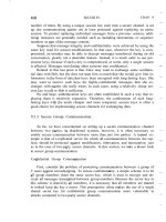
At the core of MPI are messaging primitives to support transient communica-
tion, of which the most intuitive ones are summarized in Fig. 4-16.
Transient asynchronous communication is supported by means of the
MPI_bsend primitive. The sender submits a message for transmission, which is
generally first copied to a local buffer in the MPI runtime system. When the mes-
sage has been copied. the sender continues. The local MPI runtime system will
remove the message from its local buffer and take care of transmission as soon as
a receiver has called a receive primitive.
144
COMMUNICA nON
CHAP. 4
Figure 4-16. Some of the most intuitive message-passing primitives of MPI.
There is also a blocking send operation, called MPLsend, of which the sem-
antics are implementation dependent. The primitive MPLsend may either block
the caller until the specified message has been copied to the MPI runtime system
at the sender's side, or until the receiver has initiated a receive operation. Syn-
chronous communication by which the sender blocks until its request is accepted
for further processing is available through the MPI~ssend primitive. Finally, the
strongest form of synchronous communication is also supported: when a sender
calls MPLsendrecv, it sends a request to the receiver and blocks until the latter
returns a reply. Basically, this primitive corresponds to a normal RPC.
Both MPLsend and MPLssend have variants that avoid copying messages
from user buffers to buffers internal to the local MPI runtime system. These vari-
ants correspond to a form of asynchronous communication. With MPI_isend, a
sender passes a pointer to the message after which the MPI runtime system takes
care of communication. The sender immediately continues. To prevent overwrit-
ing the message before communication completes, MPI offers primitives to check
for completion, or even to block if required. As with MPLsend, whether the mes-
sage has actually been transferred to the receiver or that it has merely been copied
by the local MPI runtime system to an internal buffer is left unspecified.
Likewise, with MPLissend, a sender also passes only a pointer to the
:MPI
runtime system. When the runtime system indicates it has processed the message,
the sender is then guaranteed that the receiver has accepted the message and is
now working on it.
The operation MPLrecv is called to receive a message; it blocks the caller
until a message arrives. There is also an asynchronous variant, called MPLirecv,
by which a receiver indicates that is prepared to accept a message. The receiver
can check whether or not a message has indeed arrived, or block until one does.
The semantics of MPI communication primitives are not always straightfor-
ward, and different primitives can sometimes be interchanged without affecting
SEC. 4.3
MESSAGE-ORIENTED COMMUNICA nON
145
the correctness of a program. The official reason why so many different forms of
communication are supported is that it gives implementers of MPI systems
enough possibilities for optimizing performance. Cynics might say the committee
could not make up its collective mind, so it threw in everything. MPI has been
designed for high-performance parallel applications, which makes it easier to
understand its diversity in different communication primitives.
More on MPI can be found in Gropp et aI. (l998b) The complete reference in
which the over 100 functions in MPI are explained in detail, can be found in Snir
et al. (1998) and Gropp et al. (l998a)
4.3.2 Message-Oriented Persistent Communication
We now come to an important class of message-oriented middle ware services,
generally known as message-queuing systems, or just Message-Oriented Mid-
dleware (MOM). Message-queuing systems provide extensive support for per-
sistent asynchronous communication. The essence of these systems is that they
offer intermediate-term storage capacity for messages, without requiring either the
sender or receiver to be active during message transmission. An important differ-
ence with Berkeley sockets and MPI is that message-queuing systems are typi-
cally targeted to support message transfers that are allowed to take minutes in-
stead of seconds or milliseconds. We first explain a general approach to message-
queuing systems, and conclude this section by comparing them to more traditional
systems, notably the Internet e-mail systems.
Message-Queuing Model
The basic idea behind a message-queuing system is that applications com-
municate by inserting messages in specific queues. These messages are forwarded
over a series of communication servers and are eventually delivered to the desti-
nation, even if it was down when the message was sent. In practice, most commu-
nication servers are directly connected to each other. In other words, a message is
generally transferred directly to a destination server. In principle, each application
has its own private queue to which other applications can send messages. A queue
can be read only by its associated application, but it is also possible for multiple
applications to share a single queue.
An important aspect of message-queuing systems is that a sender is generally
given only the guarantees that its message will eventually be inserted in the re-
cipient's queue. No guarantees are given about when, or even if the message will
actually be read, which is completely determined by the behavior of the recipient.
These semantics permit communication loosely-coupled in time. There is thus
no need for the receiver to be executing when a message is being sent to its queue.
Likewise, there is no need for the sender to be executing at the moment its mes-
sage is picked up by the receiver. The sender and receiver can execute completely
146
COMMUNICATION
CHAP. 4
independently of each other. In fact, once a message has been deposited in a
queue, it will remain there until it is removed, irrespective of whether its sender or
receiver is executing. This gives us four combinations with respect to the execu-
tion mode of the sender and receiver, as shown in Fig. 4-17.
In Fig.4-17(a), both the sender and receiver execute during the entire
transmission of a message. In.Fig. 4-17(b), only the sender is executing, while the
receiver is passive, that is, in a state in which message delivery is not possible.
Nevertheless, the sender can still send messages. The combination of a passive
sender and an executing receiver is shown in Fig. 4-17(c). In this case, the re-
ceiver can read messages that were sent to it, but it is not necessary 'that their re-
spective senders are executing as well. Finally, in Fig. 4-17(d), we see the situa-
tion that the system is storing (and possibly transmitting) messages even while
sender and receiver are passive.
Messages can, in principle, contain any data. The only important aspect from
the perspective of middleware is that messages are properly addressed. In prac-
tice, addressing is done by providing a systemwide unique name of the destination
queue. In some cases, message size may be limited, although it is also possible
that the underlying system takes care of fragmenting and assembling large mes-
sages in a way that is completely transparent to applications. An effect of this ap-
proach is that the basic interface offered to applications can be extremely simple,
as shown in Fig. 4-18.
The put primitive is called by a sender to pass a message to the underlying
system that is to be appended to the specified queue. As we explained. this is a
Figure 4-17. Four combinations for loosely-coupled communications using
queues.
SEC. 4.3
MESSAGE-ORIENTED COMMUNICATION 147
Figure 4-18. Basic interface to a queue in a message-queuing system.
nonblocking call. The get primitive is a blocking call by which an authorized pro-
cess can remove the longest pending message in the specified queue. The process
is blocked only if the queue is empty. Variations on this call allow searching for a
specific message in the queue, for example, using a priority, or a matching pat-
tern. The nonblocking variant is given by the poll primitive. If the queue is empty,
or if a specific message could not be found, the calling process simply continues.
Finally, most queuing systems also allow a process to install a handler as a
callback function, which is automatically invoked whenever a message is put into
the queue. Callbacks can also be used to automatically start a process that will
fetch messages from the queue if no process is currently executing. This approach
is often implemented by means of a daemon on the receiver's side that continu-
ously monitors the queue for incoming messages and handles accordingly.
General Architecture of a Message-Queuing System
Let us now take a closer look at what a general message-queuing system looks
like. One of the first restrictions that we make is that messages can be put only'
into queues that are local to the sender, that is, queues on the same machine, or no
worse than on a machine nearby such as on the same LAN that can be efficiently
reached through an RPC. Such a queue is called the source queue. Likewise,
messages can be read only from local queues. However, a message put into a
queue will contain the specification of a destination queue to which it should be
transferred. It is the responsibility of a message-queuing system to provide queues
to senders and receivers and take care that messages are transferred from their
source to their destination queue.
It is important to realize that the collection of queues is distributed across
multiple machines. Consequently, for a message-queuing system to transfer mes-
sages, it should maintain a mapping of queues to network locations. In practice,
this means that it should maintain a (possibly distributed) database of queue
names to network locations, as shown in Fig. 4-19. Note that such a mapping is
completely analogous to the use of the Domain Name System (DNS) for e-mail in
the Internet. For example, when sending a message to the logical mail address
, the mailing system will query DNS to find the network (i.e., IP)
address of the recipient's mail server to use for the actual message transfer.
148
COMMUNICATION
CHAP. 4
Figure 4-19. The relationship between queue-level addressing and network-
level addressing.
Queues are managed by queue managers. Normally, a queue manager inter-
acts directly with the application that is sending or receiving a message. However,
there are also special queue managers that operate as routers, or relays: they for-
ward incoming messages to other queue managers. In this way, a message-
queuing system may gradually grow into a complete, application-level, overlay
network, on top of an existing computer network. This approach is similar to the
construction of the early MBone over the Internet, in which ordinary user proc-
esses were configured as multicast routers. As it turns out, multicasting through
overlay networks is still important as we will discuss later in this chapter.
Relays can be convenient for a number of reasons. For example, in many mes-
sage-queuing systems, there is no general naming service available that can dy-
namically maintain qneue-to-Iocation mappings. Instead, the topology of the
queuing network is static, and each queue manager needs a copy of the queue-to-
location mapping. It is needless to say that in large-scale queuing systems. this ap-
proach can easily lead to network-management problems.
One solution is to use a few routers that know about the network topology.
When a sender A puts a message for destination B in its local queue, that message
is first transferred to the nearest router, say
Rl,
as shown in Fig. 4-20. At that
point, the router knows what to do with the message and forwards it in the direc-
tion of B. For example, Rl may derive from B's name that the message should be
forwarded to router R2. In this way, only the routers need to be updated when
queues are added or removed. while every other queue manager has to know only
where the nearest router is.
Relays can thus generally help build scalable message-queuing systems. How-
ever, as queuing networks grow, it is clear that the manual configuration of net-
works will rapidly become completely unmanageable. The only solution is to
adopt dynamic routing schemes as is done for computer networks. In that respect,
it is somewhat surprising that such solutions are not yet integrated into some of
the popular message-queuing systems.