autocad 2007 and autocad lt 2007 bible - phần 8 ppsx
Bạn đang xem bản rút gọn của tài liệu. Xem và tải ngay bản đầy đủ của tài liệu tại đây (1.87 MB, 130 trang )
868
Part V ✦ Organizing and Managing Drawings
You can do the following with the DesignCenter:
✦ Browse and insert named drawing components, including blocks (and dynamic blocks),
xrefs, layers, text styles, table styles, dimension styles, linetypes, and layouts. You can
also access custom objects that are created by third-party applications.
✦ Create shortcuts to drawings and locations that you use most often.
✦ Search for drawings and named drawing components.
✦ Open drawings by dragging them into the drawing area.
✦ Create tools for your tool palettes.
✦ View and insert raster image files by dragging them into the drawing area.
Navigating with the DesignCenter
To open the DesignCenter, choose DesignCenter from the Standard toolbar, or choose
Tools➪ Palettes ➪ DesignCenter. As a shortcut, press Ctrl+2. The DesignCenter appears
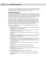
as shown in Figure 26-1. Four tabs provide access to folders, open drawings, history, and DC
Online, where you can find content provided by Autodesk, manufacturers, and other users.
Figure 26-1: The DesignCenter with the Folders tab displayed.
The Folders tab displays a tree view of any location— your hard drive, network, or the
Internet — that you can access. This tree view is very similar to that of Windows Explorer.
Click the plus sign next to a drive or folder to display its contents. Use the vertical scroll bar
to display any location.
Tree view
Content area
Tree view toggle
Preview
Description
Description area
Preview area
36_788864 ch26.qxp 5/22/06 7:42 PM Page 868
869
Chapter 26 ✦ Keeping Control of Your Drawings
A selected drawing displays its named components in the content area on the right side of
the palette. (Use the Views drop-down list to choose the type of display that you want.) You
can also click the plus sign next to a drawing to display these components in the tree view.
Then click a component type, such as blocks, to see a list of the blocks in the drawing, as
shown in Figure 26-1. Click Preview on the DesignCenter toolbar to see a preview in the pre-
view pane of blocks, drawings, and raster images. Click Description to display a description, if
one is saved.
After you narrow your search, you may want to click Tree View Toggle to toggle off the
tree view, thus hiding the navigation pane. By default, the navigation pane displays your
desktop, including the files and folders on your hard drive and network. To narrow your
search, you can click two other tabs from the DesignCenter:
✦ The Open Drawings tab displays currently open drawings.
✦ The History tab displays the most recently opened drawings.
Finding named components and drawings
What do you do if you don’t know the location of the drawing that you want? Suppose you
know the name of the layer, but not the name of the drawing that contains that layer. The
DesignCenter includes a Search feature to help you.
Choose Search from the DesignCenter toolbar to open the Search window, shown in
Figure 26-2. (You can also right-click in the Content area and choose Search.)
Figure 26-2: Use the Search window to locate drawings and
drawing components.
Here’s how to use the Search window:
✦ Click the Look For drop-down list to choose what you’re looking for. You can look for
blocks, dimension styles, drawings, drawings and blocks, hatch pattern files, hatch pat-
terns, layers, layouts, linetypes, table styles, text styles, and xrefs.
36_788864 ch26.qxp 5/22/06 7:42 PM Page 869
870
Part V ✦ Organizing and Managing Drawings
✦ Click the In drop-down list to specify the drive that you want to search. By default, the
Search subfolders check box is checked so that the search looks in all folders and sub-
folders within the drive.
✦ Use the tabbed area to specify the name of the components that you want. The tab’s
name and content change, depending on what you chose in the Look For drop-down
list. For example, if you chose Layers, the tab is called Layers and asks you for the
name of the layer. If you’re looking for drawings, you have three tabs to work with:
• The Drawings tab enables you to look for a drawing by filename (the default),
title, subject, author, or keywords. Choose one of these options in the In the
Field(s) drop-down list. Then type the text that you want to look for in the
Search for the Word(s) text box. You can use the wildcards * (to substitute for
any number of characters), and ? (to substitute for any one character). Specifying
a drawing’s title, subject, and keywords is discussed later in this chapter.
• The Date Modified tab enables you to search by the last date that the file was
saved or modified. You can specify a range of dates, or look in the last x days or
months.
• The Advanced tab enables you to search for text in drawing descriptions,
block names, attribute tags, and attribute values. You can also search here
by drawing size.
✦ When you’ve created your specifications, click Search Now.
See Chapter 18 for information on creating block descriptions when you create a block. The
main reason for creating a block description is to display it in the DesignCenter and use it in
a search on the Advanced tab, as just described.
For more information on searching for drawings, see the section “Finding drawings” later in
this chapter.
Using the Favorites folder
The Favorites folder is a Windows convention that helps you to find files that you use often.
This folder contains shortcuts to actual files. The files remain in their original locations.
Choosing a file from the
Favorites folder has the same effect as choosing the file from its
source location.
You’ll find an
Autodesk subfolder within the Favorites folder, where you can store short-
cuts to drawings and other files that you use often. You can then easily open the
Favorites
folder and find these files. Favorites is one possible place to keep drawings that contain
block libraries.
To add a shortcut to
Favorites, right-click the drawing (or other file) in the DesignCenter
and choose Add to Favorites.
If you right-click in the Content pane and choose Add to Favorites, the DesignCenter adds a
shortcut to the entire content of the folder. This is great for adding all of the items in a folder
at once, but if you do it inadvertently, you could end up with more files than you want in
Favorites. To add one item, remember to select it first.
Caution
Cross-
Reference
36_788864 ch26.qxp 5/22/06 7:42 PM Page 870
871
Chapter 26 ✦ Keeping Control of Your Drawings
To access the drawings in Favorites, click Favorites on the DesignCenter toolbar.
You can also right-click the content pane and choose Favorites. The
Favorites folder
appears in the content pane.
To move, copy, or delete shortcuts from
Favorites, right-click the content pane and choose
Organize Favorites.
Accessing named drawing components
As soon as you have the item that you need in the Content area, you need to insert it into
your drawing. If you used the Search window to locate a file, then you can also insert directly
from the results that you find. You can either drag the item onto the drawing area or right-click
it and choose an option. Sometimes these two methods provide slightly different results.
In this section, I explain how to insert drawing components into your drawing.
Inserting drawings
You can insert an entire drawing into your drawing. Choose the drawing’s folder in the naviga-
tion pane so that the drawing appears in the content area. Drag the drawing’s icon onto the
drawing area. The command line prompts you for an insertion point, scale, and rotation
angle, using the -INSERT command (the command-line version of the INSERT command).
If you right-click the drawing, you can choose to insert the drawing as a block, or attach it as
an xref.
Opening drawings
You can open a drawing using the DesignCenter. Display the drawing in the content pane,
right-click it, and choose Open in Application Window. The drawing opens, keeping your
current drawing open as well.
Inserting blocks
In Chapter 5, I explain that you can use the Units dialog box (choose Format ➪ Units) to set
a unit, such as inches, for automatically scaling drawings when they’re inserted from the
DesignCenter.
You can insert blocks in two ways:
✦ If you drag the block’s icon onto the drawing area, the drawing uses Autoscaling, which
compares the current drawing’s units with those of the block, and scales the block
appropriately, using the value set in the Units dialog box. The block takes on default
scale and rotation.
✦ If you double-click the block’s icon or right-click it and choose Insert Block, the Insert
dialog box opens, where you can specify the insertion point, scale, and rotation.
Inserting raster images
A raster image is a bitmap graphic file. You can insert raster images directly into your draw-
ing (in AutoCAD only).
See Chapter 27 for more information on raster images, including determining which type of
files you can import, attaching images, clipping images, and controlling how they’re displayed.
Cross-
Reference
36_788864 ch26.qxp 5/22/06 7:42 PM Page 871
872
Part V ✦ Organizing and Managing Drawings
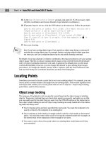
To attach a raster image, drag its icon onto the drawing area. The command line prompts you
for an insertion point, scale, and rotation angle.
Knowing the appropriate scale of an image before inserting it is often difficult. When you
move the cursor at the Specify scale factor or [Unit] <1>: prompt, you can see a
bounding box that will help you visualize the resulting size of the image.
Attaching an xref
To attach or overlay an xref, right-click its icon and choose Attach as Xref to open the
External Reference dialog box. Choose either Attachment or Overlay in the Reference Type
section. Specify an insertion point, scale, and rotation (or choose to specify them on-screen),
and click OK.
If you drag the xref onto the drawing area, you see prompts on the command line that are
similar to those of the INSERT command.
Inserting layers and styles
To insert a layer, layout, linetype, text style, table style, or dimension style into a drawing,
drag its icon onto the drawing area. Of course, these items don’t appear in your drawing area,
but they’re added to the drawing’s database.
You can drag multiple items at one time. To select a contiguous group, click the first item,
press and hold Shift, and click the last item. To select individual multiple items, click the first
item, press and hold Ctrl, and click any other item that you want to insert. You can also
double-click an item to insert it.
The insertion process does not check for duplicate layer names. If you try to insert a layer with
the same name as a layer in your current drawing, you see a message: Layer(s) added.
Duplicate definitions will be ignored. You should check for duplicate layer names
before trying to insert layers from the DesignCenter.
Inserting content from DC Online
The DC Online tab provides access to online resources, including standard parts and man-
ufacturers’ information. Figure 26-3 shows some of the DC Online content. To insert any
content, select it and drag it into your drawing. Follow the prompts for insertion point,
scale, and rotation.
Controlling the DesignCenter display
The DesignCenter provides several controls that help you manage its display.
A great feature of the DesignCenter is the preview pane. Click Preview and select the
item in the content pane. You may or may not see a preview of a block. (A preview icon
is created automatically when you use the Block Definition dialog box to create a block.)
Usually, you’ll see a preview of drawings and raster images. No previews exist for layers, line-
types, text styles, and so on.
Caution
Tip
36_788864 ch26.qxp 5/22/06 7:42 PM Page 872
873
Chapter 26 ✦ Keeping Control of Your Drawings
Figure 26-3: The DC Online tab of the DesignCenter offers a large
selection of content that you can drag into your drawing.
If you have old blocks that don’t have preview icons, use the BLOCKICON command and
press Enter at the first prompt to automatically create preview icons of all the blocks in a
drawing.
If you saved a description with a block, select the block in the content pane and click
Description on the DesignCenter toolbar to see the description.
To set the view, choose Views from the DesignCenter toolbar. The drop-down arrow
lets you choose from four types of displays: large icons, small icons, list, and details.
If you make changes in the structure of a folder while the DesignCenter is open— for example,
by deleting a drawing using Windows Explorer — right-click the navigation or content pane
and choose Refresh. The DesignCenter re-reads the data and refreshes the list.
To dock the DesignCenter, right-click the title bar and choose Allow Docking. Then choose
Anchor Left or Anchor Right to dock it to the left or right of your drawing window. To collapse
the DesignCenter down to its title bar when you’re not using it, right-click the title bar and
choose Auto-Hide; whenever you move the mouse cursor off the DesignCenter, it collapses.
Just move the cursor back onto the title bar to expand it again. You can anchor the
DesignCenter at the same side as other palettes; its title bar becomes shorter to fit. When
you expand it, it rolls down to its full length. To avoid unwanted docking, either uncheck
Allow Docking on its title bar or press Ctrl as you drag. These instructions apply to all palettes
in AutoCAD and AutoCAD LT.
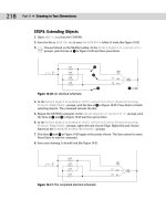
The drawings used in the following exercise on using the DesignCenter, ab26-a.dwg and
ab26-b.dwg, are in the Drawings folder on the CD-ROM.
On the
CD-ROM
Tip
Tip
36_788864 ch26.qxp 5/22/06 7:42 PM Page 873
874
Part V ✦ Organizing and Managing Drawings
STEPS: Using the DesignCenter
1. Open ab26-a-dwg from the CD-ROM.
2. Save the file as
ab26-01.dwg in your AutoCAD Bible folder. This drawing needs an
updated set of layers and a title block. It is shown in Figure 26-4.
Figure 26-4: This drawing needs updated layers and
a title block.
Thanks to Vladimir Sevastyanov of Ukraine for this drawing of
a gyrating swivel that feeds oil to an uncoiling machine used
in the cold rolling of metal.
3. Choose Tools➪ Palettes ➪ DesignCenter. If the navigation pane is not displayed, click
the Folders tab and then click Tree View Toggle on the DesignCenter toolbar.
4. In the navigation pane, locate
ab26-b.dwg on the CD-ROM. Click its plus sign.
5. Choose Blocks. The
ansi_d block appears in the content pane. Double-click ansi_d.
Uncheck all Specify Onscreen check boxes and click OK.
6. Do a Zoom Extents.
7. In the navigation pane, click Layers for
ab26-b.dwg.
8. In the content pane, click the first layer, press and hold Shift, and click the last layer to
select all of the layers. Drag them onto the drawing area to import the layers.
9. Save your drawing.
Accessing Drawing Content with Tool Palettes
The Tool Palettes window is a tabbed palette that can contain drawings, blocks, hatches,
images, gradients (AutoCAD only), drawing objects, xrefs, tables, and commands. By default,
the Tool Palettes window contains over two dozen tabs in AutoCAD and seven tabs in
36_788864 ch26.qxp 5/22/06 7:42 PM Page 874
875
Chapter 26 ✦ Keeping Control of Your Drawings
AutoCAD LT with sample content and commands. Each tab is considered a separate tool
palette within the main Tool Palettes window. Figure 26-5 shows the default Tool Palettes
window with the Draw tab on top. To open the Tool Palettes window, choose Tool Palettes
Window on the Standard toolbar, choose Tools ➪ Palettes ➪ Tool Palettes, or press Ctrl+3.
Figure 26-5: The standard Tool Palettes window has many
tabs, each with a different category of commands or
insertable content.
The tool palettes are meant to be customized with your own content. You can easily create
new tabs with your own blocks and other types of content, objects, or commands. After you
create the tab, you can drag the items into your drawing. A tool is any item on a tool palette,
and is represented by an icon.
Because there are so many tabs, several of the tabs overlap together at the bottom so that
you can’t see their titles. When you click these tabs, a menu pops up, listing the names of all
of the tabs. Click the tab you want from the menu to display that tab. In AutoCAD 2007,
materials used for rendering are on several new palettes; other new palettes contain visual
style, light, and camera tools.
Creating a new tool palette
When you create a new tool palette, you add a tab to the Tool Palettes window. To create
an empty tool palette, right-click in the Tool Palettes window and choose New Tool Palette.
A label appears so that you can name the tool palette. Type the name and press Enter.
When you have a new tool palette, you’re ready to add tools to the palette, as I explain in
the following sections.
You can also create a new, empty tool palette by using the Customize dialog box. See the
“Customizing Tool Palettes” section in Chapter 29 for details.
Cross-
Reference
Note
36_788864 ch26.qxp 5/22/06 7:42 PM Page 875
876
Part V ✦ Organizing and Managing Drawings
You can add descriptive text and separator bars to any tool palette. For example, you can
include instructions that explain a tool and organize commands into groups using separator
bars. To add text or separators, right-click any tool palette and choose Add Text or Add
Separator from the shortcut menu.
Adding content tools
The easiest way to create a new tool palette is from the DesignCenter, discussed in the previ-
ous section of this chapter. When you use this method, you simultaneously create not only
the tool palette, but also its contents. To create a new tool palette, follow these steps:
1. Open the DesignCenter.
2. In the tree view or content area, navigate to a folder, drawing file, block icon, graphic
image file, or hatch icon.
3. Right-click the item and choose Create Tool Palette.
• If you select a folder or drawing, choose Create Tool Palette of Blocks.
• If you select a hatch file (
*.pat), choose Create Tool Palette of Hatch Patterns.
After a few seconds, the new tool palette tab displays, showing each drawing, block, or
hatch on the tab:
• If you chose a folder, the tab includes all drawing files in the folder.
• If you chose a drawing file, the tab includes all blocks in the drawing.
• If you chose a block icon, the tab includes the block.
• If you chose a hatch pattern file, the tab includes all hatch patterns in the
.pat file.
(See Chapter 31 for more information about creating hatch patterns in
.pat files.)
• If you chose a hatch icon, the tab includes the hatch pattern.
Another way to add content tools is to drag content directly from an open drawing. This
method is the only way to add gradients to a tool palette, but it works with any other type of
content as well. Just select the object, then click and drag it onto the tool palette. The tool
palette assigns a name, but you can change it to anything you want. Right-click the tool and
choose Rename. Type the new name and press Enter.
When you drag content from your drawing, you’re creating a tool by example. The properties
of the tool match those of the object in your drawing. For example, if you drag a hatch on
layer
object onto a tool and then use that tool to hatch a closed object in your drawing, you
create a hatch on layer
object.
Adding command tools
You can add commands to tool palettes. You choose your methods, depending on the amount
of customization that you want and how you want to organize your commands. You can add
commands by dragging objects from a drawing, buttons from a toolbar, or commands from
the Commands List pane in the Customize User Interface editor.
36_788864 ch26.qxp 5/22/06 7:42 PM Page 876
877
Chapter 26 ✦ Keeping Control of Your Drawings
Dragging objects from your drawing
You can drag drawing objects, such as circles, text, and so on onto a tool palette. AutoCAD
creates a command tool that draws an object with the same properties as the original object.
For example, if you regularly need to enter text on the Annotation layer using the Annotation
text style, select some existing text with those properties, and drag it onto a tool palette. The
tool is now called simply MText. Right-click, choose Rename, and enter Annotation or another
meaningful name. This command tool contains the properties of the object that you used.
When you click the selected object to start dragging it, don’t click it on the grip handles.
When you click, you’ll see the drag-and-drop arrow cursor, and then you can drag the object
to the tool palette. To drag a table, you must drag-and-drop with the right mouse button;
otherwise, you simply select one of the table cells.
When you create certain types of command tools, the tool palette recognizes the command
as one of a group of commands, and creates an entire group, or flyout, of command tools that
all use the same properties as the original. This technique works with dimensions and com-
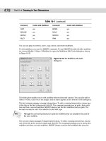
mon drawing geometry objects, such as lines and circles. Figure 26-6 shows an example of
such a flyout on a custom tool palette. Note, however, that the tool palettes include these
flyouts by default.
Figure 26-6: Creating one dimension tool automatically creates a
flyout of all of the dimension tools.
Dragging buttons from a toolbar
You can drag buttons from a toolbar onto a tool palette. These can be the standard toolbar
buttons or custom buttons that you’ve created. To transfer toolbar buttons to a tool palette,
follow these steps:
1. Display the toolbar that you want to use.
2. Choose Tools➪ Customize ➪ Tool Palettes or right-click in the Tool Palettes window
and choose Customize Palettes. The Customize dialog box opens.
3. One by one, drag the buttons that you want onto the tool palette. (The Customize dia-
log box doesn’t seem to have any function here, but you can’t drag buttons off of a tool-
bar without it.)
Note
36_788864 ch26.qxp 5/22/06 7:42 PM Page 877
878
Part V ✦ Organizing and Managing Drawings
In AutoCAD 2007, you can add commands from the Command List pane of the Customize
User Interface dialog box. Right-click the Tool Palettes window and choose Customize
Commands. Then drag any command from the dialog box to any Tool Palette tab.
Copying a tool
You can copy an existing tool to create a new tool, whether a content tool or a command tool.
You can then change the tool properties. You can use this technique to create related, but
slightly different, tools. For example, you could include a hatch on two different layers.
You could also include variations of a dynamic block.
To copy a tool, right-click the tool and choose Copy from the shortcut menu. Then right-click
again and choose Paste. The next section explains how to change tool properties.
Setting tool properties
Each tool on a tool palette has properties that you can set. The available properties vary
slightly, depending on the type of tool. The properties specify how that tool is inserted into a
drawing. Tools inherit their properties from the object that you dragged onto the tool palette.
However, you can change the properties. To set the properties of a tool, right-click it and
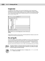
choose Properties to open the Tool Properties dialog box. Figure 26-7 shows the Tool
Properties dialog box for a hatch tool.
Figure 26-7: The Tool Properties dialog box for a
hatch pattern.
The middle section of the dialog box contains Insert, Attach, or Pattern properties, and the
bottom of the dialog box displays General properties.
New
Feature
36_788864 ch26.qxp 5/22/06 7:42 PM Page 878
879
Chapter 26 ✦ Keeping Control of Your Drawings
To specify any property, click the right column for that property. Either type a new value or
choose from the drop-down list. After you’re done, click OK to close the Tool Properties dia-
log box.
You can select multiple tools and change their common properties at one time. To select
multiple tools, press Ctrl and click the tools that you want to change.
Adjusting the scale of inserted content
The tools that you create by dragging content from a drawing take their properties from that
object, and so they may contain an inherent scale. For example, your hatches, blocks, and
xrefs have a certain size. If you need to adjust a scale, you can do so, based on one of the
following:
✦ Your overall dimension scale: You set the dimension scale on the Fit tab of the Modify
Dimension Style dialog box. The value is stored in the DIMSCALE system variable.
✦ Your plot scale: You set the plot scale in the Plot dialog box.
To set the scale of a hatch, block, or xref tool, right-click the tool and choose Properties.
Click the Auxiliary Scale item. Then click the down arrow that appears at the right, and
choose either Dimscale or Plot Scale. Click OK. From now on, the block or xref comes into
your drawing at the scale that you’ve set in your drawing.
Moving, deleting, and renaming tools and tool palettes
You can change the order of both tool palettes (tabs) in the Tool Palettes window and of tools
on a palette.
✦ To move a tool on a palette, drag the tool. A horizontal cursor appears to show you
where the tool will go.
✦ To move a palette, right-click the tab itself and choose Move Up or Move Down.
You can also move or copy a tool (drawing, block, or hatch) from one tool palette to another.
Follow these steps:
1. Display the tool palette (tab) that contains the item that you want to move.
2. Right-click the item and choose Cut (to move it) or Copy (to copy it).
3. Display the tool palette (tab) where you want to place the item.
4. Right-click any blank area on the tab and choose Paste.
You can use this method to consolidate tabs or reorganize the tools on a tab.
To delete a tool palette, right-click the palette and choose Delete Tool Palette. A warning mes-
sage is displayed, explaining that you cannot recover the deleted tool palette unless you
export it to a file. To delete a tool on a tool palette, right-click the tool and choose Delete
Tool. Here, too, you need to confirm the deletion when a warning message appears.
To export a tool palette, you save it to a file. You can then share tool palettes with others.
You import and export tool palettes on the Tool Palettes tab in the Customize dialog box.
See “Customizing Tool Palettes” in Chapter 29 for details.
Tip
36_788864 ch26.qxp 5/22/06 7:42 PM Page 879
880
Part V ✦ Organizing and Managing Drawings
To rename a tool palette, right-click the palette and choose Rename Tool Palette. To rename a
tool, right-click the tool and choose Rename. In both situations, type a new name and press
Enter.
Updating tools
If the source of a tool changes, its icon does not automatically change to match. In this situa-
tion, the icon will not accurately represent its tool. To update an icon, use one of the following
methods:
✦ Right-click the tool and choose Properties. Click the Source File (or Pattern Name)
item, then use the Ellipsis button to choose any other file, block, or hatch pattern,
and then immediately choose the correct item again. This technique updates the
icon for the tool.
✦ Delete the tool and reinsert it.
If you change a block or dynamic block, you can update its image. Right-click the image and
choose Update Tool Image from the shortcut menu.
If you move the source file for a tool, you need to update the tool with the new location:
1. Right-click the tool and choose Properties.
2. In the Tool Properties dialog box, use the Ellipsis button to choose the file again.
3. Click OK.
Setting tool palette options
To work most comfortably with the Tool Palettes window, you can adjust its display options.
Right-click any empty area on the tool palette (except the tab itself) and choose from the fol-
lowing options:
✦ Allow Docking: Enables you to dock the tool palette on the left or right side of the
drawing area.
✦ Anchor Left or Anchor Right: Docks the tool palette on the left or right.
✦ Auto-Hide: Collapses the tool palette to just its title bar when the mouse cursor is off
the Tool Palettes window. Pass the mouse cursor back over the title bar to expand the
tool palette again. You can store the collapsed tool palette outside the application win-
dow (if it isn’t fully maximized).
✦ Transparency: Opens the Transparency dialog box. When the tool palette is transpar-
ent, you can see the drawing through it. You can specify the amount of transparency or
turn it off. Then click OK.
Transparency is available only when hardware acceleration is off (which it is by default).
Hardware acceleration is governed by your computer’s video card and helps to speed up the
display. If you want to use the transparency feature, you can use software acceleration
instead (and see if it affects your display speed). Choose Tools➪ Options and click the
System tab. In the 3D Performance section, click Performance Settings. In the Hardware and
Performance Tuning section, click Manual Tune. In the Hardware Settings section, deselect
the Enable Hardware Acceleration check box. Click OK three times to close all of the dialog
boxes. Transparency is available only when the palette is not docked. This feature is not avail-
able for AutoCAD LT.
Note
36_788864 ch26.qxp 5/22/06 7:42 PM Page 880
881
Chapter 26 ✦ Keeping Control of Your Drawings
✦ View Options: Opens the View Options dialog box. You can change the size and layout
of the tool icons on a tool palette. Use the slider to change the size of the icons. Choose
from the following display styles:
• Icon only: You see the icon displaying the drawing, block, or hatch, but no text.
• Icon with text: Text is displayed beneath each icon, and the icons are arranged in
columns. This option displays much more on a tab than the list view.
* List view: You see one column of icons, with the text to the right of each icon.
✦ You can choose to apply the changes to the current tool palette or to all tool palettes.
Click OK when you’re done.
Organizing tool palettes
You may have one set of tool palettes for architectural work and another for mechanical
work. For whatever reason, you may want to display one set of tool palettes at one time and
another set at another time. For this purpose, you organize tool palettes into groups. I explain
how to create these groups in Chapter 29.
To display the various groups, right-click the title bar of the tool palette and choose the
group that you want. Using groups helps to avoid clicking through too many tool palettes.
After all, the point is instant access. However, you can always display all of the palettes by
right-clicking and choosing All Palettes.
Using a tool palette
Inserting a tool from a tool palette is as simple as dragging the tool onto the drawing area.
The tool is inserted using the properties specified in the Tool Properties dialog box (dis-
cussed previously in this section).
Tools know how to behave. Drag a gradient or hatch into an enclosed area and it automati-
cally fills the area. Drag an xref onto a drawing and you get a prompt, at the command line,
for the insertion point. Tools automatically use their properties so that you get a circle on its
proper layer or a hatch with the proper scale.
If you want the flexibility to insert a block or hatch with more than one setting, you can insert
another copy of the item onto a tool palette. For example, you can place two copies of a
hatch pattern on a tool palette and set their properties to different spacing. You would then
rename the tools to make the differences clear (for example,
lightning1 and lightning 2).
You can also copy a tool and then modify it, as I explain in the section “Copying a tool” earlier
in this chapter.
The drawings used in the following exercise on creating and using a tool palette,
ab26-c.dwg and ab26-d.dwg, are in the Drawings folder on the CD-ROM.
STEPS: Creating and Using a Tool Palette
1. Open ab26-c-dwg from the CD-ROM.
On the
CD-ROM
36_788864 ch26.qxp 5/22/06 7:42 PM Page 881
882
Part V ✦ Organizing and Managing Drawings
2. Save the file as ab26-02.dwg in your AutoCAD Bible folder. This drawing, shown in Fig-
ure 26-8, needs some blocks and a hatch pattern inserted. You’ll also add a dimension.
Figure 26-8: This back porch needs some columns (which are
blocks), some hatching, and a dimension.
3. Choose Tools➪ Palettes ➪ Tool Palettes.
4. Choose Tools➪ Palettes ➪ DesignCenter. In the DesignCenter’s Folder List, navigate to
the
Drawings folder of your CD-ROM and click the plus sign to the left of ab26-d.dwg.
Click the Blocks item to display the two blocks (
post and post-structural) in the
content area on the right side of the DesignCenter.
5. To display the Samples tool palettes group, right-click the Tool Palettes window title
bar and choose Samples.
6. Right-click any empty area of the tool palette, and choose New Palette. A label appears.
Type 2d arch and press Enter. You now have a new tool palette named
2d arch.
If the tool palette is collapsed when the mouse cursor is not over it, right-click its title bar and
choose Auto-Hide to uncheck this item.
7. From the content area of the DesignCenter, drag each of the blocks to the new tool
palette. An icon appears on the tool palette for each block.
8. In the Folder List of the DesignCenter, navigate to
acad.pat or acadlt.pat, which con-
tains hatch patterns. Click
acad.pat or acadlt.pat to display the hatch patterns in
the content area.
To find the location of acad.pat or acadlt.pat, choose Tools ➪ Options and click the
Files tab. Double-click the first item, Support File Search Path, to display the location of the
support files.
9. Drag User Defined, one of the hatch patterns, to the tool palette. (This hatch pattern is
equivalent to choosing User Defined as the Hatch Type in the Hatch and Gradient dia-
log box. See “Creating Hatches” in Chapter 16 for details.) The tool palette now has
three items on it. Close or Auto-Hide the DesignCenter.
Note
Note
5
4
1 2 3
36_788864 ch26.qxp 5/22/06 7:42 PM Page 882
883
Chapter 26 ✦ Keeping Control of Your Drawings
10. Right-click the User Defined hatch icon and choose Properties to open the Tool Properties
dialog box. You want to specify settings so that this hatch pattern will look like scored
concrete for the porch floor.
11. In the Tool Properties dialog box, make the following changes and then click OK:
• For the Angle, type 45.
• For the Spacing, type 2' (or 24).
• Click the Double item at the bottom of the Pattern section and then click the
arrow at the right side of the row. Choose Yes from the drop-down list.
• Click the Layer item in the General section and choose FLOOR from the drop-
down list. (You may have to drag the bottom edge of the dialog box down to
see the layer item.)
12. Right-click the hatch tool and choose Rename. Type porch tile and press Enter.
13. Drag the User Defined hatch icon to
1 in Figure 26-8. Then do the same for 2 and 3.
These areas are hatched, as shown in Figure 26-9.
14. Choose the Command Tools tab and click the small arrow to the right on the Linear
Dimension tool to see the flyout. (If you don’t see the Command Tools tab, click the
overlapping tabs at the bottom of the palette window and choose Command Tools from
the list of tabs.) To place a linear dimension, click the main linear dimension icon.
Follow the prompts:
Specify first extension line origin or <select object>: Pick the
upper-left corner of the porch.
Specify second extension line origin: Pick the upper-right corner of
the porch.
Specify dimension line location or
[Mtext/Text/Angle/Horizontal/Vertical/Rotated]: Pick any location for
the dimension line above the steps.
15. Choose Zoom Window from the Zoom flyout on the Standard toolbar (or choose View ➪
Zoom ➪ Window), and zoom into the central area of the drawing so that you can still
see the double doors at the bottom and the steps at the top.
16. Switch back to the
2d arch tab and click the Post icon. At the Specify insertion
point: prompt, pick the intersection at 4 in Figure 26-8. Click the Post-Structural icon.
At the prompt, pick the upper-right corner of the post block, as shown in Figure 26-9.
17. Click the Post icon. At the prompt, pick
5 in Figure 26-8. Use the same technique to
place the Post-Structural icon at the upper-right corner of the post block. (The posts
would then need to be spaced and mirrored to the other side of the porch, but these
tasks are not necessary for this exercise.)
18. Right-click the tool palette’s title bar. If Allow Docking is checked, click Allow Docking
to uncheck this item. If Auto-Hide is not checked, click Auto-Hide to enable this feature.
Move the mouse off the tool palette. It collapses to its title bar. Move the tool palette to
the right side of your screen.
36_788864 ch26.qxp 5/22/06 7:42 PM Page 883
884
Part V ✦ Organizing and Managing Drawings
19. If you’re working on someone else’s computer, you should delete the tool palette. Move
the cursor over the palette to display it. Right-click any blank area and choose Delete
Palette. Click OK to confirm the deletion.
20. Save your drawing. It should look like Figure 26-9.
Figure 26-9: The drawing now has hatches and blocks
inserted from the tool palette. It also has a new dimension.
Setting Standards for Drawings
One person rarely has complete control over a drawing. You may xref in other drawings, or
others may xref in your drawings. Several people may work on one drawing. You may send a
drawing to a client who may work on it as well. More and more, working on a drawing is
becoming a collaborative effort — and it can get out of control.
One way to maintain control is to set standards for drawings, and to issue those standards so
that everyone involved has access to them. If you don’t have agreed-upon standards, you not
only waste time changing layers, text styles, and so on, but your drawings become very com-
plicated. You should set standards for the following:
✦ Drawing names and property summaries
✦ Blocks, including names, layers, and insertion points
✦ Layers, including uses, names, colors, linetypes, and lineweights
✦ Text styles, including uses, names, and properties
✦ Table styles
✦ Dimension styles and tolerances, if any
✦ Multiline styles
✦ Units settings
✦ Plot styles
✦ Layouts
In some cases, your standards are set by outside conventions. For example, the American
Institute of Architects (AIA) and the Construction Standards Institute (CSI) publish layering
standards for members.
36_788864 ch26.qxp 5/22/06 7:42 PM Page 884
886
Part V ✦ Organizing and Managing Drawings
Associating a standards file with a drawing
As soon as you have your standards file, you associate it with a drawing or template that you
want to check, using the STANDARDS command.
If you use a template to start new drawings, open the template and associate the standards
file with your template. Then, every drawing that you start based on the template is associ-
ated with the standards file.
To associate a standards file with the current drawing, follow these steps:
1. On the CAD Standards toolbar, click Configure Standards. (You can also choose
Tools➪ CAD Standards ➪ Configure or type standards ↵.)
2. On the Standards tab of the Configure Standards dialog box, shown in Figure 26-10,
click the + button.
Figure 26-10: Use the Configure Standards dialog box to associate
a standards file with a drawing.
3. In the Select Standards File dialog box, choose the standards file that you want to use
and click Open. You can associate more than one standards file with the drawing; con-
tinue to click the + button and choose more standards files.
4. Click the Plug-ins tab and click any standards that you don’t want to check. All four
standards types— Dimension Styles, Layers, Linetypes, and Text Styles — are initially
checked. (The choices that you make persist for future standards checks until you
change them.)
5. Click OK to close the Configure Standards dialog box and return to your drawing.
Checking a drawing against standards
To check a drawing against its associated standards file, choose Check Standards from
the CAD Standards toolbar to start the CHECKSTANDARDS command (or choose Tools➪
CAD Standards➪ Check) and open the Check Standards dialog box, shown in Figure 26-11.
If you just finished associating a standards file with a drawing, you can click Check Standards
in the Configure Standards dialog box.
Note
Tip
36_788864 ch26.qxp 5/22/06 7:42 PM Page 886
887
Chapter 26 ✦ Keeping Control of Your Drawings
Figure 26-11: The Check Standards dialog box
guides you through the process of checking a
drawing against a standards file.
The Check Standards dialog box lists all of the problems — items in the drawing that don’t
match the standards file— that it finds, one by one. Here’s the procedure for using this
dialog box:
1. You see the first problem in the Problem section of the dialog box.
2. Use the Replace With section to choose a replacement for the nonstandard item.
This section contains all eligible replacements according to the standards file.
3. Look at the Preview of Changes section to see how the replacement will affect your
drawing.
4. To make the replacement and standardize your drawing, click the Fix
button.
To ignore the problem and go on to the next one, click the Next button.
AutoCAD continues to display problems that you can fix or ignore. After you’re done,
you see the
Checking is complete message in the Problem area, along with a short
report explaining how all of the problems were handled, as shown in Figure 26-12. You
can click the Next button again to recheck the drawing.
5. Click Close to return to your drawing.
Figure 26-12: The completed standards
check report.
36_788864 ch26.qxp 5/22/06 7:42 PM Page 887
888
Part V ✦ Organizing and Managing Drawings
Checking Standards for Multiple Drawings
What do you do if you want to check standards for hundreds of drawings at once? For this sce-
nario, AutoCAD has created Batch Standards Checking, shown here. Here’s how to use the Batch
Standards Checker:
1. From the Windows taskbar, choose Start ➪ [All] Programs➪ Autodesk ➪ AutoCAD 2007 ➪
Batch Standards Checker. The Batch Standards Checker, shown in the following figure,
appears.
2. On the Drawings tab, click the + button and select the drawings that you want to include.
Click Open. After you click Open, you can click the + button again and add drawings from
a different folder. Use the Delete button to delete drawings and the Move Up and Move
Down buttons to change the order of the drawings. If you also want to check external ref-
erences, check the Check External References of Listed Drawings check box. Note that
you can’t check password-protected drawings.
3. On the Standards tab, choose to check each drawing against its associated standards file
if you have associated standards files for all of your drawings. Otherwise, choose to check
the drawings against the standards file(s) that you select. To select a standards file, click
the + button, choose a standards file (
.dws), and click Open.
4. On the Plug-ins tab, choose the standards that you want to check. This tab is the same as
the Plug-ins tab of the Configure Standards dialog box, discussed earlier in this section.
5. Click Save on the Batch Standards Checker toolbar. In the Batch Standards Checker— File
Save dialog box, save the standards check file. A standards check file (
.chx) contains
information about which drawings and standards files you’re using for the batch standards
check. AutoCAD gives the file a default name, but you can change the name if you want.
36_788864 ch26.qxp 5/22/06 7:42 PM Page 888
889
Chapter 26 ✦ Keeping Control of Your Drawings
For information on batch checking (checking standards for many drawings at once), see the
“Checking Standards for Multiple Drawings” sidebar in this chapter.
When you fix nonstandard objects— for example, layers or linetypes with nonstandard
names — AutoCAD purges these objects from the drawing. For example, after you change
the layer Layer1 to the layer Notes, objects on Layer1 are changed to the layer Notes, and
Layer1 is purged.
6. To start checking the drawings, click Start Check on the Batch Standards Checker
toolbar. (You can click Stop Check to stop the check at any time during its progress.)
The Batch Standards Checker starts checking your drawings. You can click the Progress
tab to see what is happening. When the checking is done, your Standards Audit Report is
displayed. An example is shown here. Standards Audit Reports appear in your Internet
browser.
Here are some other features of the Batch Standards Checker:
✦ To open an existing standards check file, click Open on the Batch Standards Checker tool-
bar. Choose the check file and click Open.
✦ To view an existing batch audit report, open an existing standards check file and click the
View Report button on the toolbar.
✦ Use the Notes tab of the Batch Standards Checker to add notes that will appear on the
batch audit report.
✦ You can export the Standards Audit Report to HTML format. Click Export Report on
the Batch Standards Checker toolbar. You can then easily e-mail the report to others.
You can also copy and paste the table portion of the report into a spreadsheet program.
36_788864 ch26.qxp 5/22/06 7:42 PM Page 889
890
Part V ✦ Organizing and Managing Drawings
Specifying CAD standards settings
You can specify how the CAD standards feature functions to provide real-time notification
and automatic repair. To specify CAD standards settings, choose Tools➪ CAD Standards ➪
Configure and click the Settings button to open the CAD Standards Settings dialog box, as
shown in Figure 26-13. (You can also click Settings from the Check Standards dialog box.)
Figure 26-13: Use the CAD Standards Settings
dialog box to specify how you want CAD standards
checking to work.
In the top section, Notification Settings, choose one of the following:
✦ Disable standards notifications: No real-time notification of standards violations.
You can still check standards using the Check Standards dialog box at any time.
✦ Display alert upon standards violation: Displays a message if your drawing is associated
with a standards file and you make a change that puts the drawing in noncompliance
with the standards file, as shown in Figure 26-14.
✦ Display standards status bar icon: Displays an icon on the AutoCAD status bar. The icon
has an exclamation point if there is a nonstandard object in the drawing. A balloon
appears to notify you that a standards violation has occurred. Click the Run Check
Standards text or the icon to open the Check Standards dialog box so that you can fix
the problems.
Figure 26-14: The alert message notifies you of
a standards violation.
In the bottom section, Check Standards Settings, check Automatically Fix Non-standard
Properties to fix non-compliant drawings automatically. Automatic fixing applies only to a
situation where a drawing object has a name that matches a standard but has different prop-
erties. For example, if a standards file contains a layer named OBJ that has a blue color and
the current drawing has an object on the OBJ layer that is red, the object will be changed to
blue, to match the color of the OBJ layer in the standards file.
36_788864 ch26.qxp 5/22/06 7:42 PM Page 890
891
Chapter 26 ✦ Keeping Control of Your Drawings
Check Show Ignored Problems to display any problems that were not fixed in the standards
check report.
From the Preferred Standards File to Use for Replacements drop-down list, choose a stan-
dards file to use by default in the Replace With section of the Check Standards dialog box.
This standards file is used only if you choose to automatically fix nonstandard properties
and the associated standards file for the drawing does not provide a suitable replacement.
Translating layers
If you receive drawings from clients or colleagues, you might find that their layer system
doesn’t suit yours. Manually translating one set of layers to another to fit your layer stan-
dards could be a tedious job. The LAYTRANS command changes the layers of objects by
specifying sets of “from” and “to” layers. For example, you can change all objects on
layer1
to the layer objects. Use this feature to maintain layer standards.
The Layer Translation feature is not available in AutoCAD LT.
Setting up the layer mapping
To translate one layer to another, choose Layer Translate from the CAD Standards tool-
bar (or choose Tools➪ CAD Standards ➪ Layer Translator). The Layer Translator, shown
in Figure 26-15, opens.
Figure 26-15: The Layer Translator.
On the Translate From side of the dialog box, you see the layers in the drawing. (Layers with
a white icon to their left are not being used. You can right-click them and choose Purge Layers
to purge them from the drawing.) Select layers by clicking them. You can also select multiple
layers. You can type a selection filter in the Selection Filter text box to select certain layers.
See “Filtering the layer list” in Chapter 11 for more information about filtering layer lists.
Cross-
Reference
36_788864 ch26.qxp 5/22/06 7:42 PM Page 891
892
Part V ✦ Organizing and Managing Drawings
To load existing layers, choose Load. In the Select Drawing File dialog box, you can choose a
drawing, a drawing template, or a drawing standards file. Click Open. The layers from that file
now appear in the Translate To list. Select the layer to which you want to translate.
To define a new layer, choose New. In the New Layer dialog box, type a name for the new layer
and specify its color, linetype, lineweight, and plot style. Click OK.
To specify how layers are translated, map layers in the current drawing (listed in the Translate
From list) to the layers to which you want to convert (listed in the Translate To list). Select a
layer in the Translate From list, then select a layer in the Translate To list, and then click Map.
The mapping appears below in the Layer Translation Mappings list. Finally, you’re ready to
translate your layers. Click Translate, and AutoCAD takes care of the rest. All objects on the
Translate From layers are now on the Translate To layers. The translation process also purges
unused layers from the drawing.
You can select more than one layer from the Translate From list by pressing Ctrl for each
additional layer. You can select a contiguous group of layers by clicking the first layer in the
group, holding Shift, and selecting the last layer in the group. Then, from the Translate To list,
select the layer that you want to map that group of layers to, and click Map. You can also
quickly map all layers with the same name by choosing Map Same.
Managing layer translations
After you create your mappings, you can edit, remove, or save them:
✦ To edit a mapping, select it and click Edit. In the Edit Layer dialog box, you can choose
a new layer, color, linetype, lineweight, or plot style.
✦ To remove a mapping, select it and click Remove.
✦ To save a mapping, click Save. You can choose to save a mapping as a drawing stan-
dards file (
.dws) or as an actual drawing file (.dwg). Type a filename, choose a location,
and click Save. (If you don’t save your layer mapping, AutoCAD prompts you to do so.)
✦ Click Settings to customize the translation process. Here are your options:
• The first two options in the Settings dialog box force objects to take on their
layer’s assigned color and linetype. Check these two settings to enforce consis-
tency in your layer properties.
• The Translate Objects in Blocks item determines whether layer mappings are
applied to objects within blocks. See Chapter 18 for more about blocks.
• Check Write Transaction Log to create a
.log file in the same folder as the draw-
ing that you’re translating (the current drawing). The log file lists the details of
the translation and can help you troubleshoot problems later.
• Check Show Layer Contents When Selected to help you figure out which objects
are on which layers. If you check this item and then select a layer translation in
the Translate From or Layer Translation Mappings list, only objects on that layer
are shown.
After you finish specifying the translation settings, click OK to close the Settings dialog box.
The drawings used in the following exercise on managing CAD standards, ab26-e.dwg and
ab26-e.dws, are in the Drawings folder on the CD-ROM.
On the
CD-ROM
Tip
36_788864 ch26.qxp 5/22/06 7:42 PM Page 892