Internet Security Cryptographic Principles, Algorithms and Protocols - Chapter 6 potx
Bạn đang xem bản rút gọn của tài liệu. Xem và tải ngay bản đầy đủ của tài liệu tại đây (271.33 KB, 42 trang )
6
Public-key Infrastructure
This chapter presents the profiles related to public-key Infrastructure (PKI) for the Internet.
The PKI manages public keys automatically through the use of public-key certificates.
It provides a basis for accommodating interoperation between PKI entities. A large-scale
PKI issues, revokes and manages digital signature public-key certificates to allow distant
parties to reliably authenticate each other. A sound digital signature PKI should provide
the basic foundation needed for issuing any kind of public-key certificate.
The PKI provides a secure binding of public keys and users. The objective is how to
design an infrastructure that allows users to establish certification paths which contain
more than one key. Creation of certification paths, commonly called chains of trust, is
established by Certification Authorities (CAs). A certification path is a sequence of CAs.
CAs issue, revoke and archive certificates. In the hierarchical model, trust is delegated
by a CA when it certifies a subordinate CA. Trust delegation starts at a root CA that is
trusted by every node in the infrastructure. Trust is also established between any two CAs
in peer relationships (cross-certification).
The CAs will certify a PKI entity’s identity (a unique name) and that identity’s pub-
lic key. A CA performs user authentication and is responsible for keeping the user’s
name and the associated public key. Hence, each CA must be a trusted entity, at least to
the extent described in the Policy Certification Authority (PCA) policies. The CAs will
need to certify public keys, create certificates, distribute certificates, and generate and
distribute Certificate Revocation Lists (CRLs). The PCA is a special purpose CA which
creates a policy-setting responsibility: that is, how the CA’s and PCA’s functions and
responsibilities are defined and how they interact to determine the nature of the infras-
tructure. Therefore, PKI tasks are centred on researching and developing these functions,
responsibilities and interactions.
This chapter presents the interoperability functional specifications that are carried out
by CA entities at all levels. It describes what the PAA, PCAs and CAs perform. It
also describes the role of an Organisational Registration Authority (ORA) that acts an
intermediary between the CA and a prospective certificate subject. In the long run, the
Internet Security. Edited by M.Y. Rhee
2003 John Wiley & Sons, Ltd ISBN 0-470-85285-2
202 INTERNET SECURITY
goal of the Internet PKI is to satisfy the requirements of identification, authentication,
access control and authorisation functions.
6.1 Internet Publications for Standards
The Internet Activities Board (IAB) is the body responsible for coordinating Internet
design, engineering and management. The IAB has two subsidiary task forces:
• The Internet Engineering Task Force (IETF), which is responsible for short-term engi-
neering issues including Internet standards.
• The Internet Research Task Force (IRTF), which is responsible for long-term research.
The IETF working groups meet three times annually at large conventions to discuss
standards development, but the development process is conducted primarily via open e-
mail exchanges. Participants of IETF are individual technical contributors, rather than
formal organisational representatives.
The most important series of Internet publications for all standards specifications appear
in the Internet Request for Comments (RFCs) document series. Anyone interested in
learning more about current developments on Internet standards can readily track their
progress via e-mail. Another important series of Internet publications are the Internet
Drafts. These are working documents prepared by IETF, its working groups, or other
groups or individuals working on Internet technical topics. Internet Drafts are valid for
a maximum of six months and may be updated, replaced or rendered obsolete by other
documents at any time. Specifications that are destined to become Internet standards
evolve through a set of maturity level as the standards evolve, which has three recognised
levels: Proposed Standard, Draft Standard and Refined Standard.
To review the complete listing of current Internet Drafts, Internet standards associated
with PKI will be briefly summarised in the following.
A public directory service or repository that can distribute certificates is particularly
attractive. The X.500 standard specifies the directory service. A comprehensive online
directory service has been developed through the ISO/ITU standardisation processes.
These directory standards provide the basis for constructing a multipurpose distributed
directory service by interconnecting computer systems belonging to service providers,
governments and private organisations. In this way, the X.500 directory can act as a
source of information for private people, communications network components or com-
puter applications. When the X.500 standards were first developed in 1984–1988, the use
of X.500 directories for distributing public-key certificates was recognised. Therefore,
the standards include full specifications of data items required for X.500 to fulfil this
role. Since the X.500 technology is somewhat complex, adoption of X.500 was slower
than expected until the mid-1990s. Nevertheless, deployment of X.500 within large enter-
prises is increasing and some organisations are finding this repository a useful means of
public-key certificate distribution.
The Internet Lightweight Directory Access Protocol (LDAP) is a protocol which can
access information stored in a directory, including access to stored public-key certificates.
PUBLIC-KEY INFRASTRUCTURE 203
LDAP is an access protocol which is compatible with the X.500 directory standards.
However, LDAP is much simpler and more effective than the standard X.500 protocols.
The X.509 certificate format describes the authentication service using the X.500 direc-
tory. The certificate format specified in the Privacy-Enhanced Mail (PEM) standards is the
1988 version of the X.509 certificate format. The certificate format specified in the Amer-
ican National Standards Institute (ANSI) X9.30 standards is based on the 1992 version
of the X.509 certificate format. The ANSI X9.30 standard requires that the issuer unique
identifier field be filled in. This field will contain information that allows the private key
to sign the certificate and be uniquely identified.
The certificate format used with the Message Security Protocol (MSP) is also based on
the 1988 X.509 certificate format, but it does not include the issuer unique identifier or
the subject unique identifier fields that are found in the 1992 version of the X.509 format.
The ISO/IEC/ITU X.509 standard defines a standard CRL format. The X.509 CRL
format has evolved somewhat since first appearing in 1988. When the extension fields
were added to the X.509 v3 certificate format, the same type of mechanism was added
to the CRL to create the X.509 v2 CRL format. Of the various CRL formats studied,
the PEM CRL format best meets the requirements of the PKI CRL format. ITU-T X.509
(formerly CCITT X.509) and ANSI X9.30 CRL formats are compared with the PEM
CRL format to show where they differ. For example, the ANSI X9.30 CRL format is
based on the PEM format, but the former adds one reason code field to each certificate
entry within the list of revoked certificates.
All CAs are assumed to generate CRLs. The CRLs may be generated on a periodic
basis or every time a certificate revocation occurs. These CRLs will include certificates
that have been revoked because of key compromises, changes in a user’s affiliation, etc.
All entities are responsible for requesting the CRLs that they need from the directory,
but to keep querying the directory is impractical. Any CA which generates a CRL is
responsible for sending its latest CRL to the directory. However, CRL distribution is
the biggest cost driver associated with the operation of the PKI. CAs certifying fewer
users result in much smaller CRLs because each CRL requested carries far less unwanted
information. The delta CRL indicator is a critical CRL extension that identifies a delta
CRL. The use of delta CRLs can significantly improve processing time for applications
that store revocation information in a format other than the CRL structure. This allows
changes to be added to the local database while ignoring unchanged information that is
already in the local database.
6.2 Digital Signing Techniques
Since user authentication is so important for the PKI environment, it is appropriate to
discuss the concept of digital signature at an early stage in this chapter. Digital signing
techniques are employed to provide sender authentication, message integrity and sender
non-repudiation, provided that private keys are kept secret and the integrity of public keys
is preserved. Provision of these services is furnished with the proper association between
the users and their public/private key pairs.
When two users A and B communicate, they can use their public keys to keep their
messages confidential. If A wishes to hide the contents of a message to B, A encrypts
204 INTERNET SECURITY
User A
One-way
hash function
Signature
algorithm
M
Internet
Message (M)
Message digest
A’s private key
User B
Digital signature (S)
M
DecryptionHash function
A’s public key
=
Message digest
Message digest
computed at B
Comparison
Yes
RejectAccept
No
S
S
If the comparison is successful,
It is authentic.
If the comparison fails, the message
is tempered with.
?
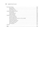
Figure 6.1 Overall view of a typical digital signature scheme.
PUBLIC-KEY INFRASTRUCTURE 205
= ?
No Yes
Authentication
is verified
Authentication
fails
A (client) B (server)
CA
Session
key
RSA
encryption
DES
Plaintext
One-way
function
H
RSA
decryption
H
CA
h
= H(m)
h
d
A
d
A
K
e
B
K
Y = E
K
(m)
e
B
(B’s public key)
e
A
(A′s public key)
(A
′s private key)
(Certification Authority)
(Certification Authority)
Hash
function
Plaintext
m
d
B
(B′s private key)
H (m)
h
h
′C
Message
digest
RSA
encryption
(h
d
A
)
e
A
Session
key
Session
key
K
K
Ciphertext
m
m
DES
decryption
h
′
Message
digest
MD5
C
e
A
Figure 6.2 Signature and authentication with DES/RSA/MD5 (compatible with PEM method).
it using B’s public key. If A wishes to sign a document, he or she must use the private
key available only to him or her. When B receives a digitally signed message from A,
B must verify its signature. B needs A’s public key for this verification. A should have
high confidence in the integrity of that key.
The scenario of a typical signature scheme is described in Figure 6.1. The following
example is presented to illustrate one practical system (Figure 6.2) applicable to the digital
signature computation for user authentication. The combination of SHA-1 (or MD5) and
RSA provides an effective digital signature scheme. As an alternative, signatures can also
be generated using DSS/SHA-1.
For digital signatures, the content of a message
m is reduced to a message digest with
a hash function (such as MD5). An octet string containing the message digest is encrypted
with the RSA private key of the signer. The message and the encrypted message digest
are represented together to yield a digital signature. This application is compatible with
the Privacy-Enhanced Mail (PEM) method. For digital envelopes, the message is first
encrypted under a DES key with a DES algorithm and then the DES key (message-
encryption key) is encrypted with the RSA public key of the recipients of the message.
The encrypted message and the encrypted DES key are represented together to yield a
digital envelope. This application is also compatible with PEM methods.
Example 6.1 Utilizing the practical signature/authentication scheme shown in Fig-
ure 6.2, the analytic solution is as follows:
206 INTERNET SECURITY
Client A
1. DES encryption of message m:
The 64-bit message
m is
m = 785ac3a4bd0fe12d
The 56-bit DES session key
K is
K = ba0c2b3c484ff9 (hexadecimal)
The 64-bit ciphertext
Y (output of 16-round DES) is
Y = a78791c0c8f0b444
2. RSA encryption of K:
K = 52367725502681081 (decimal)
Split K into blocks of two digits:
K = 05 23 67 72 55 02 68 10 81
Obtain B’s public key e
B
= 79 from CA and choose public modulo n = 3337.
Encrypt every two-bit block of
K as follows:
5
79
(mod 3337) ≡ 270
23
79
(mod 3337) ≡ 2524
.
.
.
81
79
(mod 3337) ≡ 3198
Encrypted K = 0270 2524 1479 0285 1773 3139 2753 3269 3198
This encrypted symmetric key is called the digital envelope.
Send this encrypted key (digital envelope)
K to B.
3. Computation of hash code using MD5:
Compute the hash value
h of m:
h = H(m) = H(785ac3a4bd0fe12d)
= 6a26ee0ed9ce3963ec8b0f98ebda8476 (
hexadecimal)
h = 141100303223912907143183747760118203510 (
decimal)
Choose d
A
= 13 (A’s private key) and compute:
c = h
d
A
PUBLIC-KEY INFRASTRUCTURE 207
Let us break the hash code into two decimal numbers as follows:
h = 1411003032239129071
43 18 37 47 76 01 18 20 35 10
Using d
A
= 13 and n = 851, compute the RSA signature:
1
13
(mod 851) ≡ 1
41
13
(mod 851) ≡ 545
.
.
.
10
13
(mod 851) ≡ 333
c = h
d
A
= 001 669 084 400 400 091 348 719 157 303
635 439 333 047 089 001 439 520 466 084
Send c to B.
A
→ B
Send (ciphertext
Y , encrypted value of K and signed hash code c)toB.
Server B
1. Decryption of secret session key K:
Received encryption key
K:
K = 0270 2524 1479 0285 1773 3139 2753 3669 3198
Choose d
B
= 1019 (B’s private key) and decrypt K block by block:
270
1019
(mod 3337) ≡ 5
2524
1019
(mod 3337) ≡ 23
.
.
.
3198
1019
(mod 3337) ≡ 81
K = 05 23 67 72 55 02 68 10 81
or
K = 52367725502681081 (decimal)
=
ba0c2b3c484ff9 (hexadecimal)
2. Decryption of m using DES:
Ciphertext
Y = a78791c0c8f0b444
Restored DES key K = ba0c2b3c484ff9
208 INTERNET SECURITY
Using Y and K, the message m can be recreated:
m = 785ac3a4bd0fe12d
3. Computation of hash code and verification of signature:
Apply MD5 algorithm to the restored message in order to compute the hash code:
h
= H(m) = H(785ac3a4bd0fe12d)
= 6a26ee0ed9ce3963ec8b0f98ebda8476
Obtain A’s public key e
A
= 61 from CA and apply e
A
to the signed hash value c:
c = 001 669 084 400 400 091 348 719 157 303
635 439 333 047 089 001 439 520 466 084
Using e
A
, compute h = c
eA
as follows:
1
61
(mod 851) ≡ 1
669
61
(mod 851) ≡ 41
.
.
.
084
61
(mod 851) ≡ 10
Hence,h= 1411003032239129071
43 18 37 47 76 01 18 20 35 10
Convert it to the hexadecimal number:
h = 6a26ee0ed9ce3963ec8b0f98ebda8476
Thus, we can easily check h = h
.
Digital signing techniques are used in a number of applications. Since digital signa-
ture technology has grown in demand, its explosive utilisation and development will be
expected to continue in the future. Several applications are considered in the following.
• Electronic mail security: Electronic mail is needed to sign digitally, especially in
cases where sensitive information is being transmitted and security services such as
authentication, integrity and non-repudiation are desired. Signing an e-mail message
assures all recipients that the sender of the information is the person who he or she
claims to be, thus authenticating the sender. For example, the DSS is using MOSAIC
to provide security services for e-mail messages. The DSA has been incorporated into
MOSAIC and is used to digitally sign e-mails as well as public-key certificates. Pretty
Good Privacy (PGP) provides security services as well as data integrity services for
messages and data files by using digital signatures, encryption, compression (zip) and
radix-64 conversion (ASCII Armor). MIME defines a format for text messages being
PUBLIC-KEY INFRASTRUCTURE 209
sent using e-mail. MIME is actually intended to address some of the problems and
limitations of the use of SMTP. S/MIME is a security enhancement to the MIME
Internet e-mail format, based on technology from RSA Data Security. Although both
PGP and S/MIME are on an IETF standards track, it appears likely that PGP will
remain the choice for personal e-mail security for many users, while S/MIME will
emerge as the industry standard for commercial and organisational use.
• Financial transactions: This encompasses a number of areas in which money is being
transferred directly or in exchange for services and goods. One area of financial trans-
actions which could benefit especially from the use of digital signatures is Electronic
Funds Transfer (EFT). Digitally signing EFTs are a way of providing security services
such as authentication, integrity and non-repudiation.
Secure Electronic Transaction (SET) is the most important protocol relating to e-
commerce. SET introduced a new concept of digital signature called dual signatures.
A dual signature is generated by creating the message digest of two messages: order
digest and payment digest. The SET protocol for payment processing utilises cryptog-
raphy to provide confidentiality of information, ensure payment integrity and identity
authentication.
• Electronic filing: Contracting requirements expect certain mandated certificates to be
submitted from contractors. This requirement is often filed through the submission of a
written form and usually requires a handwritten signature. If filings are digitally signed
and electronically filed, digital signatures may be used to replace written signatures
and to provide authentication and integrity services.
One of the largest information submission processes is perhaps the payment of taxes
and the request for tax-related information will require signatures. In fact, the IRS in
the USA is converting many of these processes electronically and is considering use of
digital signatures. The IRS has several prototype under development that utilise digital
signatures generated by using DSA. At present, individuals send their tax forms to
the IRS in bulk transactions. The IRS will require them to sign the bulk transactions
digitally to provide added assurances. In future, the electronically generated tax returns
may be digitally signed. The taxpayer may send the digitally signed electronic form
to the IRS directly or through a tax accountant or adviser.
• Software protection: Digital signatures are also used to protect software. By signing the
software, the integrity of the software is assured when it is distributed. The signature
may be verified when the software is installed to ensure that it was not modified
during the distribution process.
• Signing and authenticating: Signing is the process of using the sender’s private key
to encrypt the message digest of a document. Anyone with the sender’s public key
can decrypt it. A person who wants to sign the data has only to encrypt the message
digest to ensure that the data originated from the sender. Authentication is provided
when the sender encrypts the hash value with the sender’s private key. This assures
the receiver that the message originated from the sender.
Digital signatures can be used in cryptography-based authentication schemes to
sign either the message being authenticated or the authentication challenge used in the
210 INTERNET SECURITY
scheme. The X.509 strong authentication is an example of an authentication scheme
that utilises digital signatures.
Careful selection and appropriate protection of the prime numbers
p and q,ofthe
primitive element
g of p and of the private and public components x and y of each key
are at the core of security in digital signatures. Therefore, whoever generates these keys
and their parameters is a vital concern for security. PCAs are responsible for defining
who should generate these numbers.
When generating the key for itself and its CA, each PCA needs to specify the acceptable
algorithms used to generate the prime numbers and parameters. For example, a larger
p
means more security, but requires more computation in the signing and verification steps.
Thus, the size of
p allows a trade-off between security and performance. Each PCA must
specify the range of
p for itself, its CAs and its end users. The range of p is largest for
the PCA and smallest for the end user.
One-way hash functions and digital signature algorithms are used to sign certificates
and CRLs. They are used to identify OIDs for public keys contained in a certificate.
SHA-1 is the preferred one-way function for use in the Internet PKI. It was developed by
the US government for use with both the RSA and DSA signature algorithms. However,
MD5 is used in other legacy applications, but it is still reasonable to use MD5 to verify
existing signatures. RSA and DSA are the most popular signature algorithms used in the
Internet. They combine RSA with either MD5 or SHA-1 one-way hash functions; DSA
is used in conjunction with the SHA-1 one-way hash function. The signature algorithm
with the MD5 and RSA encryption algorithm is defined in PKCS#1 (RFC 2437). The
signature algorithm with the SHA-1 and RSA encryption algorithms is implemented using
the padding and encoding mechanisms also described in PKCS#1 (RFC 2437).
6.3 Functional Roles of PKI Entities
This section describes the functional roles of the whole entities at all levels within the
PKI. It also describes how the PAA, PCAs, CAs and ORAs perform.
6.3.1 Policy Approval Authority
The PAA is the root of the certificate management infrastructure. This authority is known
to all entities at all levels in the PKI and creates the overall guidelines that all users, CAs
and subordinate policy-making authorities must follow.
The PAA approves policies established on behalf of subclasses of users or communities
of interest. It is also responsible for supervising other policy-making authorities.
Figure 6.3 illustrates the PAA functions and their performances. Each PAA performs
the following functions:
• Publishes the PAA’s public key.
• Sets the policies and procedures that entities (PCAs, CAs, ORAs and users) of the
infrastructure should follow.
• Sets the policies and procedures, if any, for a new PCA to join the PKI.
TEAMFLY
Team-Fly
®
PUBLIC-KEY INFRASTRUCTURE 211
PAA functions
Publication
of PAA’s
public key
Policy making
for all entities
Procedures
for joining a
new PCA
Generation of
PCA’s
certificates
Authentication
for revocation
request
Generation of CRLs
for all issuing
certification
Archiving of
certificates, CRLs
and PCA’s policies
Publication of all
PCA’s policies
Deposition of
certificates
and CRLs in
the directory
Locality
information
of PCAs
Specification
for revocation
of PCA’s
certificate
Authentication of
subordinate PCAs and
cross-certification of
international
infrastructure root
Figure 6.3 Illustration of PAA functions.
• Carries out identification and authentication of each of its subordinate PCAs and
national or international infrastructure roots and judges the proper measures to be
taken for cross-certification.
• Generates certificates of subordinate PCAs and of national or international infrastruc-
ture roots to be cross-certified.
• Publishes identification and locality of subordinate PCAs such as directory name,
e-mail address, postal address, phone number, fax number, etc.
• Receives and publishes policies of all subordinate PCAs.
• Specifies information required from subordinate PCAs for a revocation request of the
PCA’s certificate.
• Receives and authenticates revocation requests concerning certificates it has generated.
• Generates CRLs for all the certificates it has issued.
• Archives certificates, CRLs, audit files and PCA’s policies.
• Deposits the certificates and the CRLs it generates in the directory.
212 INTERNET SECURITY
6.3.2 Policy Certification Authority
PCAs are formed by all entities at the second level of the infrastructure. Each PCA
describes the users whom it serves. All PCAs have both policy and certification respon-
sibilities, and must publish their security policies, procedures, legal issues, fees, or any
other subjects they may consider necessary. For PCAs, the users may be people who are
affiliated to an organisation or part of a specific community, or a non-human entity. All
PCA security policies are published and stored on an end user’s local database. Each PCA
performs the following functions as illustrated in Figure 6.4.
• Publishes its identification and locality information, such as directory name, e-mail
address, postal address, phone number, fax number, etc.
PCA functions
Publication of its
identification and locality
information (directory
name, e-mail address, postal
address, phone number, fax
number, etc.)
Publication of the
identification
and locality
information of
its subordinate
CAs
Publication of the plans
for which it serves
Publication of its
security policy
and procedures
for related items
Carrier role of
identification and
authentication of its
subordinates
Generate and
manage certificates
of subordinate CAs
Delivery of its
own public key
and that of PAA to
its subordinates
Specification of
procedures and
information required to
validate certificate
revocation requests
Delivery of
certificates
and CRLs it
generates to
the directory
Archiving certificates,
CRLs, audit fields,
and its signed policy
if changed
Generation of CRLs for
all the certificates it has
issued
Receipt and
authentication of
revocation requests
Figure 6.4 Illustration of PCA functions.
PUBLIC-KEY INFRASTRUCTURE 213
• Publishes identification and locality information of its CAs.
• Publishes who it plans to serve.
• Publishes its security policy and procedures which specify the following items:
– Who generates key variables
p, q, g, x and y.
– The ranges of allowed sizes of
p for itself, its CAs and end users.
– Identification and authentication requirements for the PCA, CAs, ORAs and end
users.
– Security controls at the PCA and CA systems that generate certificates and CRLs.
– Security controls at ORA systems.
– Security controls for every user’s private key.
– The frequency of CRL issuance.
– The constraints it imposes on naming schemes.
– Audit procedures.
• Carries out identification and authentication of each of its subordinates.
• Generates and manages certificates of subordinate CAs.
• Delivers its own public key and that of PAA to its subordinates.
• Specifies procedures and information required to validate certificate revocation
requests.
• Receives and authenticates revocation requests concerning certificates it has generated.
• Generates CRLs for all the certificates it has issued.
• Archives certificates, CRLs, audit files, and its signed policy if changed.
• Delivers the certificates and CRLs it generates to the directory.
6.3.3 Certification Authority
CAs form the next level below the PCAs. The PKI contains many CAs with no policy-
making responsibilities. The majority are plain CAs. A few are CAs that are associated
with PCAs. A CA has any combination of users and ORAs whom it certifies.
The primary function of the CA is to generate, publish, revoke and archive the public-
key certificates that bind the user’s identity with the user’s public key. A better and trusted
way of distributing public keys is to use a CA. CAs are expected to certify the public keys
of users or of other CAs according to PCA and PAA policies. The CAs ensure that all
key parameters are in the range specified by the PCA. Thus, CAs either create key pairs
that satisfy the PCA regulations or they examine user-generated keys to ascertain whether
they fit within the required range assignment. Referring to Figure 6.5, a CA performs the
following functions:
• Publishes and augments PCA policy.
• Carries out identification and authentication of each of its subordinates.
• Generates and manages certificates of subordinates.
• Delivers its own public key and its predecessor’s public keys.
• Verifies ORA certification requests.
• Returns certificate creation confirmations or new certificates to requesting ORA.
• Receives and authenticates revocation requests concerning certificates it has generated.
• Generates CRLs for all the certificates it has issued.
214 INTERNET SECURITY
CA functions
Delivery of
PCA policy
Archiving of
certificates, CRLs
and audit files
Return of certficate
confirmations to
requesting ORA
Generation of
CRLs
Verification of
ORA certification
request
Carrier role of
identification or
authentication for
users
Receiving and
authenticating
revocation requests
Delivery of public
keys of issuing CA
and CA’s
predecessors
Issuance of
certificates
for users
Directory to store
certificate and CRLs
Figure 6.5 Functions of certificate authority (CA).
• Archives certificates, CRLs and audit files.
• Delivers the certificates and the CRLs it generates to the directory.
6.3.4 Organisational Registration Authority
The ORA is the interface between a user and a CA. The prime function that an ORA
performs is user identification and authentication on behalf of a CA and it delivers the
CA-generated certificate to the end user. After authenticating a user, an ORA transmits a
signed request for a certificate to the appropriate CA. In response to an ORA request for
key certification, the CA returns a certificate to the ORA. The ORA passes the certificate
on to the user. Thus, an ORA’s sole task is to help a user who is far from the user’s CA
to register with that CA and to obtain a public-key certificate. ORAs must pass certificate
revocation reports timely and accurately to a CA. In order to verify the signature on the
information at a future time, ORAs must archive the public key or the certificate associated
with the signer. The ORA uses a signed message to inform the CA of the need to revoke
the certificate and to issue a new one. Nowadays RA is preferred for simple use rather
than ORA. An ORA performs the following functions that are illustrated in Figure 6.6:
• Carries out identification and authentication of users.
• Sends user identification information and the user’s public key to the CA in a signed
message.
• Receives and verifies certificate creations or new certificates from the CA.
PUBLIC-KEY INFRASTRUCTURE 215
ORA functions
Carry out identification
and authentication of users
Send user’s identification
information and public key to
the CA
Receive and verify
certificate creations or new
certificates from the CA
Deliver CA’s public key and its
Predecessor’s public key to the user
Receive certificate revocation requests, verify the
validity of the requests, and if valid, send the request
to the CA
Figure 6.6 Illustration of ORA functions.
• Delivers the CA’s public key and its predecessor’s public keys as well as the certificate
to the user if returned.
• Receives certificate revocation requests, verifies the validity of the requests, and if
valid, sends the request to the CA.
6.4 Key Elements for PKI Operations
This section describes operational concepts of the PKI. In order to comprehend the overall
PKI operation, one must understand how it conducts its various activities. Each activity
is broken down into functional steps. The resources required for each functional step
within each activity must be defined. The resources required for an activity are presented
in relation to the entities such as User, KG, CA, ORA, PCA or Directory. The steps
associated with PKI activities are applied to all PKI relationships: User–CA, User–ORA,
ORA–CA, CA–PCA and PCA–PAA.
This section also presents the architectural structures for the PKI certificate manage-
ment infrastructure. These structures should allow users to establish chains of trust that
contain no more than a few certificates in length. The functions and responsibilities of the
CAs and PCAs are briefly reviewed and then how the CAs are interconnected to permit
establishment of reliable certification paths. Some major activities associated with the PKI
operations are presented subsequently.
216 INTERNET SECURITY
6.4.1 Hierarchical Tree Structures
Chains of trust follow a strict tree hierarchy with a root CA (PAA or PCA) to which all
trust is referenced. Each CA certifies the public keys of its users and the public key of the
root CA is distributed to all PKI entities. Thus every entity is linked to the root CA via a
unique trust path. Figure 6.7 depicts such a tree structure. A number of hierarchies may be
joined together by cross-certifying their root CA directly or using bridge CAs. Figure 6.8
illustrates a bridge-type scheme joining a hierarchical tree structure to a mesh structure.
PAA
(root CA)
PCA PCA
CACA
CA
CA
U1 U2 U3
U4 U5 U6 U7 U8
RA
Figure 6.7 Hierarchical tree structure.
RA
Bridge CA
Root
CA
Root
CA
CA CA
U1 U3
U4
CA CA
U8
U7U6
CA
Hierarchical structure Mesh structure
U2
U9
U5
Figure 6.8 A mixed structure using a bridge CA.
PUBLIC-KEY INFRASTRUCTURE 217
With a mesh structure, entities may be connected via several chains of trust. PGP is
a PKI that uses a mesh structure, with every entity acting as their own CA. Gateway
structures are new structure appearing in VPN applications. In a gateway structure, each
domain is separated and relies on its gateway to provide external PKI services. Figure 6.9
depicts a gateway structure with three cross-certified gateways through which the trust of
the network is channelled. Horizontal structures offer improved robustness to penetration
by distributing the trust path horizontally. Multiple platform structures can be used to
introduce redundancy into a PKI structure and thus reduce risk. The public key of each
user is authenticated in each platform. This is a particular advantage with hierarchical
structures because it can remove a single point of failure.
6.4.2 Policy-making Authority
Chains of trust are based on appropriate policies at all levels in the infrastructure. Asso-
ciated with the entire PKI is a policy-establishing authority which will create the overall
guidelines and security policies that all users, CAs and subordinate policy-making author-
ities must follow.
• The PAA has the responsibility of supervising other policy-making authorities. The
PAA will approve policies established on behalf of subclasses of users or of commu-
nities of interest.
• The PCAs will create policy details that expand or extend the overall PAA policies.
Each PCA establishes policy for a single organisation or for a single community of
interest. PCAs must publish their security policies, procedures, any legal issues, any
fees or any other subjects that they consider necessary.
• The CAs are expected to certify the public key of end users or of other CAs in
accordance with PCA and PAA policies. The CA must ensure that all key parameters
Root CA
CA
CA
Gateway 1 Gateway 2
Gateway 3
U11 U12 U13 U14
U1
U2
U3
U4
Root CA
CA CA
CA
U8 U9
U7
U5
U6
U10
Figure 6.9 A gateway structure.
218 INTERNET SECURITY
are in the range specified by the PCA. Therefore, the CA either creates key pairs
according to the PCA regulations or examines the user-generated keys to ascertain
that they satisfy the requirements of the range. A few CAs are associated with PCAs,
but the majority are plain CAs at all points in the infrastructure.
• The ORA submits a certificate request on behalf of an authenticated entity. The CA
returns the signed certificate or an error message to the ORA. The ORA or certificate
holder requests revocation of a certificate to the issuing CA. The CA responds with
acceptance or rejection of the revocation request. Certificate Revocation Lists (CRLs)
contain all revoked certificates that CAs have issued and have not expired. The CA
returns the signed certificate and its certificate or an error message to the end user.
The CA posts a new certificate and CRL to the repository.
6.4.3 Cross-certification
Suppose the CA has its private/public-key pair and the X.509 certificate issued by the
CA. If a user knows the CA’s public key, then the user can decrypt the certificate with
the CA’s public key and verify the X.509 certificate signed by the CA. Thus the user can
recover his or her public key contained in the X.509 certificate; the user’s public key is
verified as illustrated in Figure 6.10.
CA
X.509
certificate
Signature
SHA-1
E
m
E
KS
c
h
E
p
RSA encryption
D
p
K
d
K
e
KS
c
RSA decryption
D
KP
c
SHA-1
E
h
Compare
D
E
(ID, KP
u
)
KP
u
KS
u
USER
(ID, KP
u
)
KP
u
: User’s public key
KS
u
: User’s private key
K
e
: RSA public key
SHA-1 : One-way hash function
E/D : Public-key encryption/decryption
m : X.509 certificate
KP
c
: CA’s public key
KS
c
: CA’s private key
K
d
: RSA private key
h : Certificate message digest
Ep/Dp : RSA encryption/decryption
ID : User ID
m
Figure 6.10 Certification of the user’s public key.
PUBLIC-KEY INFRASTRUCTURE 219
The signature algorithm and one-way hash function used to sign a certificate are indi-
cated by use of an algorithm identifier or OID. The one-way hash functions commonly
used are SHA-1 and MD5. RSA and DSA are the most popular signature algorithms used
in the X.509 Public-Key Infrastructure (PKIX).
Because no one can modify the certificate, it can be placed in a directory without any
special effort made to protect the certificate. A user can transmit his or her certificate
directly to other users. In the case when a CA encompasses several users, there must be
a common trust of that CA. These users’ certificates can be stored in the directory for
access by all users.
When all users in a large community subscribe to the same CA, it may not be prac-
tical for these users. With many users, it is more desirable to have a limited number of
participating CAs, each CA securely providing its public key to the subordinate users.
Since the CA signs the certificates, each user must have a copy of the CA’s public key
to verify signatures. The CA should provide its public key to each user in an absolutely
secure way so that the user has confidence in the associated certificates.
Suppose there are two users A and B. A certificate is defined in the following notation:
X
<< A >>
which means the certificate of user A issued by certification authority X. Consider Fig-
ure 6.11(a) which depicts a simple example, where X
1
and X
2
represent two CAs. User A
uses a chain of certificates to obtain user B’s public key. The chain of certificates is
expressed as:
X
1
X
2
X
2
B
Similarly, user B can obtain A’s public key with the reverse chain such that:
X
2
X
1
X
1
A
This scheme need not be limited to a chain of two certificates. An arbitrarily long path
of CAs can produce a chain. All the certificates of CAs by CAs need to appear in the
directory, and the user needs to know how they are linked to follow a path to another
user’s public-key certificate. X.509 suggests that CAs be arranged in a hierarchy so that
tracing is straightforward.
Figure 6.11(b) is an example of such a hierarchy. The connected ellipses circles indi-
cate the hierarchical relationship among CAs; the associated boxes indicate certificates
maintained in the directory for each CA entry. Four users are indicated by circles. In this
example, user A can acquire the following certificates from the directory to establish a
certification path to user B:
X
Y Y W W U U V V B
When A has obtained these certificates, A can unwrap the certification path in sequence
to recover a trusted copy of B’s public key. Using this public key, A can send encrypted
messages to B. If A wishes to receive encrypted messages back from B, or to sign
220 INTERNET SECURITY
(b)
(a)
X
1
X
2
X
2
<<X
1
>> X
1
<<X
2
>>
A
B
X
1
<<A>> X
2
<<B>>
Z
W
Y
U
X V
A
C B D
X<<A>> X<<C>> V<<B>> V<<D>>
Y<<X>>
X<<Y>>
X<<V>>
U<<V>>
V<<U>>
V<<X>>
W<<U>>
U<<W>>
W<<Y>>
Y<<W>>
Z<<W>>
W<<Z>>
Figure 6.11 X.509 hierarchical scheme for a chain of certificates.
messages sent to B, then B will require A’s public key, which can be obtained from the
following certification path:
V
U U W W Y Y X X A
B can obtain this set of certificates from the directory, or A can provide them as part
of the initial message to B.
CAs may issue certificates to other CAs with appropriate constraints. Each CA deter-
mines the appropriate constraints for path validation by its users. After obtaining the other
CA’s public key, the CA generates the certificate and posts it to the repository.
The procedure for certifying path validation for the PKIX describes the verification
process for binding both the subject distinguished name and the subject public key. The
binding is limited by constraints that are specified in the certificates which comprise
the path.
TEAMFLY
Team-Fly
®
PUBLIC-KEY INFRASTRUCTURE 221
6.4.4 X.500 Distinguished Naming
X.509 v1 and v2 certificates employ X.500 names exclusively to identify subjects and
issuers. The information stored in X.500 directories comprises a set of entries. Each entry
is associated with a person, an organisation or a device which has a distinguished name
(DN). The directory entry for an object contains values of a set of attributes pertaining
to that object. For example, an entry for a person might contain values of attributes of
type common name, telephone number, e-mail address and job title. All X.500 entries
have the unambiguous naming structure called the Directory Information Tree (DIT) as
shown in Figure 6.12. The DIT has a single conceptual root and unlimited further vertices
with distinguished names. The DN for an entry is constructed by joining the DN of its
immediate superior entry in the tree with a relative distinguished name (RDN).
Suppose a staff member of the organisation has an X.500 name. If this person leaves
the corporation and a new staff member joins the corporation and is reassigned the same
X.500 name, this may cause authorisation ambiguities in the access control of X.500 data
objects. The idea of the unique identifier fields in the X.509 v2 certificate format is that
a new value could be put in this field whenever an X.500 name is reused. Unfortunately,
unique identifiers do not contribute a very reliable solution to this problem due to the
managing difficulty. A much better approach is to systematically ensure that all X.500
Root
C 2 O
C 2 G
C 1 G
C1
C 1 O
C2
RDN
RDN
RDN
Attribute
Attribute
Common name (CN)
Telephone number
E-mail address
C1, C2: Name of country
G : Government of C1 or C2
O : An organisation in C1 or C2
CN : Common name
RDN : Relative distinguished name
Job title
Figure 6.12 The DIT example of X.500 naming.
222 INTERNET SECURITY
names are unambiguous. This can be achieved by an RDN and a new attribute value,
ensuring that employee numbers are not reused over time.
6.4.5 Secure Key Generation and Distribution
Each user must assure the integrity of the received key and must rely on the PKI to supply
the public keys generated from associated certificates.
Consider a scenario in which a user’s public/private-key pair can be generated, certified
and distributed. There are two ways to consider:
• The user generates his or her own public/private-key pair. In this way, the user is
responsible for ensuring that he or she used a good method for generating the key
pair. The user is also responsible for having his or her public key certified by a CA.
The advantage for the user of generating the key pair is that the user’s private key is
never released to another entity. This allows for the provision of true non-repudiation
services. The user must store his or her private key in a tamperproof secure location
such as on a smart card, floppy disk or PCMCIA card.
• A trusted third party generates the key pair for the user. This method assumes that
security measures are employed by the third party to prevent tampering. To obtain a
key pair from another entity such as a centralised Key Generator (KG), the user goes
to the KG and requests the KG to generate a key pair. This KG will be collocated
with either a CA or an ORA. The KG generates the key pair and gives the public and
private keys to the user. The private key must certainly be transmitted to the user in
a secure manner such as on a token which might be a smart card, a PCMCIA card or
an encrypted diskette. It is not appropriate for the KG to send the user’s public key
to the CA for certification. It must give the copy of the public key to the user so that
he or she can be properly identified during the certificate generating procedure. The
KG also automatically destroys the copy of the user’s private key once it has been to
the user.
If key generation is conducted by a trusted third party on behalf of the user, it is
necessary to assure the integrity of the public key and the confidentiality of the private key.
Therefore, the generation and distribution of key pairs must be done in a secure fashion.
CA keys are generated by the CA itself. Thus, the PAA, the PCAs and CAs all generate
their own key pairs. An ORA can generate its own key pair or have it generated by a
third party depending upon PCA policy. A PCA has its public key certified by the PAA.
At that time, it can obtain the PAA’s public key. A CA’s public key is certified by the
appropriate PCA.
Besides these elements, other important key elements for PKI operations are X.509
certificates, certificate revocation lists, and certification path validation. These subjects
are covered in the following three sections, respectively.
6.5 X.509 Certificate Formats
These formats are described in this section and an algorithm for X.509 certificate path
validation is also discussed. The specification profiles the format of certificates and cer-
tificate revocation lists for the Internet PKIX. Procedures are described for processing
PUBLIC-KEY INFRASTRUCTURE 223
certification paths in the Internet environment. Encryption and authentication rules are
provided with well-known cryptographic algorithms.
X.500 specifies the directory service. X.509 describes the authentication service using
the X.500 directory. A standard certificate format of X.509 which was defined by ITU-T
X.509 (formerly CCITT X.509) or ISO/IEC/ITU 9594-8 was first published in 1988 as
part of the X.500 directory recommendations. The certificate format in the 1988 standard
is called the version 1 (v1) format. When X.500 was revised in 1993, two more fields
were added, resulting in the version 2 (v2) format. These two fields are used to support
directory access control.
The Internet Privacy Enhanced Mail (PEM), published in 1993, includes specifications
for a PKI based on the X.509 v1 certificate (RFC 1422). Experience has shown that the
X.509 v1 and v2 certificate formats are not adequate enough in several aspects. It was
found that more fields were needed to contain necessary information for PEM design
and implementation. In response to these new requirements, ISO/IEC/ITU and ANSI X9
developed the X.509 v3 certificate format. It extends the v2 format by including additional
fields. Standardisation of the basic format of X.509 v3 was completed in June 1996.
The standard extensions for use in the v3 extensions field can convey data such as
subject identification information, key attribute information, policy information and cer-
tification path constraints. In order to develop interoperable implementations of X.509
v3 systems for Internet use, it is necessary to specify a profile for use of the X.509 v3
extensions for the Internet.
X.509 defines a framework for the provision of authentication services by the X.500
directory to its users. X.509 is an important standard because the certificate structure and
authentication protocols defined in X.509 are used in a various areas. The X.509 certificate
format is used in S/MIME for e-mail security, IPsec for network-level security, SSL/TLS
for transport-level security, and SET for secure payment systems.
6.5.1 X.509 v1 Certificate Format
As stated above, the X.509 certificate format has evolved through three versions: version 1
in 1988, version 2 in 1993 and version 3 in 1996. We start by describing the v1 format.
This format contains information associated with the subject of the certificate and
the CA who issued it. The certificate (value equals 0) contains a version number, a serial
number, the CA signature algorithm, the names of the subject and issuer, a validity period,
a public key associated with the subject, and a issuer’s signature. These basic fields are
as shown in Figure 6.13. The certificate fields are interpreted as follows:
• Version: In this field the format of the certificate is identified as the indicator of version
1, 2 or 3 format. The 1988 X.509 certificate v1 format is used only when basic fields
are present. The value of this field in a v1 format is assigned as ‘0’. The v2 certificate
format is assigned the value ‘1’. The value of this field is 2, signifying a v3 certificate.
• Serial number: This is an integer assigned by the CA to each certificate. In other
words, this field contains a unique identifying number for this certificate, assigned by
the issuing CA. The issuer must ensure that it never assigns the same serial number
to two distinct certificates.
224 INTERNET SECURITY
Certificate fields Interpretation of contents
Version Version of certificate format
Serial number Certificate serial number
Signature algorithm
Signature algorithm identifier
for certificate issuer’s signature
Issuer CA’s X.500 name
Validity period Start and expiry dates/times
Subject name Subject X.500 name
Subject public-key information
Algorithm identifier and subject public-
key value
Issuer’s signature Certificate Authority’s digital signature
Figure 6.13 X.509 version 1 certificate format.
• Signature: The algorithm used by the issuer in order to sign the certificate is specified.
The signature field contains the algorithm identifier for the algorithm used to sign the
certificate.
• Issuer: This field provides a globally unique identifier of the authority signing the
certificate. The syntax of the issuer name is an X.500 distinct name. This field contains
the X.500 name of the issuer that generated and signed the certificate. The DN is
composed of attribute type–attribute value pairs.
• Validity: This field denotes the start and expiry dates/times for the certificate. The
validity field indicates the dates on which the certificate becomes valid (not before)
and on which the certificate ceases to be valid (not after). In other words, it contains
two time and date indications that denote the start and the end of the time period for
which the certificate is valid. The validity field always uses UTCTime (Coordinated
Universal Time) which is expressed in Greenwich Mean Time (Zulu).
• Subject: The purpose of the subject field is to provide a unique identifier of the subject
of the certificate. The syntax of the subject name will be an X.500 DN. This field
contains the name of the entity for whom the certificate is being generated. The field
denotes the X.500 name of the holder of the private key, for which the corresponding
public key is being certified.
• Subject public-key information: This field contains the value of a public key of the
subject together with an identifier of the algorithm with which this public key is to
be used. It includes the subject public-key field and an algorithm identifier field with
algorithm and parameters subfields.
PUBLIC-KEY INFRASTRUCTURE 225
• Issuer’s signature: This field denotes the CA’s signature for which the CA’s private
key is used. The actual signature on the certificate is defined by the use of a sequence
of the data being signed, an algorithm identifier and a bit string which is the actual sig-
nature. The algorithm identifier is used to sign the certificate. Although this algorithm
identifier field includes a parameter field that can be utilised to pass the parameters
used by the signature algorithm, it is not itself a signed object. The parameter field
of the certificate signature is not to be used to pass parameters. When parameters
are used to validate a signature, they may be obtained from the subject public-key
information field of the issuing CA’s certificate.
Experience has shown that the X.509 v1 certificate format is deficient in several respects.
The v2 format extends the v1 format by including two more identifier fields.
6.5.2 X.509 v2 Certificate Format
RFC 1422 uses the X.509 v1 certificate format, which imposes several structural restric-
tions on clearly associating policy information and restricts the utility of certificates. The
X.509 v2 format imposed by RFC 1422 can be addressed using two more fields – issuer
and subject unique identifiers which are illustrated in Figure 6.14. These two added fields
are interpreted as follows:
• Issuer unique identifier: This field is present in the certificate to deal with the possi-
bility of reuse of issuer names over time. In this field, an optional bit string is used
Certificate fields
v1 = v2
(for seven fields)
Issuer unique identifier
Subject unique identifier
v1 = v2
(for the last field)
Interpretation of two more
added fields
Version, serial number, signature
algorithm, issuer, validity period,
subject name, subject public-key
information
To handle the possibility of
reuse of issuer and/or subject names
through time
Issuer’s signature
Figure 6.14 X.509 version 2 certificate format.