Microsoft Press mcsa mcse self paced training kit exam 70 - 293 phần 2 potx
Bạn đang xem bản rút gọn của tài liệu. Xem và tải ngay bản đầy đủ của tài liệu tại đây (834.37 KB, 96 trang )
2-14 Chapter 2 Planning a TCP/IP Network Infrastructure
Lesson 2: Planning an IP Routing Solution
An IP router is a hardware or software device that connects two local area networks
(LANs), relaying traffic between them as needed. Part of designing a network infrastruc-
ture is determining how many LANs you will create and how you will connect them.
When you are designing a small network, routing is not a major consideration because
you can put all your computers on a single LAN. For medium-to-large networks, this is
not a practical solution. You have to create several LANs and then connect them so that
any computer on the network can communicate with any other computer.
Your IP routing plan can be simple or complex, depending on the size of the network
installation, the number of LANs you decide to create, and how you choose to connect the
LANs. A small network might have a single router connecting the LAN to an ISP to provide
network users with Internet access. A large network installation might consist of many dif-
ferent LANs, all connected with routers. The ultimate IP routing scenario is the Internet
itself, which is composed of thousands of networks connected by thousands of routers.
Typically, an IP routing plan specifies how many LANs there will be in your network
installation and how you will connect the LANs. The plan should also specify the types
of routers the network will use, and how the routers will get the information they need
to forward packets to their destinations.
After this lesson, you will be able to
■ Understand router functions
■ Use routers to connect LANs and wide area networks (WANs)
■ Understand the difference between routing and switching
Estimated lesson time: 0 minutes 2
Understanding IP Routing
When a computer on a TCP/IP network transmits a packet, the datagram in the packet
contains the IP address of the destination computer, as well as the address of the
sender. If the destination address is on the same LAN as the sender, the packet travels
directly to that destination. If the destination is on a different network, the sender trans-
mits a packet to a router instead. This router is known as the computer’s default gate-
way. (In TCP/IP parlance, the term gateway is synonymous with router.) You specify
the default gateway address for your computers along with their IP addresses and sub-
net mask during the TCP/IP configuration process.
The default gateway is the interface between the sender’s own network and all the
other connected networks. When the router receives a packet, it reads the destination
address and compares the address to the entries in its routing table. A routing table is
Lesson 2 Planning an IP Routing Solution 2-15
a list of destination addresses, with the information needed to forward traffic to those
destinations. Using the information in its routing table, the router determines where to
send the packet next. The router might be able to transmit the packet directly to its des-
tination (if the router has an interface on the destination network), or it might send the
packet to another router, where the entire process begins again. On a private network,
packets might travel through several routers on the way to a given destination. On the
Internet, packets commonly pass through a dozen routers or more.
Tip To see a list of the routers between your computer and a specific destination address,
you can use the traceroute utility that is provided with most TCP/IP implementations. On com-
puters running the Microsoft Windows operating systems, the traceroute utility is called Trac-
ert.exe. To use it, display a Command Prompt window and type tracert address, where
address is the IP address of a destination computer.
Routers obtain the information in their routing tables in one of two ways. Either an
administrator manually enters the information, which is called static routing, or the
router receives the information automatically from another router using a specialized
routing protocol. This is called dynamic routing. On Internet routers, the routing tables
can be long and complex, but the tables on private network routers are simple.
Creating LANs
Ethernet LANs are typically defined in terms of broadcast domains and collision
domains.
■ A broadcast domain is a group of computers, all of which receive broadcasts
transmitted by any one of the computers in a group. For example, when you con-
nect 100 computers using only Ethernet hubs, any one of those computers can
generate a broadcast and all the other computers will receive it.
■ A collision domain is a group of computers that are connected in such a way that
when any two computers transmit packets at exactly the same time a collision occurs.
The collision destroys both packets and forces the computers to retransmit them.
When you create two LANs and join them using a router, you are creating two separate
broadcast domains, because routers do not forward broadcast transmissions from one
network to another, and two separate collision domains, because packets transmitted
on the same network may collide, but packets on different networks do not.
Planning The reason to split a private network into multiple LANs is to create different
broadcast domains and collision domains.
2-16 Chapter 2 Planning a TCP/IP Network Infrastructure
If you were to have thousands of computers all connected to the same LAN, each com-
puter would have to devote an inordinate amount of time to processing broadcast mes-
sages. In addition, there would be a high collision rate because so many computers
would be contending for the network medium at the same time. More collisions mean
more packet retransmissions. The result would be a slow, inefficient network. By split-
ting that network into multiple LANs, you create individual broadcast and collision
domains, reducing the number of broadcasts each system has to process and the num-
ber of collisions that occur.
Routing and Network Topology Design
In Lesson 3 of Chapter 1, “Planning a Network Topology,” you learned that net-
work designers often split the network into a series of horizontal networks, each
of which is connected to a backbone network using a router. This design pro-
vides an efficient routing solution. No matter how many horizontal networks you
have in your installation, a transmitted packet never has to travel through more than
two routers to get to any destination on the network (as shown in Figure 1-7). Each
packet passes through one router to get from its origin network to the backbone
and through a second router to get from the backbone to the destination network.
Connecting the horizontal networks in series would require packets to pass
through a separate router for each network they traverse.
The number of LANs you create and the number of computers in each LAN
depend on the data-link layer protocol you select for your network. Some proto-
cols have specific limitations on the number of computers they support on a sin-
gle LAN while others have implied limits based on other factors, such as the
maximum number of hubs you can use. In many cases, however, a network’s
LAN configuration is based on geographical or political factors. For example, if
you are designing a network for a multi-story office building, creating a separate
LAN for each floor might be the most convenient solution. In other cases, design-
ers create a separate LAN for each department or division in the organization.
Another advantage of routers is that they can connect networks running completely
different protocols at the data-link layer. Whenever a packet arrives at a router, it trav-
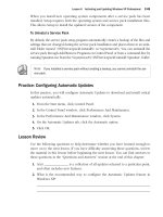
els up through the protocol stack only as high as the network layer (see Figure 2-3).
The router strips off the data-link layer frame from the packet and processes the IP
datagram contained inside. When the router has determined how to forward the data-
gram to its next destination, it repackages the datagram in a new data-link layer frame
prior to transmission. This new frame can be the same as, or different from, the original
frame on the packet when it arrived on the router. So if your network infrastructure
Lesson 2 Planning an IP Routing Solution 2-17
design calls for different data-link layer protocols or different network media to satisfy
the requirements of different users, you can connect those different networks using
routers. You can connect two different types of Ethernet, such as connecting a
100Base-TX Fast Ethernet horizontal LAN (using Category 5 unshielded twisted pair
cable) to a 1000Base-SX Gigabit Ethernet backbone (using fiber-optic cable), or even
connecting an Ethernet LAN to a Token Ring LAN.
Physical
Physical Physical
Data-link
Data-link Data-link
Network
Network Network
Transport
Transport
Session
Session
Presentation
Presentation
Application
Application
Figure 2-3 A router processing network traffic
Creating WANs
In addition to connecting LANs, routers can also connect a LAN to a WAN connection,
enabling you to join networks at different locations. This is the most common applica-
tion for routers today. Every network connected to the Internet uses a router to connect
the private network to an ISP’s network. The ISP in turn has its own routers that pro-
vide the connection to the Internet. Even a simple Windows computer using the Inter-
net Connection Sharing (ICS) feature is functioning as a router.
Some network installations also use routers and WAN connections to join distant
offices. For example, a branch office might be connected to corporate headquarters
using a T-1 line, which is a permanent, digital telephone connection between the two
sites. To connect the networks at those sites, each one has a router connecting it to one
end of the T-1, as shown in Figure 2-4. The T-1 itself then becomes a two-node net-
work, connecting the two remote LANs. A computer at one site that has to send traffic
to a computer at the other site sends its packets to the router on the local network. The
router then forwards the packets over the T-1 to the router at the other site. The second
router then forwards the packets to the LAN in the other office.
2-18 Chapter 2 Planning a TCP/IP Network Infrastructure
Router
T-1
Router
Figure 2-4 Two remote networks connected using routers and a WAN
You will learn later in this chapter that there are alternatives to routers for connecting
LANs at the same site. However, routers are essential for connecting networks using a
WAN. This is because WANs use different data-link layer protocols than LANs. A typical
WAN connection uses a TCP/IP protocol called the Point-to-Point Protocol (PPP) at the
data-link layer. PPP is designed solely for connections between two nodes. With PPP,
unlike Ethernet, there is no contention for the network medium and no need for
packet addressing. The control overhead of the PPP is therefore much lower than that
of Ethernet or Token Ring. The routers not only provide the interface to the WAN, they
also repackage the datagrams for transmission over a different type of network.
Using Routers
The routers you use to connect your LANs can take many different forms. Some routers
are software products. A Windows Server 2003 computer is capable of functioning as
a router, providing you install two network interface adapters in the computer and con-
figure RRAS to function as a LAN router. Windows Server 2003 can also function as a
router connecting a LAN to the Internet. The only differences between the two router
functions are the RRAS configuration and the fact that one of the network interfaces is
a modem or other device providing a WAN connection to an ISP.
On most networks, routers are more likely to be separate hardware devices than standard
computers. Stand-alone routers are available in many sizes and price ranges. The smallest
and most inexpensive routers are devices the size of an external modem that are designed
to connect a home or small business LAN to the Internet. More elaborate Internet access
routers are designed to support larger networks. Most of these routers can use NAT so that
the clients on the private network can use unregistered IP addresses.
Planning Routers for connecting LANs tend to be high-end devices and are frequently mod-
ular. This type of device consists of a router frame, which you typically install in a data center
and populate with modules that provide interfaces to your various networks. The advantage of
this design is that you can connect LANs (or WANs) of any type by purchasing the appropriate
modules and inserting them into the frame.
Lesson 2 Planning an IP Routing Solution 2-19
Using Switches
While routers are necessary for connecting distant networks with WANs, today’s net-
works do not use them for connecting LANs together as often as they used to. Switches
have largely replaced routers on internal networks. A switch is a network connection
device similar in appearance to a hub but with different internal functions.
A typical Ethernet hub is strictly a physical layer device. Electrical (or fiber-optic)
signals generated by devices on the network enter the hub through one of its ports.
The hub then amplifies the signals and transmits them through all the other ports
simultaneously. The hub does not read the contents of the data packets it forwards or
even recognize that they are data packets. The hub’s function is strictly electrical (or
photonic). It has no intelligence.
Switches receive signals from network devices in the same way as a hub, but the
switch is intelligent and can read the contents of the data packets it receives. The
switch reads the destination address in each incoming packet, amplifies the signals like
a hub, and then forwards the packet, but only through the port providing the connec-
tion to the packet’s destination.
When you connect a group of computers to a hub, every packet transmitted by every com-
puter is forwarded to every other computer. This means that the network interfaces in the
computers spend a significant amount of time reading the addresses of incoming packets
and discarding them because they are intended for another destination. Connect the same
group of computers to a switch, and the amount of traffic on the network is reduced sub-
stantially because packets travel directly from the source only to their destinations and
nowhere else. Each pair of computers on the network has, in effect, a dedicated connec-
tion between them, using the full bandwidth of the network medium. There is less conten-
tion for the network medium, and therefore there are fewer collisions.
You can use switches in place of hubs on your individual horizontal networks. These
are called workgroup switches or switching hubs. As a replacement for routers, how-
ever, you can also use a single high-performance switch in place of a backbone net-
work. By using switching hubs on your horizontal networks and connecting them to a
single backbone switch, you create a network infrastructure in which every computer
can open a dedicated connection to any other computer. For larger networks, you can
add a third level of switches, connecting your workgroup switches to a departmental
switch and your departmental switches to a backbone switch.
2-20 Chapter 2 Planning a TCP/IP Network Infrastructure
Off the Record You can connect standard hubs to departmental or backbone switches,
providing each horizontal network with a dedicated connection to every other horizontal net-
work. This is not as efficient as a fully switched network, but it provides a performance
improvement over routers and a backbone that all computers in the enterprise share.
Real World Switches, Routers, and Performance
Because they are more intelligent, switches are more expensive than standard
Ethernet hubs, but they are less expensive than comparable routers. Routing is a
more complicated task than switching because a router has to strip off each
packet’s data-link layer frame, process the information in the IP datagram, and
then package the datagram in a new frame before transmitting it. A basic switch,
in contrast, only has to read the data-link layer address in each packet and for-
ward it to the appropriate port. For this reason, switching is also far faster than
routing.
Replacing the routers on an existing network with switches usually results in an
increase in performance. Designing a network from the outset to use switches
enables you to achieve peak performance from the network equipment you
select. Even a standard 10-megabit-per-second (Mbps) Ethernet network can yield
exceptional performance when each workstation has a dedicated, full-bandwidth
connection to every other workstation.
Combining Routing and Switching
Unlike routers, which operate at the network layer, switches are data-link layer
devices, and this presents a new problem. By connecting LANs with switches, you are
essentially creating one huge LAN. Although switching eliminates the problem of hav-
ing one huge collision domain, all computers on the network are still in the same
broadcast domain. When a computer on the network transmits a broadcast message,
every computer on the entire network receives it. This type of setup can consume large
amounts of bandwidth unnecessarily.
The solution to this problem lies in a switch’s ability to create virtual LANs, or VLANs.
A virtual LAN is a group of computers on a switched network that functions as a sub-
net. When one computer in a VLAN generates a broadcast transmission, only the other
computers in the same VLAN receive it. Network administrators create VLANs in the
switch by specifying the addresses of the computers in each subnet.
Lesson 2 Planning an IP Routing Solution 2-21
Planning One big advantage to creating subnets with VLANs is that the computers in a
subnet can have physical locations anywhere in the enterprise. With VLANs, you can create
subnets based on criteria other than physical proximity, such as membership in a workgroup
or department.
VLANs are logical constructions that form an overlay to the switched network. The com-
puters are still switched, but the VLANs enable them to behave as though they are
routed. Further difficulty arises, however, when computers on different VLANs have to
communicate with each other. In this case, some element of actual routing is necessary,
and various types of switches treat this requirement in different ways. Switches that are
strictly layer 2 (that is, data-link layer) devices sometimes have a port for a connection to
a router. This type of device operates under a “switch where you can, route where you
must” philosophy. The device switches all traffic between computers on the same VLAN,
but it sends all traffic between computers on different VLANs to the router for processing.
Another solution to this problem is most commonly called layer 3 switching, although
specific switching hardware manufacturers have other names for the technique, includ-
ing multilayer routing and cut-through routing. A layer 3 switch has the capabilities of
a switch and a router built into a single device. Rather than examine the datagram
information for every packet, a layer 3 switch examines the first packet in each series
to determine its final destination, and then uses standard layer 2 switching for the sub-
sequent packets sent to the same destination. The philosophy for this type of device is
“route once, and switch afterwards.”
Workgroup and departmental switches are relatively simple devices. Some manufactur-
ers have lines of hubs and switches that are outwardly identical, differing only in their
internal construction. Layer 3 switches are much more complex, typically taking mod-
ular form like high-end routers. Installing this type of switch enables you to connect
different types of horizontal networks, providing essentially the same functions as a
router, but with greater speed and efficiency.
2-22 Chapter 2 Planning a TCP/IP Network Infrastructure
Practice: Designing an Internetwork
In the following exercises, the diagrams represent a network installation that consists
of four independent LANs. Working directly on the diagrams, add the components nec-
essary to fulfill the requirements given in each exercise. Be sure to add all the neces-
sary cables, hubs, routers, or switches, and label them accordingly. Don’t forget to label
the device connecting the computers in each LAN as well.
Exercise 1: Internetwork Design with a Single Broadcast Domain and Multiple
Collision Domains
In the following diagram, add the components needed to connect the LANs to an inter-
network that consists of a single broadcast domain and several collision domains.
Lesson 2 Planning an IP Routing Solution 2-23
Exercise 2: Internetwork Design with Multiple Broadcast and Collision Domains
In the following diagram, add the components needed to connect the LANs in an inter-
network that consists of five broadcast domains and five collision domains.
Lesson Review
The following questions are intended to reinforce key information presented in this
lesson. If you are unable to answer a question, review the lesson materials and try the
question again. You can find answers to the questions in the “Questions and Answers”
section at the end of this chapter.
1. Replacing the hubs and routers on an internetwork with switches creates a net-
work that has which of the following?
a. One broadcast domain and one collision domain
b. One broadcast domain and multiple collision domains
c. One collision domain and multiple broadcast domains
d. Several collision domains and several broadcast domains
2-24 Chapter 2 Planning a TCP/IP Network Infrastructure
2. Specify the OSI reference model layer at which each of the following devices
operates.
a. A switch
b. A router
c. A hub
3. Which of the following Windows Server 2003 TCP/IP configuration parameters
specifies the address of a router?
a. Preferred DNS server
b. Subnet mask
c. Default gateway
d. IP address
4. When you replace the routers on an internetwork with switches that include no
VLAN or layer 3 capabilities, which of the following is a possible reason for poor
network performance?
a. Excessive collisions
b. Excessive broadcast traffic
c. Excessive number of workstations on the LAN
d. Excessive number of collision domains
Lesson Summary
■ Large networks typically consist of multiple LANs connected by routers. Routers
are network layer devices that enable communication between the networks while
maintaining separate broadcast and collision domains.
■ Routers can take the form of software or hardware, and range from Routing and
Remote Access in Windows Server 2003 to inexpensive Internet access devices to
expensive modular installations that support large networks.
■ A typical network design consists of several horizontal networks, all connected to
a single backbone network.
■ A switch is a data-link layer device that intelligently forwards traffic to specified
destinations. Switches can replace many routers in your network infrastructure
design, creating a network that is more efficient and economical.
■ Replacing routers with switches creates a network with a single broadcast domain.
Virtual LANs are logical subnets that exist inside switches, enabling you to limit the
propagation of broadcasts throughout the network.
Lesson 3 Planning an IP Addressing and Subnetting Strategy 2-25
Lesson 3: Planning an IP Addressing and Subnetting Strategy
Once you have determined what types of IP addresses your network will use and have
decided how many LANs you are going to create and how you’re going to connect
them, you can begin the process of calculating the network’s IP addresses, subnet
masks, and default gateway addresses. You can also plan how the network administra-
tors are actually going to perform the TCP/IP configuration tasks.
After this lesson, you will be able to
■ Understand how to subnet a network
■ Calculate a subnet mask
■ Calculate IP addresses on subnetted networks
Estimated lesson time: 0 minutes 3
Obtaining Network Addresses
In Lesson 1 of this chapter, you learned about the circumstances under which to use
registered and unregistered IP addresses, and you have presumably used this informa-
tion to design a network infrastructure in which the computers use the appropriate
address types. If some or all of your computers require registered IP addresses, you can
obtain them in one of two forms, depending on how many addresses you need.
Planning If you need only a few registered addresses, you can obtain them singly from your
ISP along with an appropriate subnet mask, although you will almost certainly have to pay an
extra monthly fee for them. If the computers requiring the registered address are all on the
same LAN and must communicate with each other, be sure that you obtain addresses in the
same subnet. If you need a large number of registered IP addresses, you can obtain a net-
work address from the ISP and use it to create as many host addresses as you need.
A network address is the network identifier portion of an IP address plus a subnet
mask. For example, if your ISP were to assign you the network address 192.168.65.0,
with a subnet mask of 255.255.255.0, you can assign IP addresses ranging from
192.168.65.1 to 192.168.65.254 to your computers. The network address you receive
from the ISP depends on the class of the address and on the number of computers you
have requiring registered addresses.
Off the Record In practice, the network address your ISP assigns you will not be part of
the private address range used in this example. Also, it will probably be more complex than
the address shown here, because the ISP will be assigning you only a small portion of the
addresses assigned to them.
2-26 Chapter 2 Planning a TCP/IP Network Infrastructure
Understanding IP Address Classes
The IANA divides the IP address space into three basic classes. Each class provides a
different number of possible network and host identifiers, and therefore, each is suit-
able for installations of a specific size. The three classes, and the relative sizes of the
network and host identifiers, are shown in Figure 2-5.
8
16
24
Host Identifier
Network Identifier
Network
Identifier
Host Identifier
Class A
Class B
Class C
Network Identifier
Host Identifier
Figure 2-5 IP address classes
Table 2-1 provides additional information about each of the address classes, including
the value of the first binary bits and the first decimal byte in each class. The value of
the first bits and first byte are what you use to determine the class of a particular net-
work address. The table also specifies the number of bits in the network and host iden-
tifiers for each class, as well as the number of possible addresses you can create with
each identifier.
Table 2-1 IP Address Classes
IP Address Class Class A Class B Class C
First bit values (binary) 0 10 110
First byte value (decimal) 1–127 128–191 192–223
Number of network identifier bits 8 16 24
Number of host identifier bits 24 16 8
Number of possible networks 126 16,384 2,097,152
Number of possible hosts 16,777,214 65,534 254
Subnet mask 255.0.0.0 255.255.0.0 255.255.255.0
Lesson 3 Planning an IP Addressing and Subnetting Strategy 2-27
To compute the number of possible addresses you can create with a given number of
bits, you use the formula 2
x
–2, where x is the number of bits. You subtract two because
the original IP addressing standard states that you cannot use the values consisting of
all zeros and all ones for network or host addresses. Most routers and operating sys-
tems, including Windows Server 2003, now enable you to use all zeros for a network
or subnet identifier, but you must be sure that all your equipment supports these values
before you decide to use them.
Exam Tip Be sure to familiarize yourself with the information in Table 2-1, especially the
number of possible networks and hosts available for the three IP address classes, and with
the formula for computing the number of possible addresses. It is common for the exam to
contain questions requiring you to know how many network or host identifier bits are required
for a given installation.
!
In Lesson 1, you learned about the IP address ranges designated by the IANA for use
by private networks. Each of the three ranges corresponds to one of the IP address
classes, as follows:
■ Class A: 10.0.0.0 through 10.25.255.255
■ Class B: 172.16.0.0 through 172.31.255.255
■ Class C: 192.168.0.0 through 192.168.255.255
Off the Record In addition to Classes A through C, there are two additional address classes,
Class D and Class E. The IANA has allocated Class D addresses for use as multicast identifiers.
A multicast address identifies a group of computers on a network, all of which possess a similar
trait. Multicast addresses enable TCP/IP applications to send traffic to computers that perform
specific functions (such as all the routers on the network), even if they are located on different
subnets. Class E addresses are defined as experimental and are as yet unused.
Understanding Subnetting
Whether you obtain a registered network address from your ISP or you use one of the
private IP address ranges designated by the IANA, you are free to subnet that address
as needed. Subnetting is the process of creating individual network addresses out of a
larger network address. To create a subnet, you borrow some host identifier bits from
a network address and use them to create a subnet identifier. You can then increment
the value of the subnet identifier to create multiple subnets, and increment what’s left
of the host identifier to create individual hosts on each subnet.
Subnetting is an essential part of the IP addressing process, as you can probably tell
when you study the table of IP address classes shown earlier in this lesson. There are
2-28 Chapter 2 Planning a TCP/IP Network Infrastructure
only 126 Class A network addresses available in the entire IP address space, for exam-
ple, and each one of those addresses supports more than 16 million hosts. There are
some very large network installations in this world, but none of them have as many as
16 million computers. Assigning an entire Class A network address to a particular orga-
nization for its exclusive use would therefore be extremely wasteful if subnetting was
not involved.
In a standard Class A address, the network address is the first 8 bits, which in decimal form
translates to the first quad in the address. For example, 10.0.0.0 is an example of a Class
A address, and it would use a subnet mask value of 255.0.0.0. Because a Class A address
has 24 host identifier bits, far more than are needed for any single network, it is no prob-
lem to borrow some of those bits to create a subnet identifier. If you decide to borrow 8
bits for the subnet identifier, the breakdown of the address changes as shown in Figure 2-
6. You also change the subnet mask of the address to 255.255.0.0 because the primary
function of the mask is to specify where in the IP address the host identifier begins.
8
16
24
Network
Identifier
Host Identifier
Class A
Subnetted
Class A
Network
Identifier
Subnet
Identifier
Host Identifier
Figure 2-6 Subnetting a Class A address
To use the subnetted Class A address, you increment the subnet identifier and the host
identifier separately. For example, to create your first subnet, you give the subnet iden-
tifier a value of one. This means that the network address for this subnet is 10.1.0.0.
You now have 16 bits left for the host identifier, which means you can create up to
65,534 host addresses in that one subnet (2
16
–2=65,534). The first host address in this
subnet is therefore 10.1.0.1. This is the IP address value you use to configure the first
computer in the subnet, along with the subnet mask value of 255.255.0.0. The second
address in the subnet is 10.1.0.2, and the next addresses can proceed from 10.1.0.3 all
the way to 10.1.255.254, utilizing all 16 bits of the host identifier.
To create the second subnet, you simply increment the subnet identifier value again,
giving you a network address of 10.2.0.0 and IP addresses ranging from 10.2.0.1 to
10.2.255.254. Because you have allocated 8 bits to the subnet identifier, you can create
up to 254 subnets on this network (2
8
–2=254). The network address for the last subnet
would be 10.254.0.0, with the IP addresses in that subnet ranging from 10.254.0.1 to
10.254.255.254.
Lesson 3 Planning an IP Addressing and Subnetting Strategy 2-29
Subnetting Between Bytes
When the boundaries between your network, subnet, and host identifiers fall between
the bytes of your IP address, subnetting is quite easy. However, you can use any number
of bytes for a subnet identifier, and sometimes you are forced to create subnets that don’t
work out so evenly. For example, if you have a Class C network address you want to
subnet, you obviously can’t create an 8-bit subnet identifier because there would be no
bits left for the host identifier. Therefore, you have to use fewer than 8 bits, which means
your subnet identifier and host identifier values must be combined in the IP address into
a single decimal number.
Tip A number of software tools are available that can simplify the process of calculating IP
addresses and subnet masks for complex subnetted networks. One of these, available as
freeware, is Wild Packets’ IP Subnet Calculator, available for download at d�
packets.com/products/ipsubnetcalculator. However, you should be aware that tools like these
are not permitted when taking Microsoft Certified Professional (MCP) exams, so you must be
capable of performing the calculations manually.
For example, we can assume you have access to the entire 192.168.42.0 Class C net-
work address, and you have to create five subnets containing 25 computers each.
Because this is a Class C address, you have 8 bits for the host identifier, some of which
you must borrow for the subnet identifier. Using the 2
x
–2 formula, you determine that
a 3-bit subnet identifier enables you to create up to six subnets (2
3
–2=6), leaving you
a 5-bit host identifier, with which you can create up to 30 hosts (2
5
–2=30) on each sub-
net. At this point, the subnetting process becomes more difficult. You still have to
increment the subnet and host identifiers separately, as you did earlier with the Class
A address, but you also must combine the subnet and host identifier values into a sin-
gle decimal number that forms the fourth quad of the IP address.
Calculating IP Addresses Using the Binary Method
To understand the problem more clearly, it helps to view the IP address in binary form,
as follows:
192 168 42 0
11000000 10101000 00101010 00000000
The first three quads of the IP address (192.168.42) are the network identifier, and
these remain the same for all IP addresses on the network; only the fourth and final
quad will change. To create your first subnet, you assign the subnet identifier a value
of 1, which appears as follows in binary form:
001 00000
2-30 Chapter 2 Planning a TCP/IP Network Infrastructure
You then increment the host identifier, using a value of 1 for the first IP address in the
first subnet, resulting in the following binary value:
001 00001
To express these binary subnet and host identifier values as a single 8-bit decimal num-
ber, you combine them before converting them, as follows:
000100001=33
The IP address of the first computer on the first subnet is therefore 192.168.42.33. To
compute the address of the second computer on the same network, you increment the
host identifier only and convert the result to a decimal. A 5-bit host identifier value of
2, in binary form, is 00010, which results in the following conversion:
00100010=34
The IP address of the second computer on the first subnet is therefore 192.168.42.34.
You can then continue to increment the host identifier until you reach the maximum
value for a 5-bit identifier, as follows:
00111110=62
The IP address of the last computer on the first subnet is therefore 192.168.42.62.
To create the second subnet, you increment the 3-bit subnet identifier from 001 to 010,
and then you increment the host identifier in the same way as before. The first and last
addresses on the second subnet are as follows:
01000001=65
01011110=94
The result is that the IP addresses for the second subnet range from 192.168.42.65 to
192.168.42.94. You can then continue incrementing the subnet identifier until you
reach the sixth and last subnet, which provides the following first and last host values:
11000001=193
11011110=222
The range of addresses for the final subnet is therefore 192.168.42.193 to
192.168.42.222.
Calculating a Subnet Mask
In addition to calculating the IP addresses, you also have to calculate the subnet mask
value for your subnetted network. Once again, this task is easier to understand if you
express the values in binary form. The combined network and subnet identifiers for the
Class C network in this example total 27 bits, as follows:
11111111 11111111 11111111 11100000
Lesson 3 Planning an IP Addressing and Subnetting Strategy 2-31
Because the first three quads are all ones, they all have the value 255, as in any Class
C network. The binary value of the fourth quad (11100000), when converted to deci-
mal form, is 224. The resulting subnet mask for all the computers on this Class C net-
work is therefore 255.255.255.224.
Exam Tip In some publications, and particularly in the MCP exams, you are likely to see IP
address assignments notated in the form of a network address, followed by a slash and the
number of 1-bits in the subnet mask. For example, the address 192.168.42.32/27 refers to
a network address of 192.168.42.32 with a subnet mask of 255.255.255.224.
Converting Binaries to Decimals
The easiest way to convert binary values to decimals is, of course, to use a calculator.
The Windows Calculator in Scientific mode does this easily. However, when taking
the MCSE exam, the version of Windows Calculator that you are permitted to use has
standard mode only, which cannot perform binary-to-decimal conversions (or expo-
nent calculations). Therefore, you should know how to do these calculations by
hand. To convert a binary number to a decimal, you assign a numerical value to each
bit, starting from the right with 1 and proceeding to the left, doubling the value each
time. The values for an 8-bit number are therefore as follows:
128 64 32 16 8
You then line up the values of your 8-bit binary number with the eight conversion
values, as follows:
1 0
128 64 32 16 8
Finally, you add together the conversion values for the 1-bits only:
1 1 1 0 0
128 +64 +32 +0 +0 +0 +0 +0 =224
Therefore, the decimal equivalent to the binary value 11100000 is 224.
!
1 2 4
0 1 1 0 0 0
1 2 4
0 0 0
Calculating IP Addresses Using the Subtraction Method
Manually calculating IP addresses using binary values can be a slow and tedious task,
especially if you are going to have hundreds or thousands of computers on your net-
work. However, when you have the subnet mask for the network and you understand
the relationship between subnet and host identifier values, you can calculate IP
addresses without having to convert them from binary to decimal values.
2-32 Chapter 2 Planning a TCP/IP Network Infrastructure
To calculate the network address of the first subnet, begin by taking the decimal value
of the quad in the subnet mask that contains both subnet and host identifier bits and
subtracting it from 256. Using the previous example of the Class C network with the
subnet mask of 255.255.255.224, the result of 256 minus 224 is 32. The network address
of the first subnet is therefore 192.168.42.32. To calculate the network addresses of the
other subnets, you repeatedly increment the result of your previous subtraction by
itself. For example, if the network address of the first subnet is 192.168.42.32, the
addresses of the remaining five subnets are as follows:
192.168.42.64
192.168.42.96
192.168.42.128
192.168.42.160
192.168.42.192
To calculate the IP addresses in each subnet, you repeatedly increment the host iden-
tifier by one. The IP addresses in the first subnet are therefore 192.168.42.33 to
192.168.42.62. The 192.168.42.63 address is omitted because this address would have a
binary host identifier value of 11111, which is a broadcast address. The IP address
ranges for the subsequent subnets are as follows:
192.168.42.65 to 192.168.42.94
192.168.42.97 to 192.168.42.126
192.168.42.129 to 192.168.42.158
192.168.42.161 to 192.168.42.190
192.168.42.193 to 192.168.42.222
Practice: Subnetting IP Addresses
For each of the following IP address assignments, specify the number of bits in the sub-
net identifier, the number of possible IP addresses in each subnet, the subnet mask for
the IP addresses, and the IP address ranges for the first and last subnet.
10.0.0.0/19
1. Number of bits in subnet identifier: ____________
2. Number of possible IP addresses in each subnet: ____________
3. Subnet mask: ____________
4. First subnet: ____________
5. Last subnet: ____________
Lesson 3 Planning an IP Addressing and Subnetting Strategy 2-33
192.168.214.0/29
1. Number of bits in subnet identifier: ____________
2. Number of possible IP addresses in each subnet: ____________
3. Subnet mask: ____________
4. First subnet: ____________
5. Last subnet: ____________
172.28.0.0/20
1. Number of bits in subnet identifier: ____________
2. Number of possible IP addresses in each subnet: ____________
3. Subnet mask: ____________
4. First subnet: ____________
5. Last subnet: ____________
Lesson Review
The following questions are intended to reinforce key information presented in this
lesson. If you are unable to answer a question, review the lesson materials and try the
question again. You can find answers to the questions in the “Questions and Answers”
section at the end of this chapter.
1. Which of the following is the correct formula for calculating the number of sub-
nets or hosts you can create with a given number of bits represented by x?
a. x
2
+2
b. 2
x
+2
c. 2
x
–2
d. x
2
–2
2. What is the correct subnet mask to use on a Class B network with a 10-bit subnet
identifier?
a. 255.192.255.255
b. 255.255.255.192
c. 255.255.192.0
d. 255.192.0.0
2-34 Chapter 2 Planning a TCP/IP Network Infrastructure
3. How many hosts can you create on a subnet with 9 bits available for the host
identifier?
4. In the IP address assignment 10.54.113.0/24, what does the number 24 represent?
a. The number of bits in the subnet identifier
b. The number of bits in the host identifier
c. The number of bits in the combined subnet and host identifiers
d. The number of bits in the combined network and subnet identifiers
5. Which IP address class provides the largest number of hosts per subnet?
Lesson Summary
■ If you require registered IP addresses for your network, you must obtain them
from your ISP. For an unregistered network, you can use any of the addresses in
the private address ranges designated by the IANA.
■ You can create subnets using any network address by using some of the host iden-
tifier bits to create a subnet identifier.
■ You use the formula 2
x
–2 to calculate how many hosts or subnets you can create
using a given number of bits.
■ You can calculate subnet masks and IP addresses by using the binary values of the
numbers, incrementing them as needed, and then converting the results back into
decimals.
Lesson 4 Assigning IP Addresses 2-35
Lesson 4: Assigning IP Addresses
Once you have calculated the IP addresses and subnet mask for the computers on your
network, you should include in your plan just how the actual TCP/IP configuration
process for each of the computers is going to proceed. There are two basic alternatives
from which to choose. You can manually configure each computer, or you can use
DHCP, an automated TCP/IP configuration service included with Windows Server 2003
and many other operating systems.
After this lesson, you will be able to
■ List the drawbacks of manual TCP/IP client configuration
■ Understand how DHCP automatically configures TCP/IP clients
Estimated lesson time: 5 minutes 1
Manually Configuring TCP/IP Clients
Configuring the TCP/IP client on a Windows computer by hand is a relatively simple
task, but when compounded by hundreds or thousands of computers, it can become
an administrative nightmare. Not only does an administrator have to travel to each
computer to configure its settings, but the administrator must also take steps to ensure
that each computer is assigned an IP address that is appropriate for the subnet on
which the computer is located and that does not duplicate the IP address of any other
computer in the enterprise. For a large network installation in which time is at a pre-
mium, you might have to bring in temporary personnel to help with the TCP/IP con-
figuration chores.
Planning Keep in mind that in addition to the time and manpower needed to perform the
initial TCP/IP configurations, you will also need to spend time to manually reconfigure a com-
puter if you later decide to move it to a different subnet.
Off the Record For a large network installation, manually configuring TCP/IP clients is
time-consuming, inefficient, and prone to errors. DHCP enables you to automatically configure
your computers and reconfigure them each time they start up. If you decide to move a com-
puter to a different subnet, DHCP assigns it a new address and reclaims the old one for
assignment to another computer.
2-36 Chapter 2 Planning a TCP/IP Network Infrastructure
Installing a DHCP Server
DHCP consists of an application layer protocol and a service running on one or more
of your network servers. Windows Server 2003 includes a DHCP implementation, as do
most other network server operating systems. All current Windows operating systems
also include DHCP client capabilities, which activate by default. If you install Windows
XP on a new computer, for example, and connect it to a network, during the com-
puter’s first boot sequence it transmits messages requesting an IP address assignment
to any DHCP servers on the network. DHCP servers can assign IP addresses and subnet
masks, and they can also provide other configuration settings, including default gate-
way addresses and Domain Name System (DNS) server addresses.
To set up a Windows Server 2003 DHCP server:
1. Install the service on the computer.
2. Configure it by specifying a range of IP addresses for the DHCP server to assign,
called a scope.
3. Optionally, configure a variety of DHCP options that provide the other TCP/IP
configuration parameters your computers need, such as the list of DNS servers
available to the client.
4. Activate the scope and, if you are using the Active Directory directory service on
your network, authorize the DHCP server in the Active Directory database.
Understanding DHCP Allocation Methods
The Windows Server 2003 DHCP server can assign IP addresses using three different
allocation methods, which are as follows:
■ Dynamic allocation Assigns an IP address to a client computer from a scope,
for a specified length of time. DHCP servers using dynamic allocation only lease
addresses to clients. Each client must periodically renew the lease to continue
using the address. If the client allows the lease to expire, the address is returned
to the scope for reassignment to another client.
Note Dynamic allocation is the default method for the Windows Server 2003 DHCP server,
and it is particularly suitable for networks where IP addresses are in short supply or for
networks on which you frequently move computers from one subnet to another.
■ Automatic allocation Permanently assigns an IP address to a client computer
from a scope. Once the DHCP server assigns the address to the client, the only
way to change it is to manually reconfigure the computer. Automatic allocation is
suitable for networks where you do not often move computers to different sub-
nets. It reduces network traffic by eliminating the periodic lease renewal messages
Lesson 4 Assigning IP Addresses 2-37
needed for dynamic allocation. In the Windows Server 2003 DHCP server, auto-
matic allocation is essentially dynamic allocation with an indefinite lease.
■ Manual allocation Permanently assigns a specific IP address to a specific
computer on the network. In the Windows Server 2003 DHCP server, manually
allocated addresses are called reservations. You use manually allocated
addresses for computers that must have the same IP address at all times, such as
Internet Web servers that have their IP addresses associated with their host
names in the DNS namespace. Although you can just as easily configure such
computers manually, DHCP reservations prevent the accidental duplication of
permanently assigned IP addresses.
Planning a DHCP Deployment
To configure the TCP/IP clients on your computers using DHCP, you must specify in
your network infrastructure plan how many DHCP servers you intend to deploy and
where to locate them. DHCP clients rely on broadcast transmissions to locate and con-
tact DHCP servers. This means that a DHCP client can communicate directly only with
a DHCP server on the same LAN. Fortunately, this does not mean you have to install a
DHCP server on every one of your LANs. Most routers are equipped with DHCP relay-
agent capabilities you can use to support multiple networks with one DHCP server.
A DHCP relay agent is a module you configure with the IP addresses of DHCP servers
on other networks. The relay agent listens for broadcast transmissions from DHCP cli-
ents, and when it receives them, it forwards the messages to the DHCP servers on
another network. The relay agent then functions as the intermediary between the
DHCP client and server during the entire configuration process.
Although one DHCP server can configure thousands of clients, most network designers
deploy several servers for fault tolerance purposes. However, when you have multiple
Windows Server 2003 DHCP servers on your network, you must configure them with
separate IP address scopes. DHCP servers do not work together. Each server has its
own scopes, from which it allocates IP addresses. If you configure two DHCP servers
with scopes that contain the same IP address ranges, you will end up with duplicate IP
addresses on your network.
You can configure two DHCP servers with scopes to service the same subnet, however.
Microsoft recommends that you distribute the IP addresses for a subnet in an 80:20
ratio. Configure one server with a scope containing 80 percent of the addresses avail-
able for the subnet, and then configure a second server with the remaining 20 percent
of the addresses for that subnet. This provides a fault-tolerance mechanism in case one
of the servers fails for an extended length of time.
2-38 Chapter 2 Planning a TCP/IP Network Infrastructure
Practice: Installing and Configuring the DHCP Service
In this practice, you install, authorize, and configure the DHCP service on Server01.
You create a scope and configure a range of addresses for the scope.
Caution For this exercise, ensure that Server01 is on an isolated network (or no network
at all) so that it doesn’t conflict with IP addressing strategy already in place.
Exercise 1: Installing and Authorizing the DHCP Server
In this exercise, you install and authorize the DHCP Server service on Server01.
1. Log on to Server01 as Administrator.
2. Click the Start menu, point to Control Panel, and then click Add Or Remove Pro-
grams. The Add Or Remove Programs window appears.
3. In the left frame, click Add/Remove Windows Components. The Windows Com-
ponents Wizard appears.
4. In the Components box, scroll down and click Networking Services, but do not
click or change the status of the check box to the left of this option.
Note Windows Server 2003 has already selected the Networking Services check box
because you’ve already installed some networking services on Server01.
5. Click Details. The Networking Services dialog box appears.
In the Subcomponents Of Networking Services box, select the Dynamic Host Con-
figuration Protocol (DHCP) check box.
6. Click OK. The Windows Components page reappears.
7. Click Next. The Configuring Components page shows a progress indicator as the
changes you requested are made. The Completing The Windows Components
Wizard page appears.
8. Click Finish.
9. Close the Add Or Remove Programs window.
10. Click the Start menu, point to All Programs, point to Administrative Tools, and
then click DHCP. The DHCP console appears and Server01.contoso.com [10.0.0.1]
is listed in the console tree.
11. In the console tree, expand Server01.contoso.com [10.0.0.1]. A red down-arrow
appears to the left of Server01.contoso.com [10.0.0.1].

![mcsa-mcse implementing & administering security in a microsoft windows server 2003 network self-paced training kit [exam 70-299]](https://media.store123doc.com/images/document/14/rc/qt/medium_qtj1395723053.jpg)