Báo cáo khoa học: "Image guidance using 3D-ultrasound (3D-US) for daily positioning of lumpectomy cavity for boost irradiation" pptx
Bạn đang xem bản rút gọn của tài liệu. Xem và tải ngay bản đầy đủ của tài liệu tại đây (1.66 MB, 11 trang )
RESEARCH Open Access
Image guidance using 3D-ultrasound (3D-US) for
daily positioning of lumpectomy cavity for boost
irradiation
Manjeet Chadha
*
, Amy Young, Charles Geraghty, Robert Masino and Louis Harrison
Abstract
Purpose: The goal of this study was to evaluate the use of 3D ultrasound (3DUS) breast IGRT for electron and
photon lumpectomy site boost treatments.
Materials and methods: 20 patients with a prescribed photon or electron boost were enrolled in this study. 3DUS
images were acquired both at time of simulation, to form a coregistered CT/3DUS dataset, and at the time of daily
treatment delivery. Intrafractional motion between treatment and simulation 3DUS datasets were calculated to
determine IGRT shifts. Photon shifts were evaluated isocentrically, while electron shifts were evaluated in the beam’s-
eye-view. Volume differences between simulation and first boost fraction were calculated. Further, to control for the
effect of change in seroma/cavity volume due to time lapse between the 2 sets of images, in terfraction IGRT shifts
using the first boost fraction as reference for all subsequent treatment fractions were also calculated.
Results: For photon boosts, IGRT shifts were 1.1 ± 0.5 cm and 50% of fractions required a shift >1.0 cm. Volume
change between simulation and boost was 49 ± 31%. Shifts when using the first boost fraction as reference were
0.8 ± 0.4 cm and 24% required a shift >1.0 cm. For electron boosts, shifts were 1.0 ± 0.5 cm and 52% fell outside
the dosimetric penumbra. Interfraction analysis relative to the first fraction noted the shifts to be 0.8 ± 0.4 cm and
36% fell outside the penumbra.
Conclusion: The lumpectomy cavity can shift significantly during fractionated radiation therapy. 3DUS can be used
to image the cavity and correct for interfractional motion. Further studies to better define the protocol for clinical
application of IGRT in breast cancer is needed.
Keywords: breast cancer electron boost, photon boost, ultrasound, image-guided radiation therapy
Introduction
Image-guided radiation therapy (IGRT) is widely accepted
as a procedure to correct for interfractional target motion.
In treating prostate cancer, for example, IGRT is used to
correct the daily shifts in target caused by bladder and rec-
tal filling. The various technologies used for IGRT include
surface cameras, tracking fiducials with either x-rays [1-3]
or electromagnetic beacons [4,5], CBCT in the treatment
room, and 3D ultrasound (3DUS) [6-8].
The clinical value o f IGRT in the treatment of breast
cancer still needs to be defined [9-11]. There may be
shifts in the breast tumor bed from its planned position
due to patient setup, breast edema, temporal changes in
the cavity and breast anatomy from postoperative recov-
ery, and respiratory motion [12]. Application of IGRT
would give us real-time information on interfractional
target motion and improve accuracy of beam delivery.
IGRT using cone be am CT is associated with increased
radiation exposure to the patient, which is of significant
concern among the breast cancer patient population. In
exploring non-ionizing IGRT options, the Clarity™
3DUS System (Resonant Medica l, Montreal, Canada) has
the advantage in that its daily util ization does not result
in excess radiation exposure. A nother advantage is that
most patients are familiar with this modality as part o f
the breast cancer diagnostic work up and readily accept
the procedure. Furthermore, 3DUS imaging of the breast
* Correspondence:
Department of Radiation Oncology. Beth Israel Medical Center, New York,
NY, USA
Chadha et al. Radiation Oncology 2011, 6:45
/>© 2011 Chadha et al; licensee BioMed Central Ltd. This is an Open Access article distributed under the terms of the Creative Commons
Attribution License (http://crea tivecommons.org/licenses/by/2.0), which permits unrestricted use, distribution, and reproductio n in
any medium, provided the original work is properly cited.
lumpectomy cavity appears to be an ideal target-specific
technique.
Studies evaluating treatment plans of electron boost
based on the scar location, pre-operative mammograms,
and the operative report have shown significant potential
for missing the l umpectomy cavity [13-16]. The routine
use of 3-dimensional treatment planning, CT images pro-
vide a more complete visualization of the lumpectomy site
and are used for target definition. Further, it has illustrated
that breast density and cavity size, which sometimes limits
cavity visualization on CT images, do not compromise
visualization of the target when 3DUS is used. Fusion of
CT and 3DUS have been shown to provide complemen-
tary information for defining the target [10,17,18].
The rationale for IGRT in breast cancer is based on the
fact that delivering a higher dose to the lumpectomy cav-
ity (boost) has shown to improve local control. It is also
recognized that clinicians tend to use generous boost
volume so as to decrease daily set up errors. Large
volumes treated to high dose also are reported to result
in inferior outcomes. With use of IGRT in treatment of
breast cancer there may be better targeting of tissues at
risk while reducing the volume of normal breast tissue
being irradiated. The objectives of this initial pilot study
were to evaluate the feasibility of adding a 3DUS IGRT
procedure in the therapy room to reproducibly acquire
quality images of the lumpectomy site, to record the
interfractional shifts needed to correct for boost target
motion, and establish a role for routine clinical applica-
tion of IGRT in the treatment of breast cancer.
Methods and materials
Patients
Patients were enrolled in an I nstitutional Review Board
approved prospective study. T he study goal was to
acquire data on 20 patients undergoing breast radiother-
apy with or without regional lymph node irradiation fol-
lowing lumpectomy; the patients were split between
those receiving photon and electron boost treatments.
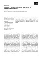
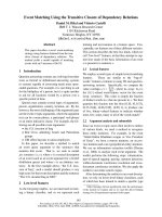
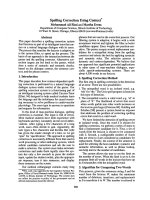
The Clarity Breast System
The Clarity System consists of two 3D-US devices, the US-
Sim™ and the US-Guide™, as represented in Figure 1.
The US-Sim resides in the CT-Simulation room, whereas
the U/S-Guide is in the treatment ro om; 3D-US images
are acquired by scanning the region of interest with an
ultrasound probe that has infrared reflective markers
affixed to its handle. The markers are tracked by an infra-
red camera to determine the position and orientation of
each ultrasound frame. The frames are then reconstructed
to form a 3D voxel dataset. These 3D-US images are cali-
brated to the room coordinate system of the correspond-
ing CT and treatment room to allow a direct comparison
of the reference 3D-US images at simulation to those
acquired in the treatment room. This set up allows the
same image modality to be used for the comparison. The
Clarity breast module uses a high frequency linear probe
(central frequency 8 MHz) which allows for a resolution
on the order of 0.2 mm.
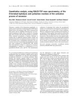
Ultrasound Scanning
The scanning technique requires a sweep over the area
of interest with negligible probe pressure through a
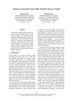
thick layer of high viscosity gel [18]. In addition, the
Ultrapath feature within Clarity illustrates the scanning
path of the probe used at the initial simulation as a
reference that facilitates reproducibility of image capture
on each treatment day. Figure 2.
CT/3DUS Simulation
The standard procedure for CT simulation was followed.
Patients were positioned supine with the ipsilateral arm
over head. For immobilization, alpha cradle and breast
board were used. Both the CT simulation and 3D-US
images were acquired in rapid succession. The CT and
3D-US images were implicitly registered since they
shared the same coordinate system through calibration.
The registration of the fused CT and 3D-US images was
verified qualitatively.
Treatment planning
CT images acquired with 2.5 mm slices from the neck to
beyond the inframammary fold were used for defining
the various target structures. We use the following defini-
tions in reporting this study: The breast planning volume
Figure 1 C larity system: (a) US-Sim in CT room, and (b) US-
Guide in treatment room.
Chadha et al. Radiation Oncology 2011, 6:45
/>Page 2 of 11
was defined as the volume of the palpable breast identi-
fied on CT. The lumpectomy cavity contoured only on
the images from CT simulation identified by bot h clips
and seroma defined the gross target volume (GTV). The
boost planning target volume (PTV) was defined as the
GTV (lumpectomy cav ity) with a 1.5 to 2 cm margin
except when there is proximity to overlying skin and
underlying chest wall. The seroma contoured on the
3DUS image obtained at simulation served as the refer-
ence volume (RV) for IGRT. The seroma contoured on
3D-US images acquired on the treatment table during
daily therapy is defined as the guidance volume (GV) for
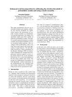
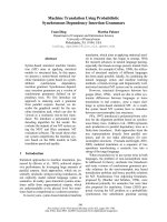
IGRT. An example of a fused image dataset with both
GTV and RV is shown in Figure 3.
For this study, we followed the standard procedure of
using only CT simulation images for contouring target
volume and normal anatomy. The 3D-US data w as not
used to modify the contours. Whole-breast radiation
therapy was planned using field-in-field forward-plan-
ning intensity modulated radiation therapy technique.
For the boost plan the choice of using photons or elec-
trons was based on the beam characteristic that deliv-
ered an optimal coverage of the boost target volume.
The information of the approved treat ment plan is o-
center, radiation fields and the CT images were
imported into the Clarity Workstation through DICOM
transfer. This information was linked to the RV on the
3D-US images from simulation.
Data acquisition and data analysis
The alignment software in the Clarity system is different
for photon and electron boost patients, and thus the
technique for da ta acquisition differed depending on the
choice of beam for boost treatments.
For photon boost, after the patient was positioned in
the therapy room 3D-US images were acquired just
prior to treatment. The seroma cavity as seen on the
3D-US was contoured using semi-automatic tools on
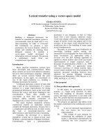
theUS-GuidetodefinetheGVforIGRT.TheGVwas
then visualized on the monitor in relation to the RV
and PTV, as sho wn in Figure 4. Calcul ation of a couch
shift required for either aligning the GV to the RV and/
or ensuring that the GV falls completely within the PTV
of the treatment plan is performed. The couch shifts
required for aligning could then be executed by affixing
the Clarity couch positioning indicator (CPI), which is
tracked by the optical camera in the room coordinate
system, to the treatment couc h. These shifts were not
executed in this study.
For electron boosts, patient were aligned according to
the instructions of the plan set up maintaining the
couch and gantry at zero degrees. The 3D-US image
Figure 2 The Clarity Ultrapath feature, illustrating the scanning
path of the probe used at the initial simulation.
Figure 3 Axial view of a fused CT/3D-US dataset .The
ultrasound-based reference volume (RV) is in red, the CT-based GTV
in yellow, and the PTV in blue.
Chadha et al. Radiation Oncology 2011, 6:45
/>Page 3 of 11
was acquired. The seroma cavity as seen on this image
was contoured using semi-automatic tools on the US-
Guide to define the GV. The Clarity digitizer, a ball-
point tip tool with infrared markers, was used to digitize
the scar. This provi ded both internal and external anat -
omy in the electron beam’ s eye view (EBEV). The
Clarity couch positioning indicator (CPI) wa s the n
affixed to the treatment couch, and the couch was
moved and rotated into final treatment position. The
CPI tracked these couch motions, and gantry angle
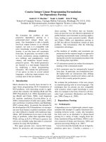
changes were typed in manually. As shown in Figure 5,
the Clarity screen showed the alignment of the GV and
scar relative to the cut-out in real-time as the patient
was brought into treatment position, as well as the over-
lay of the RV reference contour for comparison.
The registration of the fused CT and 3D-US images
was verified qualitatively for cavity visibility on both. The
overlay of GTV on CT simulation and RV on 3D-US
obtained at simulation provided an opportunity to corre-
lating observations between imaging modalities. Further,
comparing the RV from the 3D-US obtained at simula-
tion to the GV from the 3D-US obtained at the first
treatment fraction provided an opportunity to evaluate
the percent change in volume of the seroma cavity.
For phot on boosts, we evaluated two potential types of
shifts between the GV and RV structures: a) the center-
to-center shift between the GV and RV, which would
center the cavity at time of treatment; and (b) the center-
to-center shift between the GV obtained at the time of
the first fraction (which was associated with verification
of patient position using port films) with the GV from all
remaining treatment fractions. This second method
excludes the reference of shifts to simulation so as to
minimize the confounding variable of change in size of
the seroma between simulation and start of radiation
therapy.
For electron boosts, the cen ter-to-center displacement
between the GV and RV in the EBEV plane was calcu-
lated for each fraction. These were co mpared to the dis-
tance of the cavity to the electron cut-out, minus a
margin to account for the known electron dose fall-off
for the given electron energy at depth. The displace-
ments were also calculated between the center of the
GV for subsequent fractions to the GV obtained at the
first fraction of boost treatment.
Results
Ultrasound IGRT depends on presence of a seroma.
Among the screened patients we observed presence of
seroma in 93% of cases. Among the 20 patients with ser-
oma enrolled in the study, data on 127 fractions was col-
lected. Data on 14 total fracti ons, of which 7 were from a
single p atient, were not evaluable due to systematic
errors made while capturing the data. This represented a
learning curve for our team a nd an overall QA compli-
ance of 89% of all fractions studied. Data on the remain-
ing 113 fractions (75 photon boost and 38 electron
boost) on 19 patients is reported.
Figure 4 The RV (green), the GV (red), and the PTV (white). The
change between the GV and RV indicates the change in seroma
positioning between simulation and treatment.
Figure 5 The GV (red) posit ion versus RV (green) contour of
electron boost in the EBEV relative to the cut-out (blue).
Magenta is the digitized scar.
Chadha et al. Radiation Oncology 2011, 6:45
/>Page 4 of 11
Cavity volumes
The GTV-CT t arget volume in most cases was defined
by surgical clips and seroma cavity identified on the CT
image, Figure 6. The relation ship between the GTV-CT
and RV on US images showed that RV was smaller than
the GTV-CT o n average b y 38% (SD 23%). Further, it
was also noted that the RV-US was not always in the
geometric center of the GTV-CT, Figure 7.
The average decrease in the RV during the time lapse
between the simulation and the first boost treatment
was noted to be 49% (SD 31%). The average time inter -
val between the simulation and treatment session was
42 (SD 44) days. Volume change over elapsed time is
shown in Figure 8.
Photon boost fractions
Histograms of the IGRT shift (center of the GV to cen-
ter of RV) are shown in Figure 9. The average radial
shift was 1.1 ± 0.5 cm. Table 1 . However, because we
had also observed change in cavity volume between
simulation and the first boost fraction, the magnitude of
the shift could not entirely be attributed to variation in
set up and motion of cavity during daily therapy. In
order to exclude the effect of c hange in seroma volume
used for image guidance during the boost phase, we
evaluated the shifts of the GV between the first boost
fraction and GV for the subsequent boost fractions. His-
tograms for these shifts excluding the RV are shown in
Figure 10. The average radial shift was 0.8 ± 0.4 cm.
Table 2.
Electron boost fractions
For patients receiving electron boosts, using the RV
from simulation US as reference to the GV during
boost fractions we observed an average shift of 1.0 ±
0.5 cm, Table 3. Comparing GV from the first treat-
ment fraction as reference for all subsequent fractions,
the average shift w as 0.8 ± 0.4 cm. The results of GV
displacements in x and y collimator directions within
1 cm radius with reference to RV are projected in
Figure 11a. This combined total EBEV shift is 1.0 ±
0.5 cm.
Figure 6 CT image with clips, co-registered with US in axial, coronal and sagittal views. CT cavity (GTV) is in yellow, US seroma (RV) is in
red, and blue represents PTV. In this case the US provides additional information for seroma definition.
Chadha et al. Radiation Oncology 2011, 6:45
/>Page 5 of 11
The results for the cavity displacements between the
GV of the first and subsequent treatment fractions are
shown in Figure 11b. Smaller, yet clinically significant,
IGRT shifts were identified with an average total shift of
0.8 ± 0.4 cm. Average and standard deviations of shifts
in each direction are summarized in Table 4. We
observed in 52% of fractions shifts > 1.0 cm using the
RV from simulation, which decreased to 36% when the
first fraction GV was used as reference.
Discussion
During the course of radiotherapy, there may be inter-
fractional changes in the cavity position due to set-up,
breast mobility, chest wall motion, and changes in cavity
over time due to healing. In order to visualize the lum-
pectomy cavity for interfractional breast IGRT, some
reports have utilized surface cameras for localization
[19], which assumes that the cavity remains in a fixed
position relative to the skin surface. X-ray modalities
such as portal imaging or CBCT have limited or no
Figure 7 US and CT image co-registration in axial, sagittal and coronal views. The CT cavity (GTV) is in blue, US seroma (RV) in green, and
the blue represents PTV. The RV is not always in the geometric center of the GTV.
0 20 40 60 80 100 120 140 160 180 200
-20
0
20
40
60
80
100
Photon Boost Patients
Electron Boost Patients
%
U
/S
Volume
C
hange
Time between Simulation and Treatment
(
da
y
s
)
Figure 8 Volume of seroma contoured on 3D-US at time of
simulation (RV) and first RT fraction (SGV), for (a) photon
boost, (b) electron boost. Graph (c) plots percentage volume
change over time between imaging sessions.
Chadha et al. Radiation Oncology 2011, 6:45
/>Page 6 of 11
ability to directly visualize the cavity, but can use surro-
gates such as surgic al clips for this purpose [9,20,21].
Application of these technologies results in additional
radiation exposure. Furthermore, there are conflicting
results in the literature raising questions on the reliability
of clips. Weed et al [9] studied the use of clips for IGRT
and found that intrafractional cavity motion was clinically
significant; Kim et al [20] suggest that clips are not an
ideal surrogate for cavity localization. 3DUS gives a direct
soft-tissue visualization of the cavity the image for 3DUS
is target specific for visualization of the lumpectomy cav-
ity and therefore optimal for IGRT in breast cancer.
Furthermore, US technology is not associated with addi-
tional radiation exposure especially a consideration when
daily imaging is required [22,23].
This study provided an opportunity to evaluate how
best to apply 3D-US fo r IGRT. For an ultrasound image
to be a specific and sensitive tool, visibility of the ser-
oma is critical. In our study group, a 93% visibility of
seroma makes the application of 3DUS guidance a prac-
tical tool for IGRT in breast cancer. These observations
are comparable to reports by Wong et al and Berrang et
al [10,11,18]. Although CT/3DUS fused datasets were
not used for contouring GTV in this study, visual
inspection of the fusion showed complementary infor-
mation as suggested by others [18]. Further, we
observed that the RV on US was always smaller and not
always in the geometric center of the GTV-CT. In
Figure 7, for example the US image illustrates seroma
cavity protruding outside the GTV-CT contour,
-3 -2 -1 0 1 2 3
0
5
10
15
20
25
30
Frequency
Ant/Post Displacement (cm)
-3 -2 -1 0 1 2 3
0
5
10
15
20
25
30
Frequency
Sup/Inf Displacement (cm)
-3 -2 -1 0 1 2 3
0
5
10
15
20
25
30
Frequency
RT/LT Displacement (cm)
0.0 0.5 1.0 1.5 2.0 2.5 3.
0
0
5
10
15
20
25
30
Frequency
Radial Displacement (cm)
Figure 9 Distribution of cavity shifts for photon boosts using (a) Ant/Post, (b) Sup/Inf, (c) Right/Left, (d) radial directions from the RV
on the simulation US.
Table 1 Average and standard deviation of photon boost cavity displacements in the three orthogonal directions, and
total radial displacement
Displacement R/L (cm) S/I (cm) A/P (cm) Radial (cm)
Simulation US reference 0.2 ± 0.8 0.1 ± 0.7 0.2 ± 0.6 1.1 ± 0.5
1st Treatment Fraction US Reference 0.2 ± 0.5 -0.1 ± 0.5 0.1 ± 0.6 0.8 ± 0.4
Results are shown using both the simulation and first treatment fraction scans as the RV.
Chadha et al. Radiation Oncology 2011, 6:45
/>Page 7 of 11
-3 -2 -1 0 1 2 3
0
5
10
15
20
25
30
Frequency
Ant/Post Displacement (cm)
-3 -2 -1 0 1 2 3
0
5
10
15
20
25
30
Frequency
Sup/Inf Displacement (cm)
-3 -2 -1 0 1 2 3
0
5
10
15
20
25
30
Frequency
RT/LT Displacement (cm)
0.0 0.5 1.0 1.5 2.0 2.5 3.
0
0
5
10
15
20
25
30
Frequency
Radial Displacement (cm)
Figure 10 Distribution of cavity shifts for photon boost in (a) Ant/Post, (b) Sup/Inf, (c) Right/Left and (d) radial directions, using GV
from the first RT fraction US.
Table 2 Results of photon boost cavity displacements using both the simulation and first treatment fraction scans as
the RV
Simulation US Reference 1st Treatment Fraction US reference
Radial Displacement (cm) # fractions Percentage of fractions # fractions Percentage of fractions
> 1.5 16 22% 3 5%
> 1.0 36 50% 15 24%
> 0.5 65 90% 46 73%
Table 3 Average and standard deviation of cavity displacements for e- boost in the x and y-collimator direction, and
radial displacements, within the EBEV
Displacement x (cm) y (cm) Total EBEV (cm)
Simulation US reference -0.2 ± 1.0 0.4 ± 0.6 1.0 ± 0.5
1st Treatment Fraction US Reference -0.1 ± 0.7 0.2 ± 0.5 0.8 ± 0.4
Results are shown using both the simulation and first treatment fraction scans as the RV.
Table 4 Cavity displacements for e-boost
Simulation US Reference 1st Treatment Fraction US reference
EBEV Displacement (cm) # fractions Percentage of fractions # fractions Percentage of fractions
> 1.5 8 26% 1 4%
> 1.0 16 52% 9 36%
> 0.5 26 84% 17 71%
Results are shown using both the simulation and first treatment fraction scans as the RV.
Chadha et al. Radiation Oncology 2011, 6:45
/>Page 8 of 11
suggesting that fused dataset may enhance the accuracy
for target delineation.
In this study, we exclusively contoured the seroma
cavity on the 3D-US since our primary intent was to use
the structure as a landmark for IGRT positioning pur-
poses rather than treatment planning. We found that
the seroma outlines gave the clearest and most reprodu-
cible edges to calculate daily IGRT shifts from simula-
tion and treatment 3D-US images. This method
effectively uses the seroma cavity imaged with 3D-US
more as a fiducial guide for the target in performing
IGRT rather than representing the target itself.
Our observations also helped define the importance of
the timeline in which the images for IGRT are obtained.
In this study, we acquired simulation data for the boost
IGRT treatments only once using our standard practice
of dosimetry planning on the one initial CT and 3D-US
simulation. We observed a reduction of the cavity volume
on 3DUS of 49% (SD 31) between the simulation and the
first boost fraction. Further, this raises a question on how
to accurately align the GV acquired at the time of treat-
ment to the RV from simulation for IGRT. Intuitively,
shifting the patient to center the GV on the RV may not
ensure accurate coverage particularly if there has been
asymmetric cavity shrinking. To circumve nt this pro-
blem, we recommend the implementation of CT/3D-US
simulation session just prior to the treatments that will
use IGRT. Based o n our observations w e suggest that a
second CT and 3D-US simulation should be performed
just prior to starting the boost. This would help eliminate
thevariableofchangeincavityvolumeandimprovethe
accuracy of IGRT. Although a second CT/3D-US was not
performed in this initial study, we simulated its effect by
using the first boost fraction contour as the RV, and still
observed shifts required to overlay the seroma volume
during daily positioning. This observation suggests the
potential value for IGRT in treatment of breast cancer.
Electron boosts, although physically similar in terms of
interfractional cavity changes as noted by the similar
shift results found in this study, are inherently different
due to the nature of electron treatment setups and elec-
tron dose deposition . Shifts were compared to the edges
of the electron cut-out, but electron doses can taper in
significantly from these edges, depen ding on the elec-
tron energy. We primarily analyzed the displacements in
the plane of the EBEV for this purpose. The average
electron penumbra requires the target to be positioned
within 1 cm to avoid target misses. Using the simulation
RV as referenc e, 52% of fractions would have fallen out-
side of this range. Again, similar to the photon data
review to simulate planning images acquired just prior
to the boost, we compared the shifts using the GV from
the first treatment fraction as reference for all subse-
quent fractions of GV. We still noted that 36% would
have fallen outside of this range. This suggests that
IGRT corrections would be be neficial for electron boost
targeting with currently used cutout margins. IGRT may
also allow use of more conformal fields as the physical
margin for day-to-day positioning can be eliminated and
smaller volumes are associated with better tolerance and
lesser toxicity. It should be noted that with electron
boost IGRT, an additional concern is maintaining the
correct source-to-surface distance, as well as targeting
A.
B
Figure 11 Scatter plot of electron boost cavity displacements
within the EBEV: (a) using RV from simulation US, (b) using GV
from the first RT fraction US.
Chadha et al. Radiation Oncology 2011, 6:45
/>Page 9 of 11
surface landmarks such as the surgical scar. This can be
accomplished with the Clarity system since landmarks
are digitized with the pointer tool, and targeting adjust-
ments can be accomplished while maintaining the pre-
scribed SSD.
The dose response relationship in breast cancer has
been illustrated through the boost vs. no boost rando-
mized trial [24], and is known to significantly decrease
the risk of local recurrence [25-27]. As demons trat ed in
this preliminary study, IGRT in breast cancer therapy
has the potential for improving the accuracy of targeting
the lumpectomy site. IGRT may also significantly
improve the delivery of conformal partial breast irradia-
tion, a treatment strategy currently being studied as an
alternative to whole breast irradiation [28], as well as
whole breast fractions for patients with cavities close to
the tangent field edges.
Conclusion
Our experience suggests that the Clarity Breast System
can be used without significantly interfering with patient
flo w in a busy department. The presence of a seroma is
noted in a relatively high percentage of patients even
with long time intervals after the most recent surgery.
The Clarity Breast System can successfully locate the
seroma on a daily basis, without extra radiation expo-
sure. For more accurate target volume delineatio n, data
from both US and CT images should be used when con-
touring. The daily set-up isocenter shifts we observed
suggests an opportunity for improving precision of RT
dose targeting with IGRT. In order to use the seroma
cavity for IGRT, the time i nterval between simulation
and treatment should be kept at a minimum. Future
work will include a second CT/3D-US simulation just
prior to initiating IGRT treatment. Further study is
needed to establish the optimal protocol for clinical
application of 3D-US IGRT including defining the ideal
times for image acquisition, optimal volume used for
image guidance, and establish the clinical significance of
improved targeting by correcting the interfractional
shifts.
Authors’ contributions
MC, LH conceived of the study, and participated in its design and
coordination. AY participated in the coordination and statistical analysis. CG
and RM performed data acquisition on all images and contributed to the
statistical analysis. All authors have approved the final manuscript.
Conflicts of Interests
The authors have no conflict of interest
Received: 21 December 2010 Accepted: 9 May 2011
Published: 9 May 2011
References
1. Lattanzi J, McNeely S, Hanlon A, et al: Daily CT localization for correcting
portal errors in the treatment of prostate cancer. Int J Radiat Oncol Biol
Phys 1998, 41:1079-1086.
2. Poulsen PR, Muren LP, Hoyer M: Residual set-up errors and margins in on-
line image-guided prostate localization in radiotherapy. Radiother Oncol
2007, 85:201-206.
3. Sorcini B, Tilikidis A: Clinical application of image-guided radiotherapy,
IGRT (on the Varian OBI platform). Cancer Radiother 2006, 10:252-257.
4. Willoughby TR, Kupelian PA, Pouliot J, et al: Target localization and real-
time tracking using the Calypso 4D localization system in patients with
localized prostate cancer. Int J Radiat Oncol Biol Phys 2006, 65:528-534.
5. Kupelian P, Willoughby T, Mahadevan A, et al: Multi-institutional clinical
experience with the Calypso System in localization and continuous, real-
time monitoring of the prostate gland during external radiotherapy. Int J
Radiat Oncol Biol Phys 2007, 67:1088-1098.
6. Lattanzi J, McNeeley S, Donnelly S, et al: Ultrasound-based stereotactic
guidance in prostate cancer–quantification of organ motion and set-up
errors in external beam radiation therapy. Comput Aided Surg 2000,
5:289-295.
7. Tome WA, Meeks SL, Orton N, et al: Commissioning and quality assurance
of an optically guided three-dimensional ultrasound target localization
system for radiotherapy. Med Phys 2002, 29:1781-1788.
8. Cury FL, Shenouda G, Souhami L, et al: Ultrasound-based image guided
radiotherapy for prostate cancer: comparison of cross-modality and
intramodality methods for daily localization during external beam
radiotherapy. Int J Radiat Oncol Biol Phys 2006, 66:1562-1567.
9. Weed DW, Yan D, Martinez AA, et al: The validity of surgical clips as a
radiographic surrogate for the lumpectomy cavity in image-guided
accelerated partial breast irradiation. Int J Radiat Oncol Biol Phys 2004,
60:484-492.
10. Wong P, Heimann R, Hard D, et al: A multi-institutional comparison study
evaluating the use of 3D-ultrasound for defining the breast tumor bed
for IGRT in chemotherapy versus non-chemotherapy patients. Int J
Radiat Oncol Biol Phys 2008, 72:S179-180.
11. Wong P, Audet V, Lachaine M, et al: Validation of an intramodality 3D
ultrasound system for breast IGRT. Proceedings of the American Radium
Society
2008.
12.
Powell SN, Doppke KP, Chen GT, et al: Set-up uncertainty in accelerated
partial-breast irradiation using 3D- conformal external beam
radiotherapy: A companion study to a prospective phase I ongoing trial.
Int J Radiat Oncol Biol Phys 2004, 60:S400-S401.
13. Bedwinek J: Breast conserving surgery and irradiation: the importance of
demarcating the excision cavity with surgical clips. Int J Radiat Oncol Biol
Phys 1993, 26:675-679.
14. Machtay M, Lanciano R, Hoffman J, et al: Inaccuracies in using the
lumpectomy scar for planning electron boosts in primary breast
carcinoma. Int J Radiat Oncol Biol Phys 1994, 30:43-48.
15. Oh KS, Kong FM, Griffith KA, et al: Planning the breast tumor bed boost:
changes in the excision cavity volume and surgical scar location after
breast-conserving surgery and whole-breast irradiation. Int J Radiat Oncol
Biol Phys 2006, 66:680-686.
16. Benda RK, Yasuda G, Sethi A, et al: Breast boost: are we missing the
target? Cancer 2003, 97:905-909.
17. Ringash J, Whelan T, Elliott E, et al: Accuracy of ultrasound in localization
of breast boost field. Radiother Oncol 2004, 72:61-66.
18. Berrang TS, Truong PT, Popescu C, et al: 3D ultrasound can contribute to
planning CT to define the target for partial breast radiotherapy. Int J
Radiat Oncol Biol Phys 2009, 73:375-383.
19. Bert C, Metheany KG, Doppke KP, et al: Clinical experience with a 3D
surface patient setup system for alignment of partial-breast irradiation
patients. Int J Radiat Oncol Biol Phys 2006, 64:1265-1274.
20. Kim L, Vicini F, Yan D: Clinically achievable accuracy of online localization
of the lumpectomy cavity using surgical clips [virtual poster]. 2005
[ = 000109)], 2005
ASTRO Annual Meeting Abstracts and Virtual Posters.
21. Hasan Y, Kim L, Weed DW, et al: Image Guidance in External Beam
Accelerated Partial Breast Irradiation: Comparison of Surrogates for the
Lumpectomy Cavity. Int J Radiat Oncol Biol Phys 2005, 63:S138.
Chadha et al. Radiation Oncology 2011, 6:45
/>Page 10 of 11
22. Cash CJ, Coles CE, Treece GM, et al: Breast cancers: noninvasive method
of preoperative localization with three-dimensional US and surface
contour mapping. Radiology 2007, 245:556-566.
23. Coles CE, Cash CJ, Treece GM, et al: High definition three-dimensional
ultrasound to localise the tumour bed: a breast radiotherapy planning
study. Radiother Oncol 2007, 84:233-241.
24. Vrieling C, Collette L, Fourquet A, et al: The influence of the boost in
breast-conserving therapy on cosmetic outcome in the EORTC “boost
versus no boost” trial. EORTC Radiotherapy and Breast Cancer
Cooperative Groups. European Organization for Research and Treatment
of Cancer. Int J Radiat Oncol Biol Phys 1999, 45:677-685.
25. Fisher B, Anderson S, Redmond CK, et al: Reanalysis and results after 12
years of follow-up in a randomized clinical trial comparing total
mastectomy with lumpectomy with or without irradiation in the
treatment of breast cancer. N Engl J Med 1995, 333:1456-1461.
26. Veronesi U, Banfi A, Salvadori B, et al: Breast conservation is the treatment
of choice in small breast cancer: long-term results of a randomized trial.
Eur J Cancer 1990, 26:668-670.
27. Bartelink H, Horiot JC, Poortmans PM, et al: Impact of a higher radiation
dose on local control and survival in breast-conserving therapy of early
breast cancer: 10-year results of the randomized boost versus no boost
EORTC 22881-10882 trial. J Clin Oncol 2007, 25:3259-3265.
28. NSABP B-39, RTOG 0413: A Randomized Phase III Study of conventional
whole breast irradiation versus partial breast irradiation for women with
stage 0, I, or II breast cancer. Clin Adv Hematol Oncol 2006, 4:719-721.
doi:10.1186/1748-717X-6-45
Cite this article as: Chadha et al.: Image guidance using 3D-ultrasound
(3D-US) for daily positioning of lumpectomy cavity for boost irradiation.
Radiation Oncology 2011 6:45.
Submit your next manuscript to BioMed Central
and take full advantage of:
• Convenient online submission
• Thorough peer review
• No space constraints or color figure charges
• Immediate publication on acceptance
• Inclusion in PubMed, CAS, Scopus and Google Scholar
• Research which is freely available for redistribution
Submit your manuscript at
www.biomedcentral.com/submit
Chadha et al. Radiation Oncology 2011, 6:45
/>Page 11 of 11