Báo cáo khoa học: " Eight years of IMRT quality assurance with ionization chambers and film dosimetry: experience of the montpellier comprehensive cancer center" potx
Bạn đang xem bản rút gọn của tài liệu. Xem và tải ngay bản đầy đủ của tài liệu tại đây (379.92 KB, 11 trang )
MET H O D O LO G Y Open Access
Eight years of IMRT quality assurance with
ionization chambers and film dosimetry:
experience of the montpellier comprehensive
cancer center
Pascal Fenoglietto
1*
, Benoit Laliberté
2
, Norbert Aillères
1
, Olivier Riou
1
, Jean-Bernard Dubois
1
and David Azria
1
Abstract
Background: To present the results of quality assuran ce (QA) in IMRT of film dosimetry and ionization chambers
measurements with an eight year follo w-up.
Methods: All treatment plans were validated under the linear accelerator by absolute and relative measures
obtained with ionization chambers (IC) and with XomatV and EDR2 films (Kodak).
Results: The average difference between IC measured and computed dose at isocenter with the gantry angle of 0°
was 0.07 ± 1.22% (average ± 1 SD) for 2316 prostate, 1.33 ± 3.22% for 808 head and neck (h&n), and 0.37 ± 0.62%
for 108 measurements of prostate bed fields. Pelvic treatment showed differences of 0.49 ± 1.86% in 26 fields for
prostate cases and 2.07 ± 2.83% in 109 fields of anal canal.
Composite measurement at isocenter for each patient showed an average difference with computed dose of 0.05
± 0.87% for 386 prostate, 1.49 ± 1.86% for 158 h&n, 0.37 ± 0.34% for 23 prostate bed, 0.80 ± 0.28% for 4 pelvis,
and 2.31 ± 0.56% for 17 anal canal cases. On the first 250 h&n analyzed by film in absolute dose, the average of
the points crossing a gamma index 3% and 3 mm was 93%. This value reached 99% for the prostate fields.
Conclusion: More than 3500 beams were found to be within the limits defined as validated for treatment
between 2001 and 2008.
Background
Intensity modulated radiotherapy (IMRT) was intro-
duced in France in the early years of this century. The
evolution of computing, with the ability to support new
algorithms, and the implementation of multileaf collima-
tors (MLC), made the development of this technique
possible. Our Cen ter was one of the first in France to
routinely treat patients using IMRT in 2001, thus find-
ing an efficient method of treatment delivery quality
assurance (QA) was a challenge. At the beginning, no
special system was developed for IMRT quality assur-
ance so that we had t o use ionization chambers and
film dosimetry to perform our measurements.
Since 2001, over 1000 patients with prostate, head and
neck, and anal canal carcinoma have been treated with
IMRT at the Comprehensive Cancer Center of Montpel-
lier in France. For all of them and before the first day of
treatment, we have checked the dose computed by the
treatment planning system (TPS) with measurements
under the linear accelerator. At our institution, a single
phase IMRT has been delivered for all treatments except
pelvic cases [1]. Conventional treatment often required
multiple portals and sequential field reductions. We
hypothesized that a single phase treatment would pro-
vide the p otential to reduce workload and improve
radiotherapy delivery efficiency.
The number of patients who could benefit from IMRT
increased dramatically as we improved our technique
over the years, but conventional QA limited its wide-
spread use because of the time needed for verification
* Correspondence:
1
Département de Cancérologie Radiothérapie et de Radiophysique, CRLC Val
d’Aurelle-Paul Lamarque, Montpellier, France
Full list of author information is available at the end of the article
Fenoglietto et al. Radiation Oncology 2011, 6:85
/>© 2011 Fenogli etto et al; licensee BioMed Central Ltd. Th is is an Open Acce ss article distributed under the terms of the Creative
Commons Attribution License ( .0), which permits unrestricted use, distribut ion, and
reprodu ction in any medium, provided the original work is properly cited.
and validation of the predicted fields [2]. Indeed, clinical
implementation of IMRT has been shown to be a com-
plex process [3-8].
Every center planning to introduce this technique
should be a ware of the importance of such a program
and allocate adequate resources to su pport it. Staff time
has previously been shown to be greater than with con-
ventional techniques [9].
As IMRT was becoming globally available, companies
specialized in ra diation measurements developed de di-
cated products for IMRT dosimetry, and in the last few
years, electronic portal imagers have allowed the acqui-
sition of dose produced by modulated beams and the
comparison between measurement and predicted dose
[10]. Further developments to reduce the burden of
IMRT fields QA i ncluding val idated calculation systems
for the independent check of monitor units [11].
However, new technologies reducing QA time and
workload should always hang in the balance with more
cumbersome but reliable evidence-based methods [12].
Changing a technique that has been employed for a
long time for a new one is not ea sily done without los-
ing known bearings. In addition, we are now in the pro-
cess of upgrading to the newer QA methods by
verifying all patients plans with both techniques. A high
geometric and dosimetric accuracy is required for
advanced techniques, and the verification of IMRT dose
dis tribution is a prerequisite for safe and efficient del iv-
ery[13].Atthispoint,thereisnogoldstandardtoset
the tolerance of an IMRT plan validation, even though
external audits are organized by institutions like Interna-
tional Atomic Energy Agency (IAEA) or European
Society for Therapeutic Radiology and Oncology
(ESTRO) for conventional QA [14,15] or IMRT tests
plansonphantoms[16].ThequestionofIMRTQAis
still a burning subject and a s mentioned by Palta et al.
[17]. Each facility offering IMRT have therefore to
develop its own guidelines and criteria for the accep-
tance of IMRT QA planning and delivery systems [17].
We present here the results obtained with film and ioni-
zation chambers used during the last 8 years for dosi-
metry of IMRT fields.
Methods
Treatment planning and delivery by IMRT
Treatment plans were generated using commercial soft-
ware. First studies were initially made on the Cadplan
Treatment Planning System (Varian, Palo Alto, CA) in
2000, and then with Eclipse, Helios, version 7.2.34, in
2003. Three hundred and twenty segments were used to
sample the sliding window delivery in the Eclipse calcu-
lation. All the plans were calculated without heterogene-
ity correction using a 2.5 mm dose matrix. Two linear
accelerators (Varian Clinac 21 EX linear accelerator,
Varian, Palo Alto, CA) were used for the t reatment
delivery using “ sliding- window” IMRT technique with
multileaf collimator (MLC Millenium 120, Varian, P alo
Alto, CA). Sharing the same MLC leakage transmissi on,
the calibration of the dosimetric leaf gap was adjusted
to obtain less than 0.5% difference for the same plan
delivered on the two different machines. Data were
transferred from t he TPS to the linear accelerator by a
French record and verify system: DIC ("Dossier Informa-
tisé en Cancérologie”, Sigma Micro, Toulouse, France).
Quality Assurance
Aft er the treatment validation on the TPS by the physi-
cian, a QA plan was created in the system, copying all
the beams included in the treatment plan on a dedicated
phantom (universal IMRT phantom, PTW, Freiburg,
Germany) previously scanned at our institution. All the
geometry paramete rs could be changed but the number
of monitor unit and the MLC sequence were exactly the
same as for the patient plan. A specific Excel sheet was
created to coll ect the information concerning the verifi-
cation plan.
Ionization chamber measurements
A verification plan of each field (with the gantry, table,
and collimator rotations set to 0°) in the universal
IMRT phantom (PTW, Freiburg, Germany) was gener-
ated in the TPS for all patients and values to specific
points (holes for chambers positioning in the phantom
at 6 cm depth) were considered. These points were not
specially chosen in a high dose or low gradient area but
werefixedbythephantomgeometry.Theaxisdosein
phantom at depth of 6 cm was measured under the
accelerator using an ionization chamber with a nomi nal
sensitive v olume of 0.125 cc (PTW 31010). This detec-
tor was chosen because the configuration of the dose
volume optimizer (DVO) algorithm in Eclipse was made
with measurements done with this de tector, even if its
spatial resolution was not so small. At our department,
a special interest focused on the way to configure the
TPS for IMRT planning using different detectors and
the influence on the fluency map created by the system.
Different detectors with a smallest spatial resolution
were used to commission IMRT (diamond chambers,
diodes) but we finally d ecided to use the same detector
for IMRT configuration as for the global commissioning
of the linear accelerator. Other measurements for points
at 2 a nd 4 cm lateral to the central axis could be also
acqu ired. Nearly 500 prostat e cancer patients were tre a-
ted by IMRT between 2001 and 2008. All of them were
treated using 6 beams (60°, 95°, 130°, 230°, 265° and
300°) and a high energy of 18 MV. For pelvic irradiation,
such as anal canal or high-risk prostate cancer, split
fields were used due to the large size of the target
Fenoglietto et al. Radiation Oncology 2011, 6:85
/>Page 2 of 11
volume. Beam co nfiguration was a 7-field template at
the following gantry angles (0°, 45°, 110°, 165°, 195°,
250° and 325°). Methodology for QA was the same as
for the non-split fields with measurements consisting of
the sum of the different subfields for the same gantry
rotation. Energy of 6 MV and 5 beams (0°, 70°, 140°,
210°, and 290°) are used with a non-split technique for
the majority of the head and neck patients. For more
simplicity and to spare time, the QA measurements are
performed with a gantry position of 0° in a flat phantom
(universal IMRT phantom, PTW, Freiburg, Germany). It
is known that this method neglected the effect of gravity
on the mechanical parts (gantry, MLC carriage and
leaves) during our procedure. To quantify the gap that
could be caused by this effect, we also irradiated the
same plans in a cylindrical phantom (head and neck
IMRT phantom, PTW, Freiburg) with the real gantry
angle as for the treatment of the first 36 patients.
Film dosimetry
To verify relative and/or absolute distribution in two
dimensions and not simply at specific points, we decided
to use film dosimetry. The film was placed for each field
at 5 cm depth in the flat phantom and perpendicular to
the irradiation. During the f irst years, we used XOMAT
films (Eastman Kodak Co., Rochester, NY, USA) but the
response of this film was not linear with the dose deliv-
ered. We thus replaced it with EDR2 since the latter
wasabletohandleadoseofmorethan2Gywithout
any saturation effect [18]. A calibration curve was
plotted each time w ith a verification plan for a patient.
Films were developed in an automatic machine and digi-
tized with a Vidar VXR-12 digitizer (Vidar Systems Cor-
poration, Herndon, VA, USA)
The spatial resolution used to digitize the film was 75
dpi, which correspo nded to 2.95 pixels/mm. This was
not the highest resolution provided by the system but
was sufficient to compare with the calculation resolution
(0.338 pixels/mm c ompared to 2.5 pixels/mm). The
information was coded in 12 bits and no filtration was
used during the 10 ms of acqui sition. A study was d one
using different digitalization tables provided by the
Vidarsoftwaretoseewhichwerethemostusefulfor
routineuse.Wechosetolookatthreespecifictables:
linear, logarithmic, and PW5 (power 5)
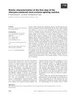
An analysis of optical density (OD) scales provid ed by
the Vidar VXR 12 was performed using these three dif-
ferent acquisition tables. A line crossing the different
readings of an OD scale increasing from 0 to 3.8 OD
was analyzed (Figure 1a). The electronic response of the
Vidar varied with the table used (log, linear, or PW5).
Logarithmic tables presented a more linear response of
the signal and showed more OD levels corresponding to
a higher dose. On the other hand, for low OD levels,
the other tables provided a larger difference of Vidar
readings for the same OD strip meaning that discrimi-
nation between two different levels was easier at smaller
doses. Finally, we decided t o use th e log table when we
verified a global plan that included the entire treatment
fields.
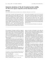
Initially, we tried to define a calibration curve to convert
the Vidar dose readings to the different acquisition table
used (Figure 1b). However, we realized that, due to day-
to-day variations, our film necessitated a calibration at
each treatment verification. A kind of “step wedge” film
with diff erent pred efined dose levels allowed us to create
these calibration curves. The result for XOMAT films
(Figure2a)andEDR2(Figure2b)showedthatitcorre-
sponded to a direct change of the slope of the curve [19].
Academic software developed by the MD Anderson
hospital (Doselab) was used to analyze films by profile
and isodose comparison. Since 2003, we have validated
the results using the gamma index [20] but we will switch
soon to radiochromic films for measurements [21].
Results
Ionization chamber
We present in this paper the results for the 386 first
patients corresponding to 2316 individual dose beams
measured at the isocenter with the gantry at 0°. The
average difference between measurements and predicted
TPS dose was 0.07 ± 1.22% (Me an ± 1SD) (Figure 3a).
Theseresultsaresimilartoastudyinwhich380pros-
tate fields were analyzed [22].
Consid ering the dose at isocenter for the entire trea t-
ment (sum of all the beams) and for each patient, the
measured dose was always within 3% of calculated dose
except for 3 cases (0.05 ± 0.87%) (Figure 4a). Since
2008, IMRT has become our standard treatment for
post-prostatectomy radiotherapy for which acceptable
concordance was also obtained between planned and
measured dose. The average difference was -0.37 ±
0.62% for the 108 beams and -0.80 ± 0.28% for the indi-
vidual 23 patients.
For pelvic irradiation, the results for beam by beam
analysis were -0.49 ± 1,86% and 2.07 ± 2.83% for 26
high risk prostate cancer and 109 anal canal beams,
respectively. Distribution of the readings was not the
same even though the energy and the beam angles were
identical. Indeed, the total delivered dose was infe rior
for the an al canal cases compared to the high-risk pros-
tate cancer cases (59.4 Gy vs 80 Gy ICRU) but the mod-
ulation factor was greater for anal cancer due to the
increased complexity re quired to reach the constraints.
This modulation factor could be interpreted as a new
metric for assessing IMRT modulation complexity as it
look at the number of MU delivered by Gy. The more
difficult is the plan, the smallest is the opening of the
Fenoglietto et al. Radiation Oncology 2011, 6:85
/>Page 3 of 11
0
10000
20000
30000
40000
50000
60000
70000
0 100 200 300 400 500 600 700 800
distance (pixels)
Vidar Unit (a u)
( a )
(
b
)
0
10000
20000
30000
40000
50000
60000
70000
0 0,5 1 1,5 2 2,5 3
Optical Density (OD)
Vidar Unit (au)
Figure 1 Vidar reading (ua) of an optical density wedge. (a) Reading of the OD step (b) Graph is plotted as a function of Optical Density for
different digitalization table provide by the Vidar system. (Dark value is for logarithmic acquisition table, grey for PW5, and the light grey for
linear table.)
Fenoglietto et al. Radiation Oncology 2011, 6:85
/>Page 4 of 11
sliding window and the number of MU necessary to
deliver the dose increase. The dose distributions in pros-
tate cases are more centered in the histogram than in
anal canal cancers and similar results for the patient
dose were found where discrepancies reached -0.80 ±
0.28% for 4 high-risk p rostate treatments and 2.31 ±
0.56% for 17 anal canal cases.
Head and neck treatments needed more modulation to
achieve goal constraints bringing complicated fluencies
that were more difficult to measure. Figure 3b shows that
xomat films
0
10000
20000
30000
40000
50000
60000
0 1020304050607080
dose (cGy)
vidar reading (ua)
( a )
EDR2 films
30000
40000
50000
0 1020304050607080
dose (cGy)
vidar reading (ua)
(
b
)
Figure 2 Vidar reading (ua) for dose calibration films performed before patients QA. XOMAT-V films (a) and EDR2 films (b).
Fenoglietto et al. Radiation Oncology 2011, 6:85
/>Page 5 of 11
the shape of the graph is fla tter for the 710 b eam-by-
beam control points of the 158 first patients (-1.33 ±
3.22%). Global measurements show more negative values
than in all the other cases treated by IMRT (-1.49 ±
1.86%) (Figure 4b). The results are shown in (Figure 5)
where striped bars represent measurements taken with
rotated gantry. We show ed that the global distribution
have the same appearance with a difference between cal-
culation and measurement of -0.70 ± 2.42% and -0.72 ±
3.20% for plan and rotated gantry studies, respectively.
( a )
(
b
)
0
10
20
30
40
50
60
70
80
90
-5 to -4
-4 to -3.5
-3.5 to -3
-3. to -2.5
-2.5 to -2
-2 to -1.5
-1.5 to -1
-1 to -0.5
-0.5 to -0
-0 to 0.5
0.5 to 1
1 to 1.5
1.5 to 2
2 to 2.5
2.5 to 3
3 to 3.5
3.5 to 4
4 to 5
dose difference between calculation and measurements (%)
number of fields
0
50
100
150
200
250
300
350
400
450
-4 to -3.5
-3.5 to -3
-3 to -2.5
-2.5 to -2
-2 to -1.5
-1.5 to -1
-1 to -0.5
-0.5 to 0
0 to 0.5
0.5 to 1
1 to 1.5
1.5 to 2
2 to 2.5
2.5 to 3
3 to 3.5
-3.5 to 4
dose difference between calculation and measurements (%)
numbers of fields
Figure 3 Dose difference between measured and calculated dose for beam by beam measurements.Resultsfor2319prostatefields(a)
and 808 head and neck fields (b).
Fenoglietto et al. Radiation Oncology 2011, 6:85
/>Page 6 of 11
( a )
(
b
)
-4
-3
-2
-1
0
1
2
3
0
25 50
75
100
125 150 175 200 225 250 275 300 325 350 375 400
Patients No
Difference between measured and calculated dose (%)
-4
-3
-2
-1
0
1
2
3
0 20 40 60 80 100 120 140 160
Patients No
Difference between measured and calculated dose (%)
Figure 4 Dose difference between measured and calculated dose for global patient verification. Results for 383 prostate cases (a) and
158 head and neck cases (b). Square dots represent verification with gantry angle at 0° and triangular dots with the gantry in the treatment
position.
Fenoglietto et al. Radiation Oncology 2011, 6:85
/>Page 7 of 11
Gamma index results
As both geometric and dosimetric accuracy are impor-
tant in IMRT, we decided to use the gamma (g)index
approach [23]. The dosimetric criteri on is a dose-differ-
ence represented as a percentage of the prescribed dose.
In the terminology of Low and Dempsey [23], the m ea-
sured dose distribution was taken as the reference and
the computed dose distribution was evaluated against it.
If g (i) < 1, the dose delivered at point i is considered to
be within the tolerance criteria and hence is accepted
with regards to the computed i.e. intended dose. It
should be noted that lower g-values are obtained by
considering the full three-dimension of the calculated
dose matrix and hence by incorporating dose variation
in the perpendicular direction to the film, making the
verification more realistic in case of longitudinal dose
gradients.
The Doselab software was used for treatment film ver-
ification. After the verification of the calibration by
applying the calibration curve to the calibration film
(step wedge) and the comparison with the Eclipse plan,
the calibration curve was applied to the patient films. By
doing this, an absolute dose validation was possible and
could be compared to IC measurements. For prostate
plans, the number of points passing the gamma index
was always superior to 99%. This result was in agree-
ment with chamber measurements and was mainly due
to the fact that the modulation of the beam for a pros-
tate plan generates a uniform dose distribution in the
centre of the beam which is a good condition for
measur ement (high dose, small gradient). Gamma histo-
grams were calculated on the film area defined by the
primary jaws. For head and neck treatments, the gamma
index was studied for two different couples of values. A
3% / 3 mm criterion represented our acceptance level.
We also analyzed the films with a 5% / 3 mm criterion
to compare our results with those published in the lit-
erature and be cause the acc eptance dose difference in
IC for film-by-film measurements was fixed at 5%. For
the 500 films studies, p ercentage of point reaching the
gamma agreement was 91.66 ± 9.62% and 97.68 ± 5.41%
for 3% / 3 mm and 5% / 3 mm, respectively (Figure 6a
and Figure 6b). Some points showed a gamma index
below 80% but the areas with bad results were located
out of the irradiation field and inside a low (transmis-
sion only) dose area. These results are comparable to
those published by De Martin et al. [24] where they
showed 95.3% and 87.6% points passing the acceptance
criterion of 4% / 3 mm for two therapy units and 57
head and neck patients. In their study, only points on
dose levels higher than 10% of the prescription dose
were studied allowing better results.
Discussion
IMRT requires quality assurance (QA) for each patient
before radiotherapy treatments but no gold standard is
defined for acceptance of the verification process. Wil-
cox et al. [25] presented QA results on a small study of
172 patients which correlated to our measurements. The
QA results are the sum of different processes in the
0
5
10
15
20
25
30
35
40
-5 T -4
-4 to 3
-3 to -2
-2 to -1
-1 to 0
0 to 1
1 to 2
2 to 3
3 to 4
4 to 5
dose difference between calculation and measurements (%)
number of fields
Figure 5 Dose difference between measured and calcula ted dose for beam by beam verification for head and neck cases.Thedash
bars represent acquisition realized with the gantry at the real treatment position and the full bars represent the values with the gantry at 0° for
the same patients.
Fenoglietto et al. Radiation Oncology 2011, 6:85
/>Page 8 of 11
chain of events leading to the treatment delivery. This
chain can separate three different steps, each with
potential errors: the treatment planning system and the
optimization, the clinic and especially the multileaf colli-
mator calibration, and the QA process.
The TPS configuration is the first subject to look at
when considering IMRT QA . The way the data is initi-
ally configured and the capacity of the system to simu-
late real beams are crucial [26]. The sliding window
technique used to deliver IMRT treatments with Varian
0
10
20
30
40
50
60
70
80
100 to 99
99 to 98
98 to 97
97 to 96
96 to 95
95 to 94
94 to 93
93 to 92
92 to 91
91 to 90
90 to 89
89 to 88
88 to 87
87 to 86
86 to 85
85 to 84
84 to 83
83 to 82
82 to 81
81 to 80
80 to 75
75 to 70
70 to 65
65 to 60
% of points passing the gama test 3% / 3mm
number of fields
50
60
70
80
90
100
020406080100
Patient No
% of points with a gamma index >1 for criteria 3% / 3mm
Beam 1
Beam 2
Beam 3
Beam 4
Beam 5
50
60
70
80
90
100
020406080100
Patient No
% of points with a gamma index >1 for criteria 5% / 3mm
Beam 1
Beam 2
Beam 3
Beam 4
Beam 5
0
50
100
150
200
250
300
350
100 to 99
99 to 98
98 to 97
97 to 96
96 to 95
95 to 94
94 to 93
93 to 92
92 to 91
91 to 90
90 to 89
89 to 88
88 to 87
87 to 86
86 to 85
85 to 84
84 to 83
83 to 82
82 to 81
81 to 80
80 to 75
75 to 70
70 to 65
65 to 60
% of points passing the gama test 5% / 3mm
number of fields
(a)
(b
)
(c)
(d)
Figure 6 Gama index results for the 100 first head and neck IMRT cases with dosimetric films. Results for the 5 different beams threshold
values of 3% / 3 mm (a) and 5% / 3 mm (b). Number of points that reached a gamma value < 1 for head and neck fields: Results for threshold
values of 3% / 3 mm (c) and 5% / 3 mm (d).
Fenoglietto et al. Radiation Oncology 2011, 6:85
/>Page 9 of 11
accelerators requires configuration of Eclipse with two
very important factors: the Dynamic leaf separation
(DLS) and the leaf transmission (T). Many publications
relate methods to determine the DLS parameters but
the transmission factor is defined in a unique value [27].
The effect of this value certainly varies with the size of
the primary jaws opening and with the amount of time
a specifi c point is irradiated under the leaves [28], lead-
ing to different accuracy of measurements inside the
same patient for the same energy between large fields
and small fields [29]. The degree of complexity of the
modulation also explains the different results for various
tumor localizations. Values for the large fields used in
anal canal and high risk prostates cases are completely
different even if we use the same beam angles. Volume
definition and protection of spe cific organs at risk (like
iliac crests) for the first cases lead to more complicated
fluencies. It mean s tha t finding a “high dose, low gradi-
ent” point to measure the dose in contrast with localized
prostate cancer is difficult to reach. The standard devia-
tion values present little importance as we wait for a
standard value allowing us to rapidly determine a pro-
blem occurring in the patient pre paration plan. A study
of the measurement accuracy depending on the gantry
angle did not show particular differences between the
beams.
A specific QA procedure for the MLC is needed in
case of IMRT delivery. LoSasso et al.[30]showeda
small error in the position of the leaf during the beam
deliver y that could generate discrepancies between mea-
sured and c alculated dose. The more complex the flu-
ency i s, the thinner the sliding window is and the more
important the error generated by the poor calibration of
theleavesis.Theimpactofthisfactorismoreimpor-
tant for head and neck or anal canal cases than for loca-
lized prostate cases. External devices could be used to
verify the accuracy of leaf positioning [31] or to recali-
brate the MLC to obtain the DLS defined in the TPS.
The QA process itself could generate errors depending
on how it is performed. Ionization chamber measure-
ments depend on the positioning o f the device and the
volume collected. Chambers withacavitybiggerthan
0.125 cc are not suitable for IMRT measurements. The
uncertainty induced by the device itself could be esti-
mated at 1.5% and the overall standard uncertainty of
the measured IMRT dose amounts to approximately
2.3% [32]. Better results can be achieved if a “high dose/
low gradient” zone is considered but, in our study, the
geometry was fixed to simplify the QA process and
minimize the time needed under the linear accelerator.
One interest of the chamber method remains in the
absolute dose collection but it is only acquired in one
position of the beam compared to 2D measurements.
Because of the “ poor ” spatial resolution [33], a rrays
are the only suitable methods for verification of the
reproducibility of the beam delivery. Films are the oldest
method with the highest spatial resolution but are hard
to use [34,35]. The software we used for the gamma
index evaluation did not allow defining an analysis in
theirradiatedareaonlybutinthezonedefinedbythe
primary jaws. This process gave bad results for some eva-
luations (worst points in Figure 6c) even if the evaluation
showed good agreement inside the beam. The use of por-
tal imager seems to be the easiest way t o achieve a fast
and qualitative QA for IMRT [36]. Positioning of the
detector (generally attach to the Linear accelerator), spa-
tial resolution, and dose response are more accurate with
these devices. They dramatically reduce the time needed
to perform the pre-treat ment QA for the patient and
they will allow measuring the transit dose during the irra-
diation. Furthermore, the measured dose is most of the
time at a single point or a 2D acquisition even if 3D pro-
cesses are today available [37] but remain difficult to
implement in clinical routine.
QA process is still stained of uncertainty. When per-
forming IMRT QA, physicists try to detect a systematic
error in the global process of the treatment preparation
without adding a random error in the QA itself. Inde-
pendent calculation could probably avoid some m ea-
surement mistakes and advantageously replace
measurement time under the linear accelerator [38].
In the same way, the dose delivered to the real patient,
and not to a phantom, is the final goal of IMRT verifica-
tion.Backcalculationofthedailydosewiththeuseof
CBCT acquisition crossed a stage in the quality of the
treatment follow-up [39].
Conclusion
In this study, we report our results of more than 3500
IMRT beams control under the linear accelerator before
patient treatments. Even if treatments using intensity
modulation have been delivered since more than one
decade, a lot of centers in the w orld are starting this
technology. The goal of this paper is to provide an
important number of measurements and to develop the
understandin g of t he results quality depending on the
implemented assurance process. Our results show that
sliding window technique is robust and can be applied
to various tumor sites. A localization effect appeared as
we introduced new patients to IMRT, but differences
between measurements and calculated dose remained
5%. Conventional methods using i onization chambers
and film dosimetry are used and are still robust but new
technologies are now available giving equivalent r esults
together with decreased time nee ded in the treatment
room. Since 2008, we have replaced our technique to
Fenoglietto et al. Radiation Oncology 2011, 6:85
/>Page 10 of 11
EPID for all IMRT measurements but we still use our
old QA method to validate software upgrade.
Author details
1
Département de Cancérologie Radiothérapie et de Radiophysique, CRLC Val
d’Aurelle-Paul Lamarque, Montpellier, France.
2
Département de Radio-
Oncologie, Hôpital Maisonneuve-Rosemont, Montréal, Canada.
Authors’ contributions
PF, BL conceived the study, collected data, and drafted the manuscript. NA,
JBD,OR and DA participated in coordination and helped to draft the
manuscript. DA provided mentorship and edited the manuscr ipt. All authors
have read and approved the final manuscript.
Competing interests
The authors declare that they have no competing interests.
Received: 24 January 2011 Accepted: 20 July 2011
Published: 20 July 2011
References
1. Butler E, The BS, Grant WH: SMART (simultaneous modulated accelerated
radiation therapy) boost: A new accelerated fractionation schedule for
the treatment of head and neck cancer with intensity modulated
radiotherapy. Int J Radiat Oncol Biol Phys 1999, 45:21-32.
2. Miles E, Clark C, Urbano M: The impact of introducing intensity
modulated radiotherapy into routine clinical practice. Radiother Oncol
2005, 77:241-246.
3. Adams E, Convery D, Cosgrove V: Clinical implementation of dynamic and
step-and-shoot IMRT to treat prostate cancer with high risk of pelvic
lymph node involvement. Radiother Oncol 2004, 70:1-10.
4. Clark C, Bidmead A, Mubata C: Intensity-modulated radiotherapy
improves target coverage, spinal cord sparing and allows dose
escalation in patients with locally advanced cancer of the larynx.
Radiother Oncol 2004, 70:189-198.
5. Clark C, Mubata C, Meehan C: IMRT clinical implementation: Prostate and
pelvic node irradiation using Helios and a 120-leaf multileaf collimator. J
Appl Clin Med Phys 2002, 3:273-284.
6. McNair H, Adams E, Clark C: Implementation of IMRT in the radiotherapy
department. Br J Radiol 2003, 76:850-856.
7. Saw C, Ayyangar K, Zhen W: Clinical implementation of intensity-
modulated radiation therapy. Med Dosim 2002, 27:161-169.
8. Zhu X, Schultz C, Gillin M: Planning quality and delivery efficiency of
sMLC delivered IMRT treatment of oropharyngeal cancers evaluated by
RTOG H-0022 dosimetric criteria. J Appl Clin Med Phys 2004, 5:80-95.
9. Ozyigit G, Chao K: Clinical experience of head-and-neck cancer IMRT with
serial tomotherapy* 1. Med Dosim 2002, 27:91-98.
10. Van Esch A, Vanstraelen B, Verstraete J: Pre-treatment dosimetric
verification by means of a liquid-filled electronic portal imaging device
during dynamic delivery of intensity modulated treatment fields.
Radiother Oncol 2001, 60:181-190.
11. Linthout N, Verellen D, Van Acker S: A simple theoretical verification of
monitor unit calculation for intensity modulated beams using dynamic
mini-multileaf collimation. Radiother Oncol 2004, 71:235-241.
12. Létourneau D, Gulam M, Yan D: Evaluation of a 2D diode array for IMRT
quality assurance. Radiother Oncol 2004, 70:199-206.
13. Working I: Intensity-modulated radiotherapy: current status and issues of
interest. Int J Radiat Oncol Biol Phys 2001, 51:880-914.
14. Dutreix A, Derreumaux S, Chavaudra J: Quality control of radiotherapy
centres in Europe: beam calibration. Radiother Oncol 1994, 32:256-264.
15. Ferreira I, Dutreix A, Bridier A: The ESTRO-QUALity assurance network
(EQUAL). Radiother Oncol 2000, 55:273-284.
16. Gillis S, De Wagter C, Bohsung J: An inter-centre quality assurance
network for IMRT verification: results of the ESTRO QUASIMODO project.
Radiother Oncol 2005, 76:340-353.
17. Palta J, Liu C, Li J: Quality assurance of intensity-modulated radiation
therapy. Int J Radiat Oncol Biol Phys 2008, 71:108-112.
18. Chetty I, Charland P: Investigation of Kodak EDR film for megavoltage
photon beam dosimetry. Phys Med Biol 2002, 47:3629-3641.
19. Dehghanpour M, Pham H: A retrospective analysis to determine if the
timing of H&D curve production has a clinically significant effect on the
percent difference in agreement of isodose delivery for film-based IMRT
QA. Med Dosim 2004, 29:122-123.
20. Low D, Harms W, Mutic S: A technique for the quantitative evaluation of
dose distributions. Med Phys 1998, 25:656-661.
21. Schneider F, Polednik M, Wolff D: Optimization of the Gafchromic™ EBT
protocol for IMRT QA. Z Med Phys 2009, 19:29-37.
22. Boehmer D, Bohsung J, Eichwurzel I: Clinical and physical quality
assurance for intensity modulated radiotherapy of prostate cancer.
Radiother Oncol 2004, 71:319-325.
23. Low D, Dempsey J: Evaluation of the gamma dose distribution
comparison method. Med Phys 2003, 30:2455-2464.
24. De Martin E, Fiorino C, Broggi S: Agreement criteria between expected
and measured field fluences in IMRT of head and neck cancer: The
importance and use of the histograms statistical analysis. Radiother Oncol
2007, 85:399-406.
25. Wilcox E, Daskalov G, Pavlonnis G: Dosimetric Verification of Intensity
Modulated Radiation Therapy of 172 Patients Treated for Various
Disease Sites: Comparison of EBT Film Dosimetry, Ion Chamber
Measurements, and Independent MU Calculations. Med Dosim 2008,
33:303-309.
26. Yan G, Fox C, Liu C: The extraction of true profiles for TPS commissioning
and its impact on IMRT patient-specific QA. Med Phys 2008, 35:3661-3670.
27. Van Esch A, Bohsung J, Sorvari P: Acceptance tests and quality control
(QC) procedures for the clinical implementation of intensity modulated
radiotherapy (IMRT) using inverse planning and the sliding window
technique: experience from five radiotherapy departments. Radiother
Oncol 2002, 65:53-70.
28. González-Castaño D, Pena J, Sánchez-Doblado F: The change of response
of ionization chambers in the penumbra and transmission regions:
impact for IMRT verification. Med Biol Eng Comput 2008, 46:373-380.
29. Zygmanski P, Rosca F, Kadam D: Determination of depth and field size
dependence of multileaf collimator transmission in intensity-modulated
radiation therapy beams. J Appl Clin Med Phys 2007, 8:2693.
30. LoSasso T, Chui C, Ling C: Comprehensive quality assurance for the
delivery of intensity modulated radiotherapy with a multileaf collimator
used in the dynamic mode. Med Phys 2001, 28:2209-2219.
31. Li J, Dempsey J, Ding L: Validation of dynamic MLC-controller log files
using a two-dimensional diode array. Med Phys 2003, 30:799-805.
32. Sánchez-Doblado F, Hartmann G, Pena J: Uncertainty estimation in
intensity-modulated radiotherapy absolute dosimetry verification. Int J
Radiat Oncol Biol Phys 2007, 68:301-310.
33. Poppe B, Djouguela A, Blechschmidt A: Spatial resolution of 2D ionization
chamber arrays for IMRT dose verification. Phys Med Biol 2007,
52:2921-2935.
34. Suchowerska N, Hoban P, Butson M: Directional dependence in film
dosimetry. Phys Med Biol 2001, 46:1391-1397.
35. Sykes J, James H, Williams P: How much does film sensitivity increase at
depth for larger field sizes? Med Phys 1999, 26:329-30.
36. van Elmpt W, McDermott L, Nijsten S: A literature review of electronic
portal imaging for radiotherapy dosimetry. Radiother Oncol 2008,
88:289-309.
37. Crescenti R, Scheib S, Schneider U: Introducing gel dosimetry in a clinical
environment: Customization of polymer gel composition and magnetic
resonance imaging parameters used for 3D dose verifications in
radiosurgery and intensity modulated radiotherapy. Med Phys 2007,
34:1286-1297.
38. Pawlicki T, Yoo S, Court L: Moving from IMRT QA measurements toward
independent computer calculations using control charts. Radiother Oncol
2008, 89:330-337.
39. Lee L, Le Q, Xing L: Retrospective IMRT dose reconstruction based on
cone-beam CT and MLC log-file. Int J Radiat Oncol Biol Phys 2008,
70:634-644.
doi:10.1186/1748-717X-6-85
Cite this article as: Fenoglietto et al.: Eight years of IMRT quality
assurance with ionization chambers and film dosimetry: experience of
the montpellier comprehensive cancer center. Radiation Oncology 2011
6:85.
Fenoglietto et al. Radiation Oncology 2011, 6:85
/>Page 11 of 11