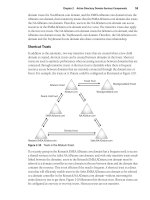
Microsoft Press windows server 2008 tcp ip protocols and services phần 2 doc
Bạn đang xem bản rút gọn của tài liệu. Xem và tải ngay bản đầy đủ của tài liệu tại đây (1.23 MB, 51 trang )
18 Part I: The Network Interface Layer
❑ The Token Ring broadcast address (0xC0-00-FF-FF-FF-FF). A frame using the
Token Ring broadcast address is designed to remain on a single ring and is not
forwarded by Token Ring source-route bridges.
❑ A multicast address.
❑ A Token Ring functional address. A functional address is a type of multicast
address that is specific to Token Ring and is typically used by Token Ring MAC
management frames.
■ Source Address The Source Address field is 6 bytes long and indicates the sending
node’s unicast address.
■ Payload The Payload field for a Token Ring frame consists of a PDU of an upper layer
protocol. Unlike Ethernet, there is no minimum frame size and the maximum transmis-
sion unit (MTU) for Token Ring is not a defined number, but dependent on factors such
as the bit rate and the token holding time. Token Ring MTUs are further complicated by
the presence of Token Ring source-routing bridges. More information on Token Ring
MTUs for IP datagrams can be found in the section titled “IEEE 802.5 SNAP,” later in
this chapter.
■ Frame Check Sequence The FCS field is a 4-byte CRC that uses the same algorithm as
Ethernet to provide a bit-level integrity check of all fields in the Token Ring frame, from
the Frame Control field to the Payload field. The FCS does not provide bit-level integrity
for the Access Control or Frame Status fields. This allows bits in these fields, such as the
Monitor bit, to be set without forcing a recalculation of the FCS.
The FCS is checked as it passes each node on the ring. If the FCS fails at any node, the
Error Detected indicator in the End Delimiter field is set to 1 and the receiving node
does not copy the frame.
■ End Delimiter The End Delimiter is a 1-byte field that identifies the end of the frame.
Like the Start Delimiter, the End Delimiter contains J and K nondata symbols to provide
an explicit postamble. The End Delimiter field also contains the following:
❑ An Intermediate Frame indicator (1 bit), used to indicate whether this frame is the
last frame in the sequence (when set to 0) or more frames are to follow (when set
to 1).
❑ An Error Detected indicator (1 bit), used to indicate whether this frame has failed
the FCS calculation.
❑ Because there is no Length field in the IEEE 802.5 frame, the End Delimiter is
used to locate the end of the payload and the position of the FCS and Frame
Status fields.
Chapter 1: Local Area Network (LAN) Technologies 19
■ Frame Status The Frame Status field is a 1-byte field that contains the following:
Two copies of the Address Recognized indicator. The destination node sets the Address
Recognized indicators to indicate that the address in the Destination Address field was
recognized.
Two copies of the Frame Copied indicator. The destination node sets the Frame Copied
indicators to indicate that the frame was successfully copied into a buffer on the net-
work adapter.
❑ Two copies of each indicator are needed because the FCS field does not protect the
Frame Status field.
❑ The Address Recognized and Frame Copied indicators are not used as acknowl-
edgments for reliable data delivery. The sending Token Ring network adapter uses
these indicators to retransmit the frame, if necessary.
Note
The FCS, End Delimiter, and Frame Status fields are not visible with
Network Monitor.
IEEE 802.2 LLC Header
The fields in the IEEE 802.2 LLC header are defined and used in the same way as the IEEE
802.2 LLC header for the IEEE 802.3 frame format, as discussed in the section titled “IEEE
802.3,” earlier in this chapter.
IEEE 802.5 SNAP
As described earlier in this chapter, the value of 0x06 is defined as the DSAP and SSAP for IP.
However, it is not defined for use in RFC 1042 and not used in the industry. Therefore, similar
to the case of IEEE 802.3 frames, to send an IP datagram over an IEEE 802.5 network, the IP
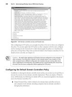
datagram must be encapsulated using SNAP, as Figure 1-7 shows.
For a 10-millisecond (ms) token-holding time, the maximum sizes for IP datagrams are 4464
bytes for 4-Mbps Token Ring network adapters and 17,914 bytes for 16-Mbps Token Ring net-
work adapters. If Token Ring source-routing bridges are present, the maximum size of IP
datagrams can be 508, 1020, 2044, 4092, and 8188 bytes. For more information on Token
Ring MTUs, see RFC 1042.
20 Part I: The Network Interface Layer
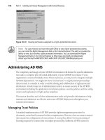
Figure 1-7 The IEEE 802.5 SNAP frame format showing the SNAP header and an IP datagram
Special Bits on Token Ring MAC Addresses
Within the Source Address and Destination Address fields of the IEEE 802.5 frame format,
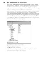
special bits are defined, as Figure 1-8 shows.
The Individual/Group Bit
Identical to Ethernet, the I/G bit for Token Ring addresses is used to indicate whether the
address is a unicast (individual) or multicast (group) address. For unicast addresses, the I/G
bit is set to 0. For multicast addresses, the I/G bit is set to 1.
The Universal/Locally Administered Bit
Identical to Ethernet, the U/L Administered bit for Token Ring addresses is used to indicate
whether the IEEE has allocated the address. For universal addresses allocated by the IEEE, the
U/L bit is set to 0. For locally administered addresses, the U/L bit is set to 1. The U/L bit is
relevant for both the Source Address and Destination Address fields.
. . .
IEEE 802.2
LLC Header
IEEE 802.5
Header
IEEE 802.5
Trailer
= 0xAA
= 0xAA
= 0x03
Start Delimiter
Access Control
Frame Control
Destination Address
Source Address
DSAP
SSAP
Control
Organization
Code
Ether Type
IP Datagram
Frame Check
Sequence
End Delimiter
Frame Status
= 0x00-00-00
SNAP
Header
= 0x08-00
Chapter 1: Local Area Network (LAN) Technologies 21
Figure 1-8 The special bits defined on Token Ring source and destination MAC addresses
Functional Address Bit
The Functional Address bit indicates whether the destination address is a functional address
(when set to 0) or a nonfunctional address (when set to 1). Token Ring defines the following
two types of multicast addresses:
■ Functional addresses Multicast addresses that are specific to Token Ring. There are spe-
cific functional addresses for identifying the ring monitor, the ring-parameter server, and
a source-routing bridge.
■ Nonfunctional addresses General multicast addresses that are not specific to Token Ring.
The Functional Address bit is significant only if the I/G bit is set to 1.
Routing Information Indicator Bit
The Routing Information Indicator bit indicates whether MAC-level routing information is
present. In the case of Token Ring, the Routing Information Indicator bit indicates the pres-
ence of a source-routing header between the IEEE 802.5 header and the IEEE 802.2 LLC
header. Token Ring source routing is not OSI Network Layer routing, but rather a MAC sub-
layer routing scheme that allows a sending node to discover and specify a route through a
defined series of rings and bridges within a Token Ring network segment.
FDDI
FDDI is a network technology developed by the American National Standards Institute
(ANSI). FDDI is an optical fiber-based token passing ring with a bit rate of 100 Mbps. It was
Destination
Address
Source
Address
0 - Individual
1 - Group
0 - Universal Admin
1 - Local Admin
0 - No Routing
1 - Routing Present
0 - Universal Admin
1 - Local Admin
0 - Functional
1 - Nonfunctional
22 Part I: The Network Interface Layer
designed to span long distances and, in most implementations, it acts as a campus-wide high-
speed backbone. FDDI offers advanced features beyond Token Ring, such as the ability to self-
heal a break in the ring and the use of guaranteed bandwidth.
Although not developed by the IEEE as part of the 802 standards, the FDDI specification is
quite similar to the IEEE 802.3 and 802.5 specifications; it defines the MAC sublayer of the
OSI Data Link Layer and the Physical Layer, and it uses the IEEE 802.2 LLC sublayer. Copper
Data Distributed Interface (CDDI) is a version of FDDI that operates over twisted-pair copper
wire.
RFC 1188 describes IP encapsulation over FDDI networks.
FDDI Frame Format
The FDDI frame format is the result of the IEEE 802.2 and ANSI FDDI specifications, and con-
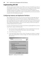
sists of an FDDI header and trailer and an IEEE 802.2 LLC header. Figure 1-9 shows the FDDI
frame format.
Figure 1-9 The FDDI frame format showing the FDDI header and trailer and IEEE 802.2 LLC header
FDDI Header and Trailer
The fields in the FDDI header and trailer are defined as follows:
■ Preamble The Preamble field is 2 bytes long and provides receiver synchronization.
■ Start Delimiter The Start Delimiter field is 1 byte long and identifies the start of the
frame. Like Token Ring, the Start Delimiter field contains nondata symbols known as J
. . .
IEEE 802.2
LLC Header
FDDI
Header
Preamble
Start Delimiter
Frame Control
Destination Address
Source Address
DSAP
SSAP
Control
Payload
Frame Check Sequence
End Delimiter
Frame Status
FDDI
Trailer
Chapter 1: Local Area Network (LAN) Technologies 23
and K symbols that are deliberate violations of the FDDI signal encoding scheme. The J
symbol is an encoding violation of a 1 and the K symbol is an encoding violation of a 0.
Note
The Preamble and Start Delimiter fields are not visible with Network Monitor.
■ Frame Control The Frame Control field is 1 byte long and contains bits for the
following:
❑ Setting the class of the frame (1 bit). FDDI frames can be sent as synchronous or
asynchronous frames. Synchronous frames are used for guaranteed bandwidth
and response time. Asynchronous frames are used for dynamic bandwidth shar-
ing. This Class bit is set to 1 for synchronous frames and 0 for asynchronous
frames.
❑ Setting the length of the Destination Address and the Source Address fields (1 bit).
Like IEEE 802.3, FDDI supports 2-byte and 6-byte addresses. The Address bit is
set to 1 for 6-byte addresses and 0 for 2-byte addresses.
❑ Indicating that what follows is a token (either nonrestricted or restricted), a
station management frame, a MAC frame, an LLC frame, or an LLC frame with
a specific priority (6 bits).
■ Destination Address The Destination Address field is either 2 bytes or 6 bytes long and
indicates the address of the destination (2-byte addresses are seldom used). For 6-byte
addresses, FDDI Destination Address fields are defined the same as Ethernet Destina-
tion Address fields to provide easy interoperability between bridged or Layer 2 switched
Ethernet and FDDI segments. The destination address is a unicast, multicast, or broad-
cast address.
■ Source Address The Source Address field is either 2 bytes or 6 bytes long and indicates
the unicast address of the sending node (2-byte addresses are seldom used).
■ Frame Check Sequence The FCS field is a 4-byte CRC that uses the same algorithm as
Ethernet to provide a bit-level integrity check of all fields in the FDDI frame, from the
Frame Control field to the Payload field. The FCS is checked as it passes each node on
the ring. If the FCS fails at any node, the Error bit in the Frame Status field is set to 1
and the receiving node does not copy the frame.
■ End Delimiter The End Delimiter field is 1 byte long and identifies the end of the frame.
Like the Start Delimiter field, the End Delimiter field contains J and K nondata symbols
to provide an explicit postamble. Because there is no Length field in the FDDI frame, the
End Delimiter field is also used to locate the end of the payload, and the position of the
FCS and Frame Status fields.
24 Part I: The Network Interface Layer
■ Frame Status The Frame Status field is typically 2 bytes long and contains bits for the
following:
The Address Recognized indicator
❑ The destination node sets the Address Recognized indicator to show that the
address in the Destination Address field was recognized.
The Frame Copied indicator
❑ The destination node sets the Frame Copied indicator to show that the frame
was successfully copied into a buffer on the network adapter.
The Error indicator
❑ Any FDDI station sets the Error indicator to 1 when the FCS field is invalid.
❑ Similar to Token Ring, the Address Recognized and Frame Copied indicators
are not used as acknowledgments for reliable data delivery. Rather, the
sending FDDI network adapter uses these indicators to retransmit the frame
if necessary.
IEEE 802.2 LLC Header
The fields in the IEEE 802.2 LLC header are defined and used in the same way as the IEEE
802.2 LLC header for the IEEE 802.3 and IEEE 802.5 frame format discussed earlier in this
chapter.
Payload
The payload for an FDDI frame consists of a PDU of an upper layer protocol. The entire FDDI
frame from the Preamble field to the Frame Status field can be a maximum size of 4500 bytes.
Once you subtract the FDDI and IEEE 802.2 LLC headers, the maximum payload size is 4474
bytes with a 3-byte LLC header, and 4473 bytes with a 4-byte LLC header.
FDDI SNAP
As described earlier in this chapter, the value of 0x06 is defined as the SAP for IP. However,
it is not defined for use in RFC 1188 and not used in the industry. Therefore, similar to
the case of IEEE 802.3 frames and IEEE 802.5 frames, to send an IP datagram over an FDDI
network, the IP datagram must be encapsulated using the SNAP header, as shown in
Figure 1-10.
The maximum-sized IP datagram that can be sent on an FDDI network is 4352 bytes. This
number of bytes is the result of taking the maximum FDDI frame size of 4500 bytes and sub-
tracting the FDDI header and trailer (23 bytes), the LLC header (3 bytes), and the SNAP
header (5 bytes) and reserving 117 bytes for future purposes.
Chapter 1: Local Area Network (LAN) Technologies 25
Figure 1-10 The FDDI SNAP frame format showing the SNAP header and an IP datagram
IP datagrams and ARP messages sent over FDDI networks also have the following constraints:
■ Only 6-byte FDDI source and destination addresses can be used.
■ All IP and ARP frames are transmitted as asynchronous class LLC frames using unre-
stricted tokens.
RFC 1188 does not define how frame priorities are used or how the FDDI node deals with the
values of the Address Recognized and Frame Copied indicators.
FDDI nodes send ARP Requests using the Ethernet ARP Hardware Type value of 0x00-01, but
can receive ARP Requests using the ARP Hardware Types of 0x00-01 and 0x00-06 (IEEE net-
works). The use of the Ethernet ARP Hardware Type value is designed to allow FDDI hosts and
Ethernet hosts in a bridged or Layer 2 switched environment to send and receive ARP messages.
Special Bits on FDDI MAC Addresses
Because FDDI MAC addresses are defined in the same way as Ethernet MAC addresses, the
special bits on FDDI MAC addresses are the same as those defined for Ethernet MAC addresses.
IEEE 802.2
LLC Header
FDDI
Header
= 0xAA
= 0xAA
= 0x03
Preamble
Start Delimiter
Frame Control
Destination Address
Source Address
DSAP
SSAP
Control
Organization Code
Ether Type
IP Datagram
Frame Check
Sequence
End Delimiter
Frame Status
= 0x00-00-00
. . . Up to 4352 bytes
SNAP
Header
FDDI
Trailer
= 0x08-00
26 Part I: The Network Interface Layer
IEEE 802.11
IEEE 802.11 is a set of standards for wireless LAN technologies. The original 802.11 standard
defines wireless networking using either 1-Mbps or 2-Mbps bit rates in the Industrial, Scien-
tific, and Medical (ISM) 2.54-gigahertz (GHz) frequency band. IEEE 802.11b defines a maxi-
mum bit rate of 11 Mbps in the 2.54-GHz ISM band. IEEE 802.11a defines a maximum bit rate
of 54 Mbps in the 5.8-GHz band. 802.11g defines a maximum bit rate of 54 Mbps in the 2.54-
GHz band. IEEE 802.11b is the most widely deployed of the IEEE 802.11 standards.
At the MAC sublayer, IEEE 802.11 (all versions) uses a combination of congestion avoidance
and Request to Send (RTS), Clear to Send (CTS), and Acknowledgment (ACK) frames to
ensure that only one wireless node is transmitting at a time and that the sent frame is success-
fully received.
IEEE 802.11 wireless nodes can communicate in the following ways:
■ Directly with each other using an operating mode known as ad hoc mode.
■ With a wireless access point (AP) using an operating mode known as infrastructure
mode. In infrastructure mode, the wireless AP acts as a transparent bridge connecting
wireless nodes to a wired network.
To identify a wireless network in either operating mode, IEEE 802.11 uses a Service Set Iden-
tifier (SSID), also known as a wireless network name.
Because wireless networking uses broadcast radio waves, a wireless node within range of a
transmitting wireless node can capture IEEE 802.11 frames and interpret the data. To provide
data confidentiality (encryption) for IEEE 802.11 payloads, IEEE 802.11 networks can use
Wi-Fi Protected Access 2 (WPA2), Wi-Fi Protected Access (WPA), or Wired Equivalent
Privacy (WEP).
IEEE 802.11 Frame Format
The IEEE 802.11 frame format consists of an IEEE 802.11 header and trailer and an IEEE
802.2 LLC header. Figure 1-11 shows the IEEE 802.11 frame format.
IEEE 802.11 Header and Trailer
The fields in the IEEE 802.11 header and trailer for a data frame sent by wireless nodes or by
a wireless AP to a wireless node are defined as follows:
■ Frame Control A 2-byte field that contains control information that defines the type of
frame and how to process the frame. For more information, see the section titled “Frame
Control Field,” later in this chapter.
■ Duration/ID Field A 2-byte field that is used to indicate the duration of time in micro-
seconds needed to transmit the frame and the acknowledgment.
Chapter 1: Local Area Network (LAN) Technologies 27
Figure 1-11 The IEEE 802.11 frame format showing the IEEE 802.11 header and trailer and
the IEEE 802.2 LLC header
■ Address 1 A 6-byte field that contains either the destination MAC address of a wireless
node (when sent by a wireless node to another wireless node in ad hoc mode or sent by
the wireless AP to the wireless node) or the SSID (when sent by a wireless node to a
wireless AP).
■ Address 2 A 6-byte field that contains either the MAC address of the sending node
(when sent to another wireless node in ad hoc mode or sent to the wireless AP) or the
SSID (when sent by the wireless AP to a wireless node).
■ Address 3 A 6-byte field that contains the SSID for frames sent to another wireless node
in ad hoc mode, the source address for frames sent from the wireless AP to a wireless
node, or the destination address for frames sent from a wireless node to a wireless AP.
■ Sequence Control A 2-byte field that contains a 4-bit Fragment Number field and a 12-bit
Sequence Number field that, when used together, allow the receiver to discard duplicate
frames. When a frame is fragmented, the Fragment Number field is used to indicate the
number of the fragment. Otherwise, the Fragment Number field is set to 0. The Sequence
Number field indicates the number of the frame starting at 0, incrementing to 4095, and
then starting again at 0. All fragments of a frame have the same sequence number.
. . .
IEEE 802.2
LLC Header
IEEE 802.11
Header
Frame Control
Duration/ID
Address 1
Address 2
Address 3
Sequence
Control
Address 4
DSAP
SSAP
Control
Organization Code
Frame Check
Sequence
IEEE 802.11
Trailer
28 Part I: The Network Interface Layer
■ Address 4 A 6-byte field that contains the MAC address of the originating wireless
node. This field is typically present only in frames in which both the To DS and From DS
flags in the Frame Control field are set to 1, indicating inter-wireless AP communication.
■ Frame Check Sequence A 4-byte CRC that uses the same algorithm as Ethernet to pro-
vide a bit-level integrity check of all fields in the IEEE 802.11 frame, from the Frame
Control field to the Payload field.
IEEE 802.2 LLC Header
The fields in the IEEE 802.2 LLC header are defined and used in the same way as the IEEE
802.2 LLC header for the IEEE 802.3, IEEE 802.5, and FDDI frame formats discussed earlier
in this chapter.
Payload
The payload for an IEEE 802.11 frame can be a maximum size of 2312 bytes. IEEE 802.11 pay-
loads can be MAC management frames (such as beacon frames sent by wireless APs), control
fames (such as RTS, CTS, and ACK frames), or data frames containing the PDU of an upper
layer protocol (such as an IP datagram).
If the payload of a data frame is encrypted with WEP, the upper layer PDU is preceded by
a plain-text 4-byte field containing an Initialization Vector (IV) field and followed with an
encrypted 4-byte Integrity Check Value (ICV) field, lowering the maximum upper layer PDU
size to 2304 bytes.
If the payload of a data frame is encrypted with WPA and the Temporal Key Integrity Protocol
(TKIP), the upper layer PDU is preceded by a plain-text 8-byte field containing the IV and fol-
lowed with an encrypted 8-byte Message Integrity Code (MIC) and 4-byte ICV field, lowering
the maximum upper layer PDU size to 2292 bytes.
If the payload of a data frame is encrypted with WPA2 and the Advanced Encryption Standard
(AES), the upper layer PDU is preceded by a plaintext 8-byte field containing the Packet Num-
ber field and followed with an encrypted 8-byte Message Integrity Code (MIC), lowering the
maximum upper layer PDU size to 2296 bytes.
The header and trailer fields for the various encryption methods are not shown in Figure 1-11.
Frame Control Field
Figure 1-12 shows the Frame Control field.
The Frame Control field contains the following subfields:
■ Protocol Version A 2-bit field that indicates the version of the 802.11 protocol used to
construct the frame. This field is set to 0 for the current version of IEEE 802.11. If the
Protocol Version field is set to a value that is not supported by the receiving wireless
node, the frame is silently discarded.
Chapter 1: Local Area Network (LAN) Technologies 29
Figure 1-12 The Frame Control field in the IEEE 802.11 header
■ Type A 2-bit field that indicates the type of IEEE 802.11 frame. There are three defined
values: 00 for management frames, 01 for control frames, and 10 for data frames. The
value of 11 is currently reserved.
■ Subtype A 4-bit field that indicates the specific type of management, control, or
data frame.
■ To DS A 1-bit flag that indicates (when set to 1) that the frame is destined for the distri-
bution system (DS), the wired network that connects wireless APs and provides access
to wired network nodes. Only wireless nodes that are operating in infrastructure mode
set this flag.
■ From DS A 1-bit flag that indicates (when set to 1) that the frame is originating from the
wired network. This flag is only set by the wireless AP when forwarding a frame to a
wireless node operating in infrastructure mode.
■ More Fragments A 1-bit flag that indicates (when set to 1) that there are more frag-
ments of the frame for which this frame is also a fragment. If the frame is not fragmented
or is the last fragment of a fragmented frame, the More Fragments flag is set to 0.
■ Retry A 1-bit flag that indicates (when set to 1) that this frame is a retransmission of a
previously transmitted frame.
■ Power Management A 1-bit flag that indicates (when set to 1) that the transmitting
wireless node is operating in a power-saving mode.
■ More Data A 1-bit flag that indicates (when set to 1) that the wireless AP has at least
one frame buffered to send to the wireless node.
■ WEP A 1-bit flag that indicates (when set to 1) that the payload is encrypted.
■ Order A 1-bit flag that indicates (when set to 1) that the frames must be processed
in order.
Protocol Version
Type
Subtype
To D S
From DS
More Fragments
Retry
Power Management
More Data
WEP
Order
30 Part I: The Network Interface Layer
IEEE 802.11 SNAP
An IP datagram sent over an IEEE 802.11 network must be encapsulated with a SNAP header.
Figure 1-13 shows SNAP encapsulation for IP datagrams sent over an IEEE 802.11 link (rather
than between wireless APs).
Figure 1-13 The IEEE 802.11 SNAP frame format showing the SNAP header and an IP datagram
Summary
LAN technology encapsulations provide delimitation, addressing, protocol identification, and
bit-level integrity services. IP datagrams and ARP messages sent over Ethernet links are encap-
sulated using either the Ethernet II or IEEE 802.3 SNAP frame formats. IP datagrams and ARP
messages sent over Token Ring links are encapsulated using the IEEE 802.5 SNAP frame for-
mat. IP datagrams and ARP messages sent over FDDI links are encapsulated using the FDDI
SNAP frame format. IP datagrams and ARP messages sent over IEEE 802.11 links are encap-
sulated using the IEEE 802.11 SNAP frame format.
. . .
IEEE 802.2
LLC Header
IEEE 802.11
Header
= 0xAA
= 0xAA
= 0x03
Frame Control
Duration/ID
Address 1
Address 2
Address 3
Sequence
Control
DSAP
SSAP
Control
Organization Code
Ether Type
IP Datagram
Frame Check
Sequence
= 0x00-00-00
SNAP
Header
IEEE 802.11
Trailer
= 0x08-00
31
Chapter 2
Wide Area Network (WAN)
Technologies
In this chapter:
WAN Encapsulations . . . . . . . . . . . . . . . . . . . . . . . . . . . . . . . . . . . . . . . . . . . . . . . . . . . 31
Point-to-Point Protocol. . . . . . . . . . . . . . . . . . . . . . . . . . . . . . . . . . . . . . . . . . . . . . . . . 32
Frame Relay. . . . . . . . . . . . . . . . . . . . . . . . . . . . . . . . . . . . . . . . . . . . . . . . . . . . . . . . . . . 38
Summary . . . . . . . . . . . . . . . . . . . . . . . . . . . . . . . . . . . . . . . . . . . . . . . . . . . . . . . . . . . . . 41
To successfully troubleshoot TCP/IP problems on a wide area network (WAN), it is important
to understand how IP datagrams and Address Resolution Protocol (ARP) messages are encap-
sulated by a computer running Windows Server 2008 or Windows Vista that uses a WAN
technology such as T-carrier, Public Switched Telephone Network (PSTN), Integrated Services
Digital Network (ISDN), or Frame Relay. It is also important to understand WAN technology
encapsulations to interpret the WAN encapsulation portions of a frame when using Microsoft
Network Monitor or other types of WAN frame capture programs or facilities.
Note
Support for Serial Line Internet Protocol (SLIP), X.25, and Asynchronous Transfer Mode
(ATM) has been removed from Windows Server 2008 and Windows Vista.
WAN Encapsulations
As discussed in Chapter 1, “Local Area Network (LAN) Technologies,” IP datagrams are an
Open Systems Interconnection (OSI) Network Layer entity that require a Data Link Layer
encapsulation before being sent on a physical medium. For WAN technologies, the Data Link
Layer encapsulation provides the following services:
■ Delimitation Frames at the Data Link Layer must be distinguished from each other,
and the frame’s payload must be distinguished from the Data Link Layer header and
trailer.
■ Protocol identification On a multiprotocol WAN link, protocols such as TCP/IP or
AppleTalk must be distinguished from each other.
■ Addressing For WAN technologies that support multiple possible destinations using
the same physical link, the destination must be identified.
32 Part I: The Network Interface Layer
■ Bit-level integrity check A checksum provides a bit-level integrity check between either
the peer nodes on the link or forwarding nodes on a packet-switching network.
This chapter discusses WAN technologies and their encapsulations for IP datagrams and ARP
messages. WAN encapsulations are divided into two categories based on the types of IP net-
works of the WAN link:
■ Point-to-point links support an IP network segment with a maximum of two nodes.
These links include analog phone lines, ISDN lines, Digital Subscriber Line (DSL) lines,
and T-carrier links such as T-1, T-3, Fractional T-1, E-1, and E-3. Point-to-point links do
not require Data Link Layer addressing.
■ Non-broadcast multiple access (NBMA) links support an IP network segment with more
than two nodes; however, there is no facility to broadcast a single IP datagram to multi-
ple locations. NBMA links include packet-switching WAN technologies such as Frame
Relay. NBMA links require Data Link Layer addressing.
Point-to-Point Protocol
The Point-to-Point Protocol (PPP) is a standardized point-to-point network encapsulation
method that provides Data Link Layer functionality comparable to LAN encapsulations. PPP
provides frame delimitation, protocol identification, and bit-level integrity services. PPP is
defined in RFC 1661.
More Info
All of the RFCs referenced in this chapter can be found in the
\Standards\Chap02_WAN folder on the companion CD-ROM.
RFC 1661 describes PPP as a suite of protocols that provide the following:
■ A Data Link Layer encapsulation method that supports multiple protocols simulta-
neously on the same link.
■ A protocol for negotiating the Data Link Layer characteristics of the point-to-point
connection named the Link Control Protocol (LCP).
■ A series of protocols for negotiating the Network Layer properties of Network Layer pro-
tocols over the point-to-point connection named Network Control Protocols (NCPs).
For example, RFCs 1332 and 1877 describe the NCP for IP called Internet Protocol
Control Protocol (IPCP). IPCP is used to negotiate an IP address, the addresses of name
servers, and the use of the Van Jacobsen TCP compression protocol.
This chapter discusses only the Data Link Layer encapsulation. Chapter 4, “Point-to-Point Pro-
tocol (PPP),” describes LCP and the NCPs needed for IP connectivity.
Chapter 2: Wide Area Network (WAN) Technologies 33
PPP encapsulation and framing is based on the International Organization for Standardiza-
tion (ISO) High-Level Data Link Control (HDLC) protocol. HDLC was derived from the
Synchronous Data Link Control (SDLC) protocol developed by IBM for the Systems Network
Architecture (SNA) protocol suite. HDLC encapsulation for PPP frames is described in RFC
1662. Figure 2-1 shows HDLC encapsulation for PPP frames.
Figure 2-1 PPP encapsulation using HDLC framing for an IP datagram
The fields in the PPP header and trailer are defined as follows:
■ Flag A 1-byte field set to the FLAG character, 0x7E (bit sequence 01111110), that indi-
cates the start and end of a PPP frame.
■ Address A 1-byte field that is a by-product of HDLC. In HDLC environments, the
Address field is used as a destination address on a multipoint network. PPP links are
point-to-point, and the destination node is always the other node on the point-to-point
link. Therefore, the Address field for PPP encapsulation is set to 0xFF—the broadcast
address.
■ Control A 1-byte field that is also an HDLC by-product. In HDLC environments, the
Control field is used to implement sequencing and acknowledgments to provide Data
Link Layer reliability services. For session-based traffic, the Control field is more than 1
byte long. For datagram traffic, the Control field is 1 byte long and set to 0x03 to indi-
cate an unnumbered information (UI) frame. Because PPP does not provide reliable
Data Link Layer services, PPP frames are always UI frames. Therefore, PPP frames always
use a 1-byte Control field set to 0x03.
■ Protocol A 2-byte field used to identify the upper layer protocol of the PPP payload. For
example, 0x00-21 indicates an IP datagram and 0x00-29 indicates an AppleTalk datagram.
For the current list of PPP protocol numbers, see
.
■ Frame Check Sequence (FCS) A 2-byte field used to provide bit-level integrity services for
the PPP frame. The sender calculates the FCS, which is then placed in the FCS field. The
Flag
Address
Control
Protocol
IP Datagram
Frame Check Sequence
Flag
=0x7E
=0xFF
=0x03
=0x00-21
=0x7E
34 Part I: The Network Interface Layer
receiver performs the same FCS calculation and compares its result with the result stored
in this field. If the two FCS values match, the PPP frame is considered valid and is pro-
cessed further. If the two FCS values do not match, the PPP frame is silently discarded.
The HDLC encapsulation for PPP frames is also used for Asymmetric Digital Subscriber Line
(ADSL) broadband Internet connections.
Figure 2-2 shows a typical PPP encapsulation for an IP datagram when using Address and
Control field suppression and Protocol field compression.
Figure 2-2 Typical PPP encapsulation for an IP datagram
This abbreviated form of PPP encapsulation is a result of the following:
■ Because the Address field is irrelevant for point-to-point links, in most cases the PPP
peers agree during LCP negotiation to not include the Address field. This is done
through the Address and Control Field Compression LCP option.
■ Because the Control is always set to 0x03 and provides no other service, in most cases
the PPP peers agree during LCP negotiation to not include the Control field. This, too, is
done through the Address and Control Field Compression LCP option.
■ Because the high-order byte of the PPP Protocol field for Network Layer protocols such
as IP or AppleTalk is always set to 0x00, in most cases the PPP peers agree during LCP
negotiation to use a 1-byte Control field. This is done through the Protocol Compression
LCP option.
Note
PPP frames captured with Network Monitor do not display the HDLC structure, as
shown in Figures 2-1 and 2-2. PPP control frames contain simulated source and destination
media access control (MAC) addresses and only the PPP Protocol field. PPP data frames con-
tain a simulated Ethernet II header.
PPP on Asynchronous Links
PPP on asynchronous links such as analog phone lines uses character stuffing to prevent the
occurrence of the FLAG (0x7E) character within the PPP payload. The FLAG character is
Flag
Protocol
IP Datagram
Frame Check Sequence
Flag
= 0x7E
= 0x21
= 0x7E
. . .
Chapter 2: Wide Area Network (WAN) Technologies 35
escaped, or replaced, with a sequence beginning with another special character called the ESC
(0x7D) character. The PPP ESC character has no relation to the ASCII ESC character.
If the FLAG character occurs within the original IP datagram, it is replaced with the sequence
0x7D-5E. To prevent the misinterpretation of the ESC character by the receiving node, if the
ESC (0x7D) character occurs within the original IP datagram, it is replaced with the sequence
0x7D-5D. Therefore:
■ FLAG characters can occur only at the beginning and end of the PPP frame.
■ On the sending node, PPP replaces the FLAG character within the IP datagram with
the sequence 0x7D-5E. On the receiving node, the 0x7D-5E sequence is translated back
to 0x7E.
■ On the sending node, PPP replaces the ESC character within the PPP frame with the
sequence 0x7D-5D. On the receiving node, the 0x7D-5D sequence is translated back to
0x7D. If the IP datagram contains the sequence 0x7D-5E, the escaping of the ESC char-
acter turns this sequence into 0x7D-5D-5E to prevent the receiver from misinterpreting
the 0x7D-5E sequence as 0x7E.
Additionally, character stuffing is used to stuff characters with values less than 0x20 (32 in
decimal notation) to prevent these characters from being misinterpreted as control characters
when software flow control is used over asynchronous links. The escape sequence for these
characters is 0x7D-x, where x is the original character with the fifth bit set to 1. The fifth bit is
defined as the third bit from the high-order bit using the bit position designation of 7-6-5-4-3-
2-1-0. Therefore, the character 0x11 (bit sequence 0-0-0-1-0-0-0-1) would be escaped to the
sequence 0x7D-31 (bit sequence 0-0-1-1-0-0-0-1).
The use of character stuffing for characters less than 0x20 is negotiated using the Asynchro-
nous Control Character Map (ACCM) LCP option. This LCP option uses a 32-bit bitmap to
indicate exactly which character values need to be escaped.
For more information on the ACCM LCP option, see RFCs 1661 and 1662.
PPP on Synchronous Links
Character stuffing is an inefficient method of escaping the FLAG character. If the PPP payload
consists of a stream of 0x7E characters, character stuffing roughly doubles the size of the PPP
frame as it is sent on the medium. For asynchronous, byte-boundary media such as analog
phone lines, character stuffing is the only alternative.
On synchronous links such as T-carrier, ISDN, and Synchronous Optical Network (SONET),
a technique called is used to mark the location of the FLAG character. Recall that
the FL AG character is 0x7E, or the bit sequence 01111110. With bit stuffing, the only time six
1 bits in a row are allowed is for the FLAG character as it is used to mark the start and end of
a PPP frame. Throughout the rest of the PPP frame, if there are five 1 bits in a row, a 0 bit is
inserted into the bit stream by the synchronous link hardware. Therefore, the bit sequence
36 Part I: The Network Interface Layer
111110 is stuffed to produce 1111100 and the bit sequence 111111 is stuffed to become
1111101. Therefore, six 1 bits in a row cannot occur except for the FLAG character when it is
used to mark the start and end of a PPP frame. If the FLAG character does occur within the
PPP frame, it is bit stuffed to produce the bit sequence 011111010. Bit stuffing is much more
efficient than character stuffing. If stuffed, a single byte becomes 9 bits, not 16 bits, as is the
case with character stuffing. With synchronous links and bit stuffing, data sent no longer falls
along bit boundaries. A single byte sent can be encoded as either 8 or 9 bits, depending on the
presence of a 11111 bit sequence within the byte.
PPP Maximum Receive Unit
The maximum-sized PPP frame, the maximum transmission unit (MTU) for a PPP link, is
known as the Maximum Receive Unit (MRU). The default value for the PPP MRU is 1500
bytes. The MRU for a PPP connection can be negotiated to a lower or higher value using the
Maximum Receive Unit LCP option. If an MRU is negotiated to a value lower than 1500 bytes,
a 1500-byte MRU must still be supported in case the link has to be resynchronized.
PPP Multilink Protocol
The PPP Multilink Protocol (MP) is an extension to PPP defined in RFC 1991 that allows you
to bundle or aggregate the bandwidth of multiple physical connections. It is supported by
Windows Server 2008 and Windows Vista Network Connections and the Windows Server
2008 Routing and Remote Access service. MP takes multiple physical connections and makes
them appear as a single logical link. For example, with MP, two analog phone lines operating
at 28.8 Kbps appear as a single connection operating at 57.6 Kbps. Another example is the
aggregation of multiple channels of an ISDN Basic Rate Interface (BRI) or Primary Rate Inter-
face (PRI) line. In the case of a BRI line, MP makes the two 64-Kbps BRI B-channels appear as
a single connection operating at 128 Kbps.
MP is an extra layer of encapsulation that operates within a PPP payload. To identify an MP
packet, the PPP Protocol field is set to 0x00-3D. The payload of an MP packet is a PPP frame
or the fragment of a PPP frame. If the size of the PPP payload that would be sent on a single-
link PPP connection, plus the additional MP header, is greater than the MRU for the specific
physical link over which the MP packet is sent, MP fragments the PPP payload.
MP fragmentation divides the PPP payload along boundaries that will fit within the link’s
MRU. The fragments are sent in sequence using an incrementing sequence number, and flags
are used to indicate the first and last fragments of an original PPP payload. A lost MP fragment
causes the entire original PPP payload to be silently discarded.
MP encapsulation has two different forms: the long sequence number format (shown in Fig-
ure 2-3) and the short sequence number format. The long sequence number format adds
4 bytes of overhead to the PPP payload.
Chapter 2: Wide Area Network (WAN) Technologies 37
Figure 2-3 The Multilink Protocol header, using the long sequence number format
The fields in the MP long sequence number format header are defined as follows:
■ Beginning Fragment Bit Set to 1 on the first fragment of a PPP payload and to 0 on all
other PPP payload fragments.
■ Ending Fragment Bit Set to 1 on the last fragment of a PPP payload and to 0 on all other
PPP payload fragments. If a PPP payload is not fragmented, both the Beginning Frag-
ment Bit and Ending Fragment Bit are set to 1.
■ Reserved Set to 0.
■ Sequence Number Set to an incrementally increasing number for each MP payload
sent. For the long sequence number format, the Sequence Number field is 3 bytes long.
The Sequence Number field is used to number successive PPP payloads that would nor-
mally be sent over a single-link PPP connection and is used by MP to preserve the packet
sequence as sent by the PPP peer. Additionally, the Sequence Number field is used to
number individual fragments of a PPP payload so that the receiving node can detect a
fragment loss.
Figure 2-4 shows the short sequence number format, which adds 2 bytes of overhead to the
PPP payload.
The short sequence format has only 2 reserved bits, and its Sequence Number field is only
12 bits long. The long sequence number format is used by default unless the Short Sequence
Number Header Format LCP option is used during the LCP negotiation.
Flag
Protocol
Beginning Fragment Bit
Ending Fragment Bit
Reserved
Sequence Number
Multilink Fragment
Frame Check Sequence
Flag
= 0x7E
= 0x3D
= 0x7E
38 Part I: The Network Interface Layer
Figure 2-4 The Multilink Protocol header, using the short sequence number format
Frame Relay
When packet-switching networks were first introduced, they were based on existing analog
copper lines that experienced a high number of errors. The X.25 packet-switched technology
was designed to compensate for these errors and provide connection-oriented reliable data
transfer. In these days of high-grade digital fiber-optic lines, there is no need for the overhead
associated with X.25. Frame Relay is a packet-switched technology similar to X.25, but with-
out the added framing and processing overhead to provide guaranteed data transfer. Unlike
X.25, Frame Relay does not provide link-to-link reliability. If a frame in the Frame Relay net-
work is corrupted in any way, it is silently discarded. Upper layer communication protocols
such as TCP must detect and recover discarded frames.
A key advantage Frame Relay has over private-line facilities, such as T-Carrier, is that Frame
Relay customers can be charged based on the amount of data transferred, instead of the dis-
tance between the endpoints. It is common, however, for the Frame Relay vendor to charge a
fixed monthly cost. In either case Frame Relay is distance-insensitive. A local connection, such
as a T-1 line, to the Frame Relay vendor’s network is required. Frame Relay allows widely sep-
arated sites to exchange data without incurring long-haul telecommunications costs.
Frame Relay is a packet-switching technology defined in terms of a standardized interface
between user devices (typically routers) and the switching equipment in the vendor’s network
(Frame Relay switches).
Typical Frame Relay service providers currently only offer permanent virtual circuits (PVCs).
A PVC is a path through a packet-switching network that is statically programmed into the
Beginning Fragment Bit
Ending Fragment Bit
Reserved
Sequence Number
Multilink Fragment
Frame Check Sequence
Flag
. . .
Flag
Protocol
= 0x7E
= 0x3D
= 0x7E
Chapter 2: Wide Area Network (WAN) Technologies 39
switches. The Frame Relay service provider establishes the PVC when the service is ordered. A
new standard for a switched virtual circuit (SVC) version of Frame Relay uses the ISDN signal-
ing protocol as the mechanism for establishing the virtual circuit. An SVC is a path through a
packet-switching network that is negotiated using a signaling protocol each time a connection
is initiated. This new standard is not widely used in production networks.
Frame Relay speeds range from 56 Kbps to 1.544 Mbps. The required throughput for a given
link determines the committed information rate (CIR). The CIR is the throughput guaranteed
by the Frame Relay service provider. Most Frame Relay service providers allow a customer to
transmit bursts above the CIR for short periods of time. Depending on congestion, the
bursted traffic can be delivered by the Frame Relay network. However, traffic that exceeds the
CIR is delivered on a best-effort basis only. This flexibility allows for network traffic spikes
without dropping frames.
Frame Relay Encapsulation
Frame Relay encapsulation of IP datagrams is based on HDLC, as RFC 2427 describes. Because
Frame Relay was designed for multiple protocols, Frame Relay encapsulation uses a Network
Layer Protocol Identifier (NLPID) field to identify the payload. IP datagrams are encapsulated
with a NLPID field set to 0xCC and a Frame Relay header and trailer. Figure 2-5 shows the
Frame Relay encapsulation for IP datagrams.
Figure 2-5 Frame Relay encapsulation for IP datagrams, showing the Frame Relay header and trailer
The fields in the Frame Relay header and trailer are defined as follows:
■ Flag As in PPP frames, the Flag field is 1 byte long and is set to 0x7E to mark the begin-
ning and end of the Frame Relay frame. Bit stuffing is used on synchronous links to pre-
vent the occurrence of the Flag character within the Frame Relay payload.
■ Address The Address field is multiple bytes long (typically 2 bytes) and contains the
Frame Relay virtual circuit identifier called the Data Link Connection Identifier (DLCI)
and congestion indicators. The Address field’s structure is discussed in the section titled
“Frame Relay Address Field,” later in this chapter.
Flag
Address
Control
= 0x7E
Frame Check Sequence
Flag
= 0x7E
NLPID
= 0xCC
= 0x03
IP Datagram
40 Part I: The Network Interface Layer
■ Control A 1-byte field set to 0x03 to indicate a UI frame.
■ NLPID A 1-byte field set to 0xCC to indicate an IP datagram.
■ Frame Check Sequence A 2-byte CRC used for bit-level integrity verification in the
Frame Relay frame. If a Frame Relay frame fails integrity verification, it is silently
discarded.
Frame Relay Address Field
The Frame Relay Address field can be 1, 2, 3, or 4 bytes long. Typical Frame Relay implemen-
tations use a 2-byte Address field, as shown in Figure 2-6.
Figure 2-6 A 2-byte Frame Relay Address field
The fields within the 2-byte Address field are defined as follows:
■ DLCI The first 6 bits of the first byte and the first 4 bits of the second byte comprise the
10-bit DLCI. The DLCI is used to identify the Frame Relay virtual circuit over which the
Frame Relay frame is traveling. The DLCI is only locally significant. Each Frame Relay
switch changes the DLCI value as it forwards the Frame Relay frame. The devices at each
end of a virtual circuit use a different DLCI value to identify the same virtual circuit.
Table 2-1 lists the defined values for the DLCI.
Table 2-1 Defined Values for the Frame Relay DLCI
DLCI Value Use
0 In-channel signaling
1–15 Reserved
16–991 Assigned to user connections
992–1022 Reserved
1023 In-channel signaling
DLCI
C/R
EA
DLCI
FECN
BECN
DE
EA
= 0
= 1
= 0
First byte
Second byte
Chapter 2: Wide Area Network (WAN) Technologies 41
■ Command/Response (C/R) The seventh bit in the first byte of the Address field is the
C/R bit. It currently is not used for Frame Relay operations and is set to 0.
■ Extended Address (EA) The last bit in each byte of the Address field is the EA bit. If this
bit is set to 1, the current byte is the last byte in the Address field. For the 2-byte Address
field, the value of the EA bit in the first byte of the Address field is 0, and the value of the
EA bit in the second byte of the Address field is 1.
■ Forward Explicit Congestion Notification (FECN) The fifth bit in the second byte of the
Address field is the FECN bit. It is used to inform the destination Frame Relay node that
congestion exists in the path from the source to the destination. The FECN bit is set to
0 by the source Frame Relay node and set to 1 by a Frame Relay switch if it is experienc-
ing congestion in the forward path. If the destination Frame Relay node receives a Frame
Relay frame with the FECN bit set, the node can indicate the congestion condition to
upper layer protocols that can implement receiver-side flow control. The interpretation
of the FECN bit for IP traffic is not defined.
■ Backward Explicit Congestion Notification (BECN) The sixth bit in the second byte of
the Address field is the BECN bit. The BECN bit is used to inform the destination Frame
Relay node that congestion exists in the path from the destination to the source (in the
opposite direction in which the frame was traveling). The BECN bit is set to 0 by the
source Frame Relay node and set to 1 by a Frame Relay switch if it is experiencing con-
gestion in the reverse path. If the destination Frame Relay node receives a Frame Relay
frame with the BECN bit set, the node can indicate the congestion condition to upper
layer protocols that can implement sender-side flow control. The interpretation of the
BECN bit for IP traffic is not defined.
■ Discard Eligibility (DE) The seventh bit in the second byte of the Address field is the
DE bit. Frame Relay switches use the DE bit to decide which frames to discard during a
period of congestion. Frame Relay switches consider the frames with the DE bit set to be
a lower priority and discards them first. The initial Frame Relay switch sets the DE bit to
1 on a frame when a customer has exceeded the CIR for the virtual circuit.
The maximum-sized frame that can be sent across a Frame Relay network varies according to
the Frame Relay provider. RFC 2427 requires all Frame Relay networks to support a mini-
mum frame size of 262 bytes, and a maximum frame size of 1600 bytes, although maximum
frame sizes of up to 4500 bytes are common. Using a maximum frame size of 1600 bytes and
a 2-byte address field, the IP MTU for Frame Relay is 1592.
Summary
Typical WAN technology encapsulations used by Windows Server 2008 and Windows Vista
provide delimitation, addressing, protocol identification, and bit-level integrity services. IP
datagrams sent over point-to-point WAN links can be encapsulated using PPP or MP. IP
datagrams and ARP messages sent over Frame Relay use an HDLC-based multiprotocol
encapsulation.