Báo cáo khoa học: " Motion compensation with a scanned ion beam: a technical feasibility study" pps
Bạn đang xem bản rút gọn của tài liệu. Xem và tải ngay bản đầy đủ của tài liệu tại đây (1.05 MB, 7 trang )
BioMed Central
Page 1 of 7
(page number not for citation purposes)
Radiation Oncology
Open Access
Research
Motion compensation with a scanned ion beam: a technical
feasibility study
Sven Oliver Grözinger, Christoph Bert, Thomas Haberer, Gerhard Kraft and
Eike Rietzel*
Address: Gesellschaft für Schwerionenforschung (GSI), Abteilung Biophysik, Planckstraße 1, 64291 Darmstadt, Germany
Email: Sven Oliver Grözinger - ; Christoph Bert - ; Thomas Haberer - ;
Gerhard Kraft - ; Eike Rietzel* -
* Corresponding author
Abstract
Background: Intrafractional motion results in local over- and under-dosage in particle therapy
with a scanned beam. Scanned beam delivery offers the possibility to compensate target motion by
tracking with the treatment beam.
Methods: Lateral motion components were compensated directly with the beam scanning system
by adapting nominal beam positions according to the target motion. Longitudinal motion
compensation to mitigate motion induced range changes was performed with a dedicated wedge
system that adjusts effective particle energies at isocenter.
Results: Lateral compensation performance was better than 1% for a homogeneous dose
distribution when comparing irradiations of a stationary radiographic film and a moving film using
motion compensation. The accuracy of longitudinal range compensation was well below 1 mm.
Conclusion: Motion compensation with scanned particle beams is technically feasible with high
precision.
Background
In conformal radiotherapy, geometric margins are com-
monly used to account for intra-fractional target motion
[1,2]. These margins inevitably lead to inclusion of
healthy tissue in the treated volume. In intensity modu-
lated radiotherapy, additional motion effects arise due to
so called interplay effects [3-5]. Treatments are delivered
in small partial doses that only result in adequate total
dosage if they match as intended. In anatomy's eye view,
target motion leads to relative displacement of partial
dose depositions and therefore results in local over- and
under-dosage.
In a pilot project at Gesellschaft für Schwerionenforsc-
hung (GSI) [6-9], approximately 400 patients have been
treated with scanned carbon ion beams with the raster-
scan system [10]. For raster scanning, the target volume is
divided in slices corresponding to equal ion energies. Irra-
diations are performed slice-by-slice. The required particle
energy is requested from the synchrotron for each slice.
Within each slice, a narrow pencil beam is scanned on a
virtual raster grid. To achieve the desired dose distribu-
tion, the number of particles is optimized for each raster
position during treatment planning including biological
effects [11-16]. The scanning progress is intensity control-
Published: 14 October 2008
Radiation Oncology 2008, 3:34 doi:10.1186/1748-717X-3-34
Received: 3 April 2008
Accepted: 14 October 2008
This article is available from: />© 2008 Grözinger et al; licensee BioMed Central Ltd.
This is an Open Access article distributed under the terms of the Creative Commons Attribution License ( />),
which permits unrestricted use, distribution, and reproduction in any medium, provided the original work is properly cited.
Radiation Oncology 2008, 3:34 />Page 2 of 7
(page number not for citation purposes)
led. The carbon ion pencil beam is directed to the next
raster position by a magnetic deflection system as soon as
the planned number of particles has been deposited. After
all points within a slice have been irradiated, the beam is
aborted and the next energy level is requested from the
accelerator. To date, only patients with tumors that are not
subject to intra-fractional motion have been treated [7,17-
19]. For treatments with scanned particle beams, target
motion would inevitably lead to local over- and under-
dosage due to the relative lateral motion between pencil
beam positions as well as possible motion induced
changes in radiological depths.
To treat moving targets, while maintaining the conformity
between target and treated volume as well as avoiding
local over- and under-dosage, we are investigating and
developing a system to adapt 3D pencil beam positions to
actual target positions in real time. Initially, simulation
studies were performed to investigate the potential of tar-
get tracking with a scanned ion beam [4,20]. In beam's eye
view, lateral motion adaptation of pencil beam positions
is feasible by applying offsets to the raster scanner settings.
Real time energy adaptation to compensate changes in
radiological depth with the synchrotron directly is not
(yet) possible. Therefore online adaptation of particle
ranges has to be performed with an additional, dedicated
energy modulation system. One of the possibilities is to
use a dedicated absorber wedge system [21].
Prototype systems for lateral as well as longitudinal target
tracking with a scanned ion beam have been developed.
Experimental results are presented to demonstrate the fea-
sibility of target tracking with a scanned ion beam and to
show the performance of the individual prototype track-
ing sub-systems.
Methods
Simulation of target motion
Lateral target motion orthogonal to the beam direction
was achieved with a three-axes positioning table. A radio-
graphic film was mounted on the table as detector. The
motion was sinusoidal with a period of ~10 s and ampli-
tudes of ± 15 mm in horizontal as well as vertical direc-
tion. No external motion monitoring device was used,
instead table motion was continuously measured with
encoders. Target displacements were evaluated from
encoder data and sent directly to the therapy control sys-
tem (TCS) for beam adaptation during irradiations.
To simulate motion induced variations in particle range,
different particle energies were requested from the syn-
chrotron. In a first experiment, three different particle
energies were requested from the accelerator repeatedly in
fixed order. The energy modulation system was used to
adapt the effective particle energy at isocenter to the mid-
dle energy. In a second experiment, six different particle
energies were requested in mixed order to test the func-
tionality of the system for variable and alternating energy
modulations. The maximum difference in energy corre-
sponded to a water equivalent range difference of 27 mm.
Again, the energy modulation system was used to adapt
the effective particle energy to a single range.
3D online motion compensation
Lateral motion compensation
The raster scanning process is controlled by the TCS. Beam
position as well as delivered number of particles are mon-
itored in intervals of ~150 μs and ~10 μs respectively. The
standard TCS can adjust small deviations of the actual
beam position via a fast feedback loop. Whenever the
beam position has been measured, possible deviations are
fed back to the control of the scanning magnets to correct
the beam position to the nominal position. Typically,
deviations are within ± 0.5 mm and corrected after each
measurement cycle. The irradiation time for an individual
raster point is typically in the order of 5–10 ms.
Several processes are running simultaneously in the TCS
including monitoring of the beam intensity, the beam
position, and the raster scanner magnet settings. The indi-
vidual processes communicate via a control loop as well
as shared memory. For motion compensation, adaptation
of lateral pencil beam positions was implemented by
dynamically changing the nominal values of the beam
positions in shared memory. As soon as the nominal val-
ues have been changed, the feedback loop adjusts the
beam position accordingly. A dedicated, additional proc-
ess running on the TCS receives displacement vectors and
then changes the nominal beam positions in shared mem-
ory accordingly. In order to avoid hardware changes
within the TCS for the prototype setup, a standard net-
work connection (100 Hz) was used to transmit displace-
ment vectors to the TCS. The actual displacement vector is
added to the stationary nominal raster point position to
compute the new, dynamic nominal position.
Longitudinal motion compensation
To perform motion compensation in longitudinal direc-
tion, the energy of individual pencil beams has to be
adjusted in quasi real time. Because fast active energy var-
iation with the accelerator is not possible, a passive energy
modulation system was developed and installed between
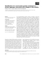
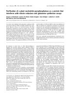
beam exit window and isocenter [21]. The system consists
of two opposing lucite wedge absorbers that are mounted
on linear motor drives orthogonal to the beam direction
(figure 1). By moving the wedges apart (together) with the
linear motors, the thickness of absorber material in the
beam path can be decreased (increased) to adapt the effec-
tive beam range at isocenter fast and continuously. The
system has an active compensation area of 120 × 150
Radiation Oncology 2008, 3:34 />Page 3 of 7
(page number not for citation purposes)
mm
2
. The absorber wedges were designed to provide
homogeneous range adaptation within the active area by
adequate overlap. If the treatment field exceeds the
dimension of the active area in the horizontal direction of
wedge motion both wedges can be moved synchronously
to provide adequate range adaptation. The total wedge
thickness of the prototype system corresponds to a maxi-
mum water equivalent range variation of ± 49.4 mm
which should exceed the maximum clinically required
range adaptation.
Measurement and analysis of dose distributions
Different detectors were used to measure dose distribu-
tions: planar radiographic films for lateral 2D dose distri-
butions and a range telescope for longitudinal 1D depth
dose distributions [22].
Radiographic films (Kodak X-Omat V) were developed
with a Kodak M35 processing machine. The films were
digitalized with a Kodak LS75 laser densitometer and the
FIPS Plus software for film dosimetry (PTW Freiburg) with
a spatial resolution of 1 mm. Based on the film responses,
absorbed doses were calculated according to Bathelt et al
[23] and Spielberger at al [24]. Simple treatment plans
were optimized to deliver homogeneous, quadratic dose
distributions as well as line patterns. Geometric properties
of motion compensation were assessed from the line pat-
terns. For quadratic fields, the homogeneity index H was
computed to compare dose distributions quantitatively:
with D
i
dose to each individual pixel, N number of pixels
within the target area, and mean dose within the target
area.
H
D
i
D
i
D
N
=−
∑−
−
1
1
2
1
()
(1)
D
Energy modulation systemFigure 1
Energy modulation system. Two opposing wedge shaped absorbers are mounted on linear motors between beam exit
window and isocenter to continuously adjust the effective energy; left: schematic drawing, right: photographs in oblique side
view (upper) and top view (lower).
Radiation Oncology 2008, 3:34 />Page 4 of 7
(page number not for citation purposes)
The range telescope was used to measure depth dose dis-
tributions, so called Bragg peaks. The telescope consists of
two parallel plate ionization chambers in front of and
behind a water tank of variable thickness [22,25,26]. Dur-
ing the measurements, the thickness of the water tank was
increased in steps of 50 μm.
Results
Lateral motion compensation
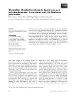
Figure 2 shows film responses for a quadratic, homogene-
ous field. Under motion, marked local over- as well as
under-dosage are apparent and relevant dose is deposited
outside of the target area. Lateral motion compensation
restored the dose distribution on the moving film. In
comparison to the reference dose distribution, only small
differences within the irradiated area are visible. Homoge-
neity indices were 0.969, 0.655, and 0.963 for the dose
distributions measured under stationary, moving, and
motion compensated conditions respectively.
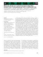
Film responses for line patterns are shown in figure 3a. In
contrast to the regular, parallel lines on the stationary
film, heavily distorted patterns were measured with the
moving film. Motion compensation successfully restored
the line patterns. A small residual motion artifact is
present in the third line from top which was attributed to
a sporadic communication delay between motion moni-
toring and compensation due to communication via a
standard network connection. Figure 3b presents line pro-
files of the film responses for stationary and motion com-
pensated measurements. Positional differences of the
lines were on average 0.2 ± 0.2 mm. A maximum devia-
tion of 1.6 mm was observed in the region of the residual
motion artifact (figure 3b; S5). Differences in relative dose
between the two experiments are within the precision of
film measurements.
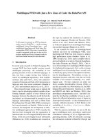
Longitudinal motion compensation
The precision of longitudinal motion compensation is
presented in figure 4. During irradiation, three different
energy levels were adapted to the middle energy using the
energy modulation system. The inlay shows that the dif-
ference to an individually measured depth dose distribu-
tion at the mean energy is ~0.1 mm.
The performance of energy adaptation for 6 different
energy levels requested in random order from the acceler-
ator is shown in figure 5. The energy modulation system
successfully restored a single, effective particle energy at
isocenter. Fluctuations around the reference depth dose
distribution of ~2.5% on average (normalized to the
Bragg peak) are mainly attributed to residual calibration
uncertainties of the energy modulation system.
Discussion
The results of our feasibility study demonstrate that
motion compensation with scanned particle beams is fea-
sible with high precision. Lateral as well as longitudinal
compensation were successfully performed during irradi-
ations. In a next step, both motion compensation sub-sys-
tems have to be integrated in the therapy control system.
Especially replacing standard network connections to
transmit compensation parameters should improve the
reliability of the system. Furthermore, hardware improve-
ments of the energy modulation system for longitudinal
Lateral motion compensationFigure 2
Lateral motion compensation. Dose distributions measured with radiographic films: stationary, moving, and moving using
lateral motion compensation. Homogeneity indices were 0.969, 0.655, and 0.963 respectively.
Radiation Oncology 2008, 3:34 />Page 5 of 7
(page number not for citation purposes)
range compensation should be investigated, and imple-
mentation of motion monitoring has to be developed.
Re-design of the wedge system for fast longitudinal
motion compensation is advisable since the thickness of
the wedges can most likely be reduced to the compensa-
tion range required for patient treatments in order to
reduce lateral scattering as well as fragmentation of the
primary particle beam [27-29]. Furthermore, the active
area of the wedge system (120 × 150 mm
2
) does currently
not match the treatment area of the scanning system (200
× 200 mm
2
). The wedge size thus has to be increased at
least in vertical direction. In contrast, the horizontal
dimension of the active area does not necessarily have to
match the scan area. If the center of mass of the wedges
follows the left-right motion of the ion beam during raster
scanning, an active area that is smaller than the maximum
treatment area is sufficient. However, less wedge motion
and therefore reduced system performance is required if
the active area is sufficiently large to cover the complete
scanning area. Detailed requirements on the compensa-
tion speed have to be derived from simulation studies, for
example based on 4D computed tomography data [30-
32].
Geometrical performance of lateral motion compensationFigure 3
Geometrical performance of lateral motion compensation. a) Line patterns irradiated on radiographic films: station-
ary, moving, and moving using lateral motion compensation. b) Line profiles of the particle fluences in vertical direction at the
positions indicated on the film measurements.
Radiation Oncology 2008, 3:34 />Page 6 of 7
(page number not for citation purposes)
Another problem of motion tracking that has not yet been
solved adequately is precise monitoring of target motion.
To date, several different methods have been reported in
the literature. Currently, the most promising technique
seems to be fluoroscopic motion detection because target
motion is imaged directly [33-38]. Other techniques that
monitor external surface motion have to be evaluated
regarding the accuracy to derive target positions [39-46].
Since the particle range and thus the Bragg peak position
are influenced by target motion and currently no motion
monitoring system exists to determine changes in water-
equivalent range a link to 4D treatment planning is
required [47,48]. Motion states from 4DCT which are
used to determine range changes could be detected by
motion monitoring. Compensation vectors are then cal-
culated during treatment planning and applied according
to detected motion states. In case of motion irregularities
or unknown motion states the treatment can be paused
until the patient is back to normal breathing.
Conclusion
The results of our study demonstrate the high precision
that is technically feasible for motion tracking with
scanned particle beams. Lateral motion compensation
restored homogeneous dose distributions delivered to
moving targets. Differences in dose uniformity between
irradiation of a stationary radiographic film and a moving
film using motion compensation were below 1%. Longi-
tudinal compensation precision was well below 1 mm.
Competing interests
SOG and ER are now employed by Siemens Healthcare.
Research was performed while both were employed by
GSI.
Authors' contributions
All authors contributed to the design of the prototype sys-
tem and the conceptual design of the study. Furthermore,
SOG performed measurements, analyzed data, and
drafted the manuscript. CB and ER supported measure-
ments, analyzed data, and revised the manuscript. TH and
GK improved the conceptual design and revised the man-
uscript. All authors read and approved the final manu-
script.
References
1. ICRU: Report 50. Bethesda, Md, USA, International Commission on
Radiation Units and Measurements; 1993.
2. ICRU: Report 62. Bethesda, Md, USA, International Commission on
Radiation Units and Measurements; 1999.
3. Phillips MH, Pedroni E, Blattmann H, Boehringer T, Coray A, Scheib
S: Effects of respiratory motion on dose uniformity with a
charged particle scanning method. Phys Med Biol 1992,
37:223-233.
4. Grozinger SO, Rietzel E, Li Q, Bert C, Haberer T, Kraft G: Simula-
tions to design an online motion compensation system for
scanned particle beams. Phys Med Biol 2006, 51:3517-3531.
5. Bert C, Grözinger SO, Rietzel E: Quantification of interplay
effects of scanned particle beams and moving targets. Phys
Med Biol 2008, 53:2253-2265.
6. Kraft G: Tumor Therapy with Heavy Charged Particles. Prog
Part Nucl Phys 2000, 45:473.
7. Debus J, Haberer T, Schulz-Ertner D, Jakel O, Wenz F, Enghardt W,
Schlegel W, Kraft G, Wannenmacher M: Carbon ion irradiation of
skull base tumors at GSI. First clinical results and future per-
spectives. Strahlenther Onkol 2000, 176:211-216.
8. Schulz-Ertner D, Jakel O, Schlegel W: Radiation therapy with
charged particles. Semin Radiat Oncol 2006, 16:249-259.
9. Schulz-Ertner D, Tsujii H: Particle Radiation Therapy Using Pro-
ton and Heavier Ion Beams. J Clin Oncol 2007, 25:953-964.
Longitudinal motion compensationFigure 4
Longitudinal motion compensation. Bragg peaks meas-
ured for three different energies and obtained by longitudinal
motion compensation to the central energy. The inlay shows
the sub-millimeter accuracy of longitudinal motion compen-
sation.
Performance of longitudinal motion compensation for mixed energiesFigure 5
Performance of longitudinal motion compensation
for mixed energies. Longitudinal motion compensation for
6 different energies requested in random order over a range
of 27 mm water-equivalence. Horizontal bars indicate the
compensation precision of 0.1 mm water-equivalent.
Radiation Oncology 2008, 3:34 />Page 7 of 7
(page number not for citation purposes)
10. Haberer T, Becher W, Schardt D, Kraft G: Magnetic scanning sys-
tem for heavy ion therapy. Nucl Instrum Meth A 1993,
330:296-305.
11. Krämer M, Scholz M: Treatment planning for heavy-ion radio-
therapy: calculation and optimization of biologically effec-
tive dose. Phys Med Biol 2000, 45:3319-3330.
12. Krämer M, Jäkel O, Haberer T, Kraft G, Schardt D, Weber U: Treat-
ment planning for heavy-ion radiotherapy: physical beam
model and dose optimization. Phys Med Biol 2000, 45:3299-3317.
13. Krämer M, Scholz M: Rapid calculation of biological effects in
ion radiotherapy. Phys Med Biol 2006, 51:1959-1970.
14. Scholz M, Kraft G: Calculation of heavy ion inactivation proba-
bilities based on track structure, x ray sensitivity and target
size. Radiat Prot Dosim 1994, 52:29-33.
15. Scholz M, Kellerer AM, Kraft-Weyrather W, Kraft G: Computation
of cell survival in heavy ion beams for therapy. The model
and its approximation. Radiat Environ Biophys 1997, 36:59-66.
16. Jäkel O, Krämer M, Karger CP, Debus J: Treatment planning for
heavy ion radiotherapy: clinical implementation and applica-
tion. Phys Med Biol 2001, 46:1101-1116.
17. Schulz-Ertner D, Nikoghosyan A, Thilmann C, Haberer T, Jäkel O,
Karger C, Kraft G, Wannenmacher M, Debus J: Results of carbon
ion radiotherapy in 152 patients. Int J Radiat Oncol 2004,
58:631-640.
18. Schulz-Ertner D, Nikoghosyan A, Hof H, Didinger B, Combs SE, Jakel
O, Karger CP, Edler L, Debus J: Carbon ion radiotherapy of skull
base chondrosarcomas. Int J Radiat Oncol Biol Phys 2007,
67:171-177.
19. Nikoghosyan A, Schulz-Ertner D, Didinger B, Jakel O, Zuna I, Hoss A,
Wannenmacher M, Debus J: Evaluation of therapeutic potential
of heavy ion therapy for patients with locally advanced pros-
tate cancer. Int J Radiat Oncol Biol Phys 2004, 58:89-97.
20. Li Q, Grözinger SO, Haberer T, Rietzel E, Kraft G: Online compen-
sation of target motion with scanned particle beams: simula-
tion environment. Phys Med Biol 2004, 49:
3029-3046.
21. Weber U, Becher W, Kraft G: Depth scanning for a conformal
ion beam treatment of deep seated tumours. Phys Med Biol
2000, 45:3627-3641.
22. Sihver L, Schardt D, Kanai T: Depth-dose distributions of high-
energy carbon, oxygen and neon beams in water. Jpn J Med
Phys 1998, 18:1-21.
23. Bathelt B: Filmdosimetrie in der Schwerionen-Tumortherapie: 3-dimension-
ale Dosisverifikation in gemischten Teilchenstrahlfeldern Gesamthochs-
chule Kassel; 2000.
24. Spielberger B, Scholz M, Krämer M, Kraft G: Experimental inves-
tigations of the response of films to heavy-ion irradiation.
Phys Med Biol 2001, 46:2889-2897.
25. Schardt D, Stelzer H, Junk H, Arndt U: Bragg curve measure-
ments with ionisation chambers. Grundinger, U. 336. Darm-
stadt, Gesellschaft für Schwerionenforschung mbH. GSI Scientific Report
1992 1993.
26. Rietzel E, Schardt D, Haberer T: Range accuracy in carbon ion
treatment planning based on CT-calibration with real tissue
samples. Radiat Oncol 2007, 2:14.
27. Schardt D, Schall I, Geissel H, Irnich H, Kraft G, Magel A, Mohar MF,
Munzenberg G, Nickel F, Scheidenberger C, Schwab W, Sihver L:
Nuclear fragmentation of high-energy heavy-ion beams in
water. Adv Space Res 1996, 17:87-94.
28. Schall I, Schardt D, Geissel H, Irnich H, Kankeleit E, Kraft G, Magel A,
Mohar MF, Mnnzenberg G, Nickel F, Scheidenberger C, Schwab W:
Charge-changing nuclear reactions of relativistic light-ion
beams (5 <= Z <= 10) passing through thick absorbers. Nucl
Instrum Meth B 1996, 117:221-234.
29. Gunzert-Marx K, Iwase H, Schardt D, Simon RS: Secondary beam
fragments produced by 200 MeVu(-1) C-12 ions in water and
their dose contributions in carbon ion radiotherapy. New Jour-
nal of Physics 2008, 10:.
30. Ford EC, Mageras GS, Yorke E, Ling CC: Respiration-correlated
spiral CT: A method of measuring respiratory-induced ana-
tomic motion for radiation treatment planning. Med Phys
2003, 30:88-97.
31. Vedam SS, Keall PJ, Kini VR, Mostafavi H, Shukla HP, Mohan R:
Acquiring a four-dimensional computed tomography data-
set using an external respiratory signal. Phys Med Biol 2003,
48:45-62.
32. Rietzel E, Pan T, Chen GTY: Four-dimensional computed tom-
ography: Image formation and clinical protocol. Med Phys
2005, 32:874-889.
33. Shirato H, Shimizu S, Kunieda T, Kitamura K, Kagei K, Nishioka T,
Hashimoto S, Fujita K, Aoyama H: Physical aspects of a real-time
tumor-tracking system for gated radiotherapy. Int J Radiat
Oncol 2000, 48:1187-1195.
34. Berbeco RI, Jiang SB, Sharp GC, Chen GTY, Mostafavi H, Shirato H:
Integrated radiotherapy imaging system (IRIS): design con-
siderations of tumour tracking with linac gantry-mounted
diagnostic x-ray systems with flat-panel detectors. Phys Med
Biol 2004, 49:243-255.
35. Shirato H, Harada T, Harabayashi T, Hida K, Endo H, Kitamura K,
Onimaru R, Yamazaki K, Kurauchi N, Shimizu T, Shinohara N, Matsu-
shita M, aka-Akita H, Miyasaka K: Feasibility of insertion/implan-
tation of 2.0-mm-diameter gold internal fiducial markers for
precise setup and real-time tumor tracking in radiotherapy.
Int J Radiat Oncol Biol Phys 2003, 56:240-247.
36. Shimizu S, Shirato H, Kitamura K, Shinohara N, Harabayashi T, Tsu-
kamoto T, Koyanagi T, Miyasaka K: Use of an implanted marker
and real-time tracking of the marker for the positioning of
prostate and bladder cancers. Int J Radiat Oncol 2000,
48:1591-1597.
37. Schweikard A, Shiomi H, Adler J: Respiration tracking in radio-
surgery. Med Phys 2004, 31:2738-2741.
38. Rietzel E, Rosenthal SJ, Gierga DP, Willet CG, Chen GT: Moving
targets: detection and tracking of internal organ motion for
treatment planning and patient set-up. Radiother Oncol 2004,
73(Suppl 2):S68-S72.
39. Baroni G, Ferrigno G, Pedotti A: Implementation and applica-
tion of real-time motion analysis based on passive markers.
Med Biol Eng Comput 1998, 36:693-703.
40. Kubo HD, Len PM, Minohara S, Mostafavi H: Breathing-synchro-
nized radiotherapy program at the University of California
Davis Cancer Center. Med Phys 2000, 27:346-353.
41. Ford EC, Mageras GS, Yorke E, Rosenzweig KE, Wagman R, Ling CC:
Evaluation of respiratory movement during gated radiother-
apy using film and electronic portal imaging.
Int J Radiat Oncol
2002, 52:522-531.
42. Smith N, Meir I, Hale G, Howe R, Johnson L, Edwards P, Hawkes D,
Bidmead M, Landau D: Real-time 3D surface imaging for patient
positioning in radiotherapy. Int J Radiat Oncol 2003, 57:S187.
43. Kuechler S, Hoinkis C, Thierfelder C, Becker B, Zahn P, Geyer P, Leh-
mann D: Respiratory motion – first investigations on the opti-
mization of gating parameters. Int J Radiat Oncol 2004, 60:579.
44. Bert C, Metheany KG, Doppke K, Chen GT: A phantom evalua-
tion of a stereo-vision surface imaging system for radiother-
apy patient setup. Med Phys 2005, 32:2753-2762.
45. Li XA, Stepaniak C, Gore E: Technical and dosimetric aspects of
respiratory gating using a pressure-sensor motion monitor-
ing system. Med Phys 2006, 33:145-154.
46. Willoughby TR, Forbes AR, Buchholz D, Langen KM, Wagner TH,
Zeidan OA, Kupelian PA, Meeks SL: Evaluation of an infrared
camera and X-ray system using implanted fiducials in
patients with lung tumors for gated radiation therapy. Int J
Radiat Oncol Biol Phys 2006, 66:568-575.
47. Rietzel E, Chen GTY, Choi NC, Willet CG: Four-dimensional
image-based treatment planning: Target volume segmenta-
tion and dose calculation in the presence of respiratory
motion. Int J Radiat Oncol 2005, 61:1535-1550.
48. Bert C, Rietzel E: 4D treatment planning for scanned ion
beams. Radiat Oncol 2007, 2:.