Google SketchUp Cookbook phần 4 pps
Bạn đang xem bản rút gọn của tài liệu. Xem và tải ngay bản đầy đủ của tài liệu tại đây (1.22 MB, 39 trang )
100
|
Chapter 4: Advanced Intersect and Follow Me Techniques
Copy one of the side faces of the box to the end of 3.
the arc. On this face, draw a cross-section for steps
(Figure 4-65).
Figure 4-65
Using all three segments of the arc as the Follow Me 4.
path, and the step section as the Follow Me face,
create the steps (Figure 4-66).
Figure 4-66
On the back of the box, make a face like the one 5.
indicated in Figure 4-67, using tangent arcs.
Figure 4-67
The Follow Me path for this face is another extend-6.
ed path, going past the back of the tub steps, so the
curved walls will be easy to trim behind the steps.
Select all of the top edges of the box as the Follow
Me path (not including the edge along the back
face) and run Follow Me on this face. This creates
the curvy walls of the hot tub. If you have extra ver-
tical faces around the tub, erase them (Figure 4-68).
Figure 4-68
Run Intersect with Model on the entire model, and 7.
trim the walls and steps that extend past each other
(Figure 4-69). Because the paths for these objects
were extended, trimming is easy.
Figure 4-69
Extending Follow Me Paths
|
101
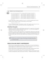
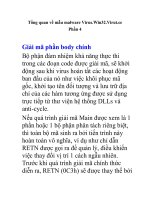
The last step is to fill the tub with water. The easiest 8.
way to make a face to represent the water level is to
make a simple box next to the hot tub, at the height
you want for the water. Remove all but the top face
of this box, and move edges until they intersect the
tub (Figure 4-70).
Figure 4-70
Intersect and trim. You can paint this face with a 9.
translucent water material from the Water category
(Figure 4-71).
Figure 4-71
Other Uses
The extended path technique can be applied to window
frames. This section shows two examples of such win-
dows: a stained-glass window that you might see in an
old church and a more modern three-paned window.
Stained-glass window
Figure 4-72 shows windows whose frames have two
parts, created using two separate Follow Me faces. The
Follow Me paths are extended past one another, and
each Follow Me face is a group. After both Follow Me
face groups are extruded along their paths, they are
exploded, intersected, and trimmed. After the window
is made into a component that cuts walls, it can be
inserted into walls.
To see how it’s done, download my Stained Glass Win-
dow model from the 3D Warehouse.
Three-paned window
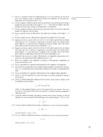
Figure 4-73 shows a window with three panes. The
window frame is created using Follow Me on the frame
face. The muntins separating the panes are created
with a simple Push/Pull, starting and ending past the
window frame. Intersect and trim, make the window a
component, and insert.
To see how it’s done, download my Three Paned Win-
dow model from the 3D Warehouse.
Figure 4-72
Figure 4-73
102
|
Chapter 4: Advanced Intersect and Follow Me Techniques
Using Intersect to Create a 3D Follow Me Path4.7
Problem
You want to use Follow Me along a 3D path, but it is difficult to draw the path.
Solution
Use the Intersect tool to create the path.
Discussion
Recipe 2.7 demonstrated how to use grouped reference geometry to create a 3D Follow Me
path. This recipe presents another technique for creating a 3D path, in which intersection edges
between two objects create the Follow Me path. This technique is helpful in cases where refer-
ence geometry is not easy to draw, but you do know the basic 3D parameters of the path.
In this recipe, you will model a pair of glasses. The frame around each lens proceeds along a 3D
path, which is the intersection of a partial sphere and the frame shape. In the “Other Uses” sec-
tion, the same technique is used to create a window frame around a curved window.
Create the Lens
This section demonstrates how to intersect two objects
to produce the 3D Follow Me path. You’ll create one
lens for the glasses, whose border edges form the 3D
path.
In Top view, use Arc and Line to make a face (Fig-1.
ure 4-74).
Make a vertical circle centered at the line’s midpoint 2.
(Figure 4-75).
Figure 4-74
Figure 4-75
Use the large circle as the Follow Me path for the 3.
lens face. After you run Follow Me on the lens face,
you will have a partial sphere. Erase the circle. What
remains is the curved glass from which the lens will
be cut (Figure 4-76).
Figure 4-76
Using Intersect to Create a 3D Follow Me Path
|
103
To give the lens glass some thickness, make a copy 4.
of it slightly in front or behind (Figure 4-77).
Paint the lens glass with a translucent material.5.
Figure 4-77
In Front view, in some blank space next to the lens, 6.
draw a shape for the lens frame (Figure 4-78). My
frame is a simple oval (created by using the Scale
tool on a circle), but you could use a rectangle with
rounded corners, a star, or whatever shape you
want.
Figure 4-78
Pull out the lens shape and move it into the lens 7.
glass (Figure 4-79).
Figure 4-79
Intersect and trim (Figure 4-80).8.
Figure 4-80
104
|
Chapter 4: Advanced Intersect and Follow Me Techniques
Make the Lens Frame
The border around the front of the lens will be used
as the 3D path, and this path will be used to create the
frame.
On one side of the lens, draw a shape to use as the 1.
Follow Me face for the frame (Figure 4-81). My
Follow Me face is a rectangle, but you could try a
curved shape.
To prevent the Follow Me frame from breaking the 2.
lens, make the Follow Me face a group.
You know that when a face is 2D, you can select3. it
to define its boundary as the Follow Me path. But
when the path is 3D, you need to select the Follow
Me edges, and not the face. To select the edges bor-
dering this face, double-click the front face of the
lens and then Shift-click to unselect the face. This
leaves only the edges selected.
Run Follow Me on the frame shape group. To 4.
remove the little edges throughout the frame, select
everything inside the group, right-click, and choose
Soften→Smooth Edges. Adjust the sliders until the
edges disappear (Figure 4-82).
Close the frame group.5.
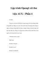
To make the second lens and frame, copy the 6.
framed lens next to the original and leave the copy
selected.
To ensure that the pair of glasses is symmetric, 7.
activate Scale, which will be used to turn the copy
inside-out. Click the drag handle in the direction
you want to scale (Figure 4-83).
Figure 4-81
Figure 4-82
Figure 4-83
For the scale value, enter 8. –1. Then move the copy
so that the spacing between the lenses looks correct
(Figure 4-84).
Note
Another way to mirror an object is to right-click on it and
choose Flip Along with the relevant axis direction.
Figure 4-84
Using Intersect to Create a 3D Follow Me Path
|
105
To make the nosepiece, add an arc between the 9.
frames, plus a small Follow Me face (Figure 4-85).
Because the frames are grouped, these new objects
don’t stick to them.
Figure 4-85
Finish the nosepiece and make the ear pieces 10.
the same way: Use Follow Me and then make an
inside-out copy. The completed pair of glasses is
shown in Figure 4-86.
Figure 4-86
Other Uses
This technique can be used to add a frame to a curved
window.
The method to create the window itself is described in
Recipe 3.4. In the example in Figure 4-87, the window
glass is along the front of the window, not the back or
middle. This makes it easier to define the path for the
frame. The window itself is a component.
Figure 4-87
Edit the window component and add a shape for the
frame (shown in Figure 4-88 in yellow). Make the frame
shape a group.
Figure 4-88
106
|
Chapter 4: Advanced Intersect and Follow Me Techniques
Extrude the frame around the border of the glass and
smooth the edges. Run Intersect with Model on the
frame, to get the edges where the frame meets the walls
of the building (Figure 4-89).
Figure 4-89
Trim the frame, close the frame group, close the win-
dow component, and you have a window with a curved
frame (Figure 4-90).
Figure 4-90
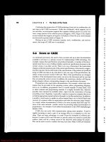
To master SketchUp, understanding constraints
is a must. You know the basics: a red preview
line means a line will be drawn parallel to the red
axis, and so on. You may even be an old hand at
Shift-locking, aware that pressing and holding
Shift while a preview line is red keeps the line
in the red direction. But have you used double
constraints or tried using the arrow keys? In this
chapter, you’ll learn about these and many more
powerful ways constraints can help you work
more accurately and effectively.
Most of the recipes involve roofs, which can pose
vexing problems in building design but benefit
from well-applied constraints. Even if you’re not
an architect, keep reading. The techniques pre-
sented are great for a wide variety of projects, be-
cause learning how to use SketchUp’s constraints
is simply essential to efficient design.
Inferences in SketchUp are those colored dots and
dashed lines, and helpful text boxes, that appear
while drawing, such as On Red Axis, On Face, Mid-
point, and so forth. You can use inferences to ensure
that you are drawing lines in the correct direction
(red, green, or blue), starting a line at the right place
(on an edge, endpoint, or midpoint), or drawing an
object on a face. In addition to those basic uses, infer-
ences also can be used to constrain objects, either to
another object or to a direction. Constraining means
you are forcing an object to have a certain geometric
characteristic, such as a direction or start point.
CHAPTER 5
Roofs: Constraints and Inferences
108
|
Chapter 5: Roofs: Constraints and Inferences
Creating an Overhanging Roof5.1
Problem
You want to create an overhanging roof on a simple, rectangular house.
Solution
Use Push/Pull to create the overhanging parts of the roof, and use inferences and Shift-locking
to fill the resulting gap.
Discussion
One quick and easy solution for adding an overhanging roof to a simple, rectangular building is
to create both the roof thickness and overhang by using Push/Pull. Unfortunately, the method
also results in an unwanted gap at the ridgeline. This recipe demonstrates two ways to fix that
gap. The first approach is to fill in the gap with constrained lines, forming a new face that can
be pulled along the entire ridge. The second option is to move the top edges of the roof while
locking constraints.
Note
For more suggestions on working with overhanging roofs, see
Recipe 4.4, which presents a solution for creating a uniform
overhanging roof on a building with several sections, or
Recipe 5.4, which demonstrates using Autofold and a planar
constraint for creating overhangs.
Start with a house like the one in Figure 5-1. (Make 1.
a simple box with a line between midpoints along
the top face. Then use Move to move this line
straight up.)
Figure 5-1
To give the roof some thickness, use Push/Pull with 2.
Ctrl/Option to pull out one roof face. Press Ctrl/
Option again and double-click the other roof face
to pull it out the same amount (Figure 5-2).
Figure 5-2
Creating an Overhanging Roof
|
109
Use Push/Pull again to pull down both bottom faces 3.
(Figure 5-3).
Notice the gap at the top of the roof. You can fix it
in a couple of ways.
Figure 5-3
The first method of closing the gap is to add lines. 4.
Start a line at the point indicated in Figure 5-4.
Figure 5-4
With your cursor, hover on the edge indicated in 5.
Figure 5-5. You should see the On Edge inference.
Figure 5-5
Hover the cursor over the valley point indicated in 6.
Figure 5-6; look for the Endpoint inference.
Figure 5-6
110
|
Chapter 5: Roofs: Constraints and Inferences
You have just “reminded” SketchUp of the geome-7.
try of that edge and point, so SketchUp can produce
inferences from them. Move the cursor straight up
from the valley point, keeping the dotted blue infer-
ence line. Stop when you also see a magenta pre-
view line starting from the endpoint of the angled
edge you hovered over (Figure 5-7). This means
that the point you are about to click is the endpoint
of the extension of that edge, and is also directly
above the valley point. This is a double constraint.
Figure 5-7
Click this point. Then complete the small diamond-8.
shaped face by connecting another line to the op-
posite corner of the gap. Pull this small face to the
other side of the house (Figure 5-8).
If you were to continue with this method, you 9.
would erase the extra lines. Instead, choose Undo
until the gap is back, and move on to the second
method.
Figure 5-8
Select the edge indicated in Figure 5-9. This edge 10.
will be moved into place by using another double
constraint.
Figure 5-9
Activate Move. For the first move point, click the 11.
corner point indicated in Figure 5-10.
Figure 5-10
Creating an Overhanging Roof
|
111
Hover over the lower edge of the same side of the 12.
roof, indicated in Figure 5-11.
Figure 5-11
Move the cursor slightly out from the edge, until 13.
you see the Parallel to Edge inference (Figure 5-12).
Figure 5-12
Press Shift to lock the magenta inference, and 14.
click anywhere on the opposite sloped roof face.
This moves the edge so that both constraints are
satisfied—the new edge is still parallel to the edge
below, and it lies on the extension of the opposite
roof face (Figure 5-13).
Repeat steps 10 through 14 to move the other gap 15.
edge the same way, and erase extra lines.
You’ll use this model again in Recipe 5.2’s “Example 2:
Coplanar Dormer.” You can either save your model now
or download a fresh model later, if you prefer.
Figure 5-13
112
|
Chapter 5: Roofs: Constraints and Inferences
Creating Dormers5.2
Problem
You want to place a dormer in a roof.
Solution
Use inferences and locking constraints to create dormers.
Discussion
Dormers, which are vertical windows cut into a roof, present interesting design challenges.
How do you project the side edges of a dormer to reach the slope of the roof, or how do you
keep the dormer face coplanar with the rest of the house? Inferences and constraints make this
easy. You can constrain points to edges, faces, or axis directions, and the Shift key enables you
to use double constraints (for example, constraining a point to both the red direction and to a
specific face). Arrow keys can also be used to lock the red, green, and blue directions.
This recipe demonstrates the advantages of inference locking and constraints by using three
types of dormers, which get progressively more complex. The first dormer is a simple box cut
into a straight roof. The second is created on an overhanging roof, constrained to the side of the
house below the roof. The third has a peaked shape, and points on its front face are constrained
to existing objects (windows) on the house.
Example 1: Simple Dormer
The first example is a simple review of the basics of
locking a direction. You will create a dormer from a
rectangle drawn in a roof. With the help of direction
locking, you’ll position the dormer and place a copy in
relation to other model elements (existing windows).
Start with a model like the one in Figure 5-14. You 1.
can create your model from scratch, or download
my Simple Dormer model from the 3D Warehouse.
Figure 5-14
Draw a rectangle in the roof. For the side of the 2.
dormer, start a line at the lower corner (where
indicated in Figure 5-15). Move your cursor (don’t
click yet) straight up or down, in the blue direction.
Press and hold Shift to lock this direction. The blue
preview line turns bold to indicate that its direction
is locked.
Figure 5-15
Creating Dormers
|
113
With Shift still pressed, hover over any point along 3.
the back edge of the dormer rectangle. This sets the
height of the dormer wall to match the height of the
back edge of the rectangle. The inference should
read Constrained on Line from Point (Figure 5-16).
Figure 5-16
Click to finish the line and then add the horizontal 4.
edge to complete the triangle (Figure 5-17). This is
the side of the dormer.
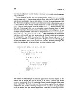
Use Push/Pull to complete the dormer.5.
Figure 5-17
To change the flat roof into a sloped one, use Move 6.
to slightly push down the front edge (Figure 5-18).
Figure 5-18
Hide the top face of the dormer and cut a hole in 7.
the roof below the dormer (Figure 5-19).
Unhide the top of the dormer and add a glass win-8.
dow to the dormer front.
Figure 5-19
114
|
Chapter 5: Roofs: Constraints and Inferences
The next step is to move the dormer directly above 9.
one of the windows already on the house, which
will require direction locking. Select the whole dor-
mer and activate Move. Click the dormer’s lower-
left front corner and start to move the dormer in
the green direction (or red, depending on how you
made your house). Press and hold Shift to lock the
direction. Then click any point along the left edge
of the window below. This aligns the left side of the
dormer with the left side of the window below it
(Figure 5-20).
Figure 5-20
To make the dormer the correct width, select all of 10.
the vertical edges on the right side (use a left-to-
right selection window and check your selection
in Wireframe mode). Move the selected edges by
any point on the right edge, Shift-lock the green (or
red) direction, and click any point on the right edge
of the window below the dormer (Figure 5-21).
Figure 5-21
Copy the entire dormer to the right, so that it sits 11.
above the other window (Figure 5-22). For the
move points, use similar reference points on the
windows below.
Figure 5-22
Example 2: Coplanar Dormer
The dormer in this example is cut into an overhanging
roof. The front face of the dormer will lie in the same
plane as the side wall of the house. For this design, you
need a constraint that locks two faces.
Start with a model like the one shown in Figure 1.
5-23. You can reuse your model from Recipe 5.1,
or you can download my Coplanar Dormer model
from the 3D Warehouse.
Figure 5-23
Creating Dormers
|
115
The front face of the dormer will lie in the same 2.
plane as the side of the house. Activate Line (don’t
click yet) and hover over the side face (Figure 5-24).
Press and hold Shift.
Figure 5-24
Move the cursor up to the roof face. The black 3.
point at the end of the dashed black inference line
follows the cursor, and the dark blue point lets you
know where the line will meet the roof face. This is
a double constraint: Constrained on Plane Intersect
Plane. Click where you want to start the dormer
(Figure 5-25).
Figure 5-25
Draw the four lines for the dormer face (Figure 4.
5-26). Make sure to draw the vertical lines in the
blue direction.
Figure 5-26
For the side face, start a line at the lower-left 5.
dormer corner and hover over the side edge of the
roof to inference the slope of that edge. Draw a line
parallel to that edge (Figure 5-27).
Figure 5-27
116
|
Chapter 5: Roofs: Constraints and Inferences
For the next line, Shift-lock the green (or red) 6.
direction and click the lower-right corner (Figure
5-28).
Figure 5-28
Add two more lines to complete the two sides (Fig-7.
ure 5-29).
Figure 5-29
The roof of the dormer should have some thickness. 8.
Use Push/Pull with Ctrl/Option to pull the roof up.
Then pull out the three exposed sides of the roof
(Figure 5-30).
Figure 5-30
One way to fill the gap between the dormer roof 9.
and the main roof is to add lines. Start a line at the
back corner (shown by the yellow arrow in Figure
5-31) and hover over the top side edge (blue arrow).
Figure 5-31
Creating Dormers
|
117
Press and hold Shift to lock the line to the direc-10.
tion of the side edge, and click the main roof face
(Figure 5-32).
Complete the triangle to fill the gap on the side. 11.
Then pull the triangle to the other side of the
dormer.
Figure 5-32
If you want to make sure your dormer is coplanar 12.
with the house side, orbit to the view shown in
Figure 5-33. The two faces should line up.
Figure 5-33
Example 3: Peaked Dormer
The last dormer is a bit more complicated, because its
main shape is peaked rather than a straight rectangle.
This dormer will start directly above one of the existing
windows. This example also uses the arrow keys, which
provide another way to both find and lock the red,
green, and blue directions.
Draw the peaked dormer face
In this phase, you’ll use constraints to draw the front
face of the peaked dormer.
Start with a house like the one in Figure 5-34. The 1.
windows have frames that protrude slightly from
the side wall of the house. You can create this model
from scratch, or download my Peaked Dormer
model from the 3D Warehouse.
The front of the dormer will be coplanar with the 2.
front of the blue window frame. Activate Line and
hover over the corner point indicated in Figure
5-35. Then start to move up or down in the blue
direction.
Figure 5-34
Figure 5-35
118
|
Chapter 5: Roofs: Constraints and Inferences
Press and hold Shift, and hover on the roof face. 3.
The red point indicates where the line would start
(Figure 5-36), but don’t click. There is another
way to obtain the same point by using arrow keys
instead of Shift.
You should still be using the Line tool. Hover again 4.
over the same point on the window frame shown
previously in Figure 5-35.
Tap the up arrow or down arrow on your keyboard 5.
(you don’t have to keep it pressed). This is similar
to using Shift to lock the blue direction, with the
added bonus that the arrow will also “find” the blue
direction for you. Then click anywhere on the roof
face to start the first dormer line.
Note
Tapping the arrow key again will toggle off the direction
constraint.
Figure 5-36
To complete the line, tap the left arrow to lock the 6.
green direction, and click anywhere on the right
edge of the blue window frame (Figure 5-37).
Note
The left arrow key locks the green direction, and right arrow
locks the red direction (think R locks R). Although the up or
down arrow key locking blue is obvious enough, I don’t use
the other arrows very often because it’s hard to tell which one
I need when the axes are not displayed. I tend to Shift-lock
red and green instead, but of course, it’s a matter of prefer-
ence. The arrow keys do have the added benefit of finding
the direction for you, which is especially useful when using
Autofold (described in Recipe 5.4).
Figure 5-37
Complete the peaked dormer face. Make sure the 7.
peak is centered and that it is lower than the top of
the main roof (Figure 5-38).
Figure 5-38
Creating Dormers
|
119
Complete the dormer
There are two ways to complete the dormer: by us-
ing Intersect with Model or by using constraints. To
use Intersect with Model, you would pull the dormer
face straight back through the roof, run Intersect with
Model on it, and use intersection edges to trim the back
faces away. You would then have to hide one of the
house or roof faces to see where to cut the dormer into
the roof, make the cut, and then unhide the face. For an
example of using one object to trim another object, see
Recipe 3.1.
This example details a different method: using con-
straints. There are a few more steps involved than when
using Intersect, but you will save the steps of hiding and
cutting the roof face. When you understand both meth-
ods, you can decide for yourself which you prefer.
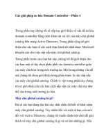
While still using the Line tool, click the peak point, 1.
tap the right arrow key to lock the red direction,
and click the roof face (Figure 5-39).
You can Shift-lock a constraint even when a line 2.
starts out in the opposite direction. Start the next
line where indicated in Figure 5-40, and move the
cursor away from the house in the red direction.
Press and hold Shift.
Click the roof face, and the line snaps back in the 3.
correct direction (Figure 5-41).
Figure 5-39
Figure 5-40
Figure 5-41
Add two more lines to complete the two faces on 4.
one side of the dormer (Figure 5-42).
Figure 5-42
120
|
Chapter 5: Roofs: Constraints and Inferences
You could use the same method to complete the 5.
other side of the dormer, but if the dormer has all
its sides, you’d need to hide a face in order to cut
the hole in the roof. The bottom face of the dormer
should be completed so that the roof hole can be
cut first; then the remaining sides of the dormer
can be created. Start the line at the back of the peak
and hover over the corner indicated in Figure 5-43.
Figure 5-43
Move in the red direction then hold Shift while 6.
clicking the roof face (Figure 5-44). This is another
way to use a double constraint.
Figure 5-44
Complete the edges for the hole in the roof and 7.
erase the hole face (Figure 5-45).
Figure 5-45
Then complete the dormer sides (Figure 5-46).8.
Figure 5-46
Creating Dormers
|
121
Create finishing touches
Now you can add a window in the dormer and make
copies of it.
The first step is to add a frame to the dormer face, 1.
to match the frames of the windows below it. Ac-
tivate Offset and click the dormer face on its right
edge (indicated by the red arrow in Figure 5-47).
Then complete the offset by clicking on the inner-
right edge of the window below (yellow arrow).
This makes the dormer frame the same thickness as
the window frame.
Figure 5-47
For the glass, start the Push/Pull on the inner 2.
dormer face and end it by clicking the glass below
(Figure 5-48).
As you should always do when something in 3.
your model will repeat, make the entire dormer a
component.
Figure 5-48
Copy the dormer, constraining it to the green direc-4.
tion by using either the left arrow key or the Shift-
locking method (Figure 5-49).
Figure 5-49
To copy both dormers to the other side, copy them 5.
in the red direction into some blank space (Figure
5-50).
There are a few ways to flip objects, but I prefer 6.
using the Scale tool. A scale value of –1 makes an
“inside-out” copy.
Note
Using Scale to flip components is a great way to create sym-
metric objects. This will be shown in Recipe 7.11.
Figure 5-50
122
|
Chapter 5: Roofs: Constraints and Inferences
To move the copied dormers back to the roof, move 7.
them by a peak point, lock the red direction, and
click the roof face (Figure 5-51).
Figure 5-51
Use Intersect with Model to cut roof holes, and 8.
your four dormers are complete (Figure 5-52).
Figure 5-52
Working with Roof Intersections5.3
Problem
You have roofs of different heights or slopes on various parts of a building, and you want to
resolve the ridge and valley lines where the roofs meet.
Solution
Create new edges at the intersections by using double constraints.
Discussion
When you have roof faces of different slopes and heights, start resolving their intersections by
thinking about the existing edges and faces that the new edges must meet. It is also important
to understand which face will meet new ridge lines. By knowing which ridge line is higher, you
can figure out where roof volume needs to be added and where it needs to be removed. After
you establish this, you can apply double constraints to define the new edges.
Using double constraints to resolve intersecting roofs will be shown by two examples. In the
first example, one roof meets roofs of different heights on either side, in the middle of the other
roofs (not at corners). In the second example, roofs of different heights meet at corners.
Working with Roof Intersections
|
123
Example 1: End-Middle Intersections
In this example, you must contend with three roofs of
alternating directions, each with a different height and
slope. The middle roof meets the outer roofs in the
middle, not at their corners. Edges are needed at each
end of the middle roof, to resolve the roof to its neigh-
boring faces.
Download my 1. Roof End Middle model (shown in
Figure 5-53) from the 3D Warehouse. The green
roof in the middle is perpendicular to the roofs on
either side and meets the other roofs in the middle
(not at corners).
Want to Create This Model Yourself?
In Top1. view, draw three rectangles for the footprint.
The outer rectangles should have longer vertical edg-
es, and the middle one should have longer horizontal
edges.
Rotate all three rectangles slightly. This removes the 2.
ability to use red and green directions (just to make
this a little harder).
Pull up the yellow rectangle higher than the green, 3.
and the green higher than the purple.
Add ridge lines across each top, and move them up so 4.
that the purple peak is the highest, followed by green,
followed by yellow.
Resolve the green-purple intersection first. Start 2.
a line at the closest ridge point of the green roof,
indicated in Figure 5-54. Then hover over the green
ridge line.
Press and hold Shift to lock the direction of this 3.
edge. Then click the closest purple roof face. This
extends the green ridge line until it meets the
purple roof.
The next line will continue from the previous line 4.
you created. Hover over the edge indicated in Fig-
ure 5-55.
Hold Shift and click the same purple face. This ex-5.
tends the edge you hovered over, to meet the purple
roof.
Add two more lines to complete the extension of 6.
the roof face and the wall face (Figure 5-56).
Figure 5-53
Figure 5-54
Figure 5-55
Figure 5-56
124
|
Chapter 5: Roofs: Constraints and Inferences
Add the same edges on the other side of the green 7.
roof and erase extra lines. The intersection of the
green and purple roofs is shown in Figure 5-57.
Figure 5-57
Now the green-yellow intersection will be resolved. 8.
Because the green ridge is higher than the yellow
ridge, the far yellow face will need to have material
added to it. Start a line as before, from the green
ridge endpoint indicated in Figure 5-58, and then
hover over the green ridge.
Figure 5-58
Shift-lock this line to the far yellow face. Depending 9.
on your roof slopes, the line might end somewhere
past the current ridge line or instead end some-
where within the line (as in this example, shown in
Figure 5-59).
Figure 5-59
Start a new line at this new endpoint. Then hover 10.
over either green roof face and hold Shift. Con-
strain this line to end on the yellow ridge line by
clicking the yellow ridge line (Figure 5-60).
Figure 5-60