Learning AutoCAD 2010, Volume 1 phần 3 docx
Bạn đang xem bản rút gọn của tài liệu. Xem và tải ngay bản đầy đủ của tài liệu tại đây (7.5 MB, 46 trang )
Lesson: Creating Basic Objects ■ 79
Undo and Redo Commands
Use the Undo command to step back through every action you made, including pan and zoom. Use
the Redo command to step forward through those actions again. These commands are conveniently
located on the Quick Access toolbar. You can Undo at any point in the drawing session, even within
some of the draw and modify commands. However you can only Redo immediately after an Undo
Command.
You may also type the Undo command at the Command line. Enter U and press ENTER. If you continue
to press ENTER, the Undo command will be repeated. If you enter the entire word UNDO at the
Command line and press ENTER, you will see a list of Undo options at the Command line prompt.
If you are working in the AutoCAD Classic workspace the Undo and Redo buttons include down arrows
that reveal lists which you can choose to undo or redo up to a selected item or step.
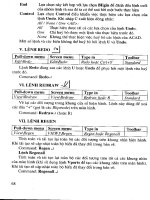
Command Access
Undo
Command Line: U, UNDO
Menu Bar: Edit > Undo
Quick Access Toolbar: Undo
80 ■ Chapter 2: Creating Basic Drawings
Command Access
Redo
Command Line: REDO
Menu Bar: Edit > Redo
Quick Access Toolbar: Redo
Command Options
The following options are available only when you type the entire word UNDO at the Command Line.
Right-click to access the shortcut menu or type the capitalized letter of the option.
Option
Description
Auto
Groups all actions of a single command, making them reversible with a single U
command.
Control
Limits or turns off Undo.
Begin, End
Groups a sequence of actions into a set. After you use the Begin option, all
subsequent actions become part of this set until you use the End option.
Mark
Places a mark in the undo information. If you use the Back option, all sequences are
undone to the mark.
Back
Undoes all work to the first mark that is encountered. If there are no marks placed in
the undo information, the following prompt appears:
This will undo everything. OK? <Y>
If you continue, all steps in the drawing are undone to the beginning of the drawing
session.
The Mredo command is similar to the expanded UNDO command in that it offers
other options to redo, such as the last step of all of the prior Undo operations.
Lesson: Creating Basic Objects ■ 81
Procedure: Using Undo and Redo
The following steps give an overview of how to use the Undo and Redo commands in the drawing.
1.
On the Quick Access Toolbar, click Undo (1), or enter U in the command line.
2.
Each time you select the Undo button a single operation is undone. If you entered U in the command
line, you can continue to press ENTER to repeat the Undo command.
3.
To Redo an operation, click Redo (2) in the Quick Access toolbar or type REDO immediately following
an undo operation.
4.
Continue to select Redo until the drawing is returned to the desired state.
5.
You can access the Undo or Redo lists on the Standard Toolbar to highlight the steps to undo or redo.
Undo and Redo Guidelines
■ Undo information is only saved in the current session of the drawing. If you exit the drawing and
reopen it, you cannot undo steps that were done in the previous session.
■ The Redo command is only available immediately after an Undo operation.
■ You can undo all the way back to the beginning of the drawing.
■ Enter UNDO on the command line to view advanced Undo options.
■ Enter MREDO on the command line to view advanced Redo options.
■ If you have multiple drawings open at once, each drawing contains separate undo information and,
as a result, you can use the Undo command independently within each drawing.
82 ■ Chapter 2: Creating Basic Drawings
Practice Exercise: Undo and Redo Commands
Most of the time you use Undo and Redo in single
steps. In this exercise, you practice using the Undo
and Redo commands and some of the Undo options.
1.
Begin a new, blank drawing.
2.
In the Select Template dialog box, choose the
acad template.
3.
Draw some circles and then undo them:
■ On the command line, enter C. Press
ENTER. Draw five circles.
■ On the Quick Access toolbar, click Undo
until all five circles are gone.
■ On the Quick Access toolbar, click Redo
repeatedly to bring all five circles back.
4.
Draw some lines. Practice using the Undo
command within the line command.
■ On the command line, enter L and press
ENTER. Draw several continuous line
segments. Press ENTER to complete the
Line command.
■ On the command line, enter U. Press
ENTER. Notice that all of the line segments
are undone.
■ On the command line, enter L. Press
ENTER. Draw several continuous line
segments. Do not exit the line command.
Right-click and select Undo from the
shortcut menu.
■ Notice that the last line segment is
undone. Right-click and select Undo again
from the shortcut menu. Do not exit the
line command. Continue to draw line
segments. Press ENTER to complete the
Line command.
Lesson: Creating Basic Objects ■ 83
5.
Practice using the Undo options, BEgin and
Back.
■ On the command line, enter UNDO. Press
ENTER.
■ Enter BE (for BEgin). Press ENTER.
■ On the command line, enter L. Press
ENTER. Draw some continuous line
segments. Press ENTER to complete the
line command.
■ Draw some circles, rectangles and arcs.
■ With the command line blank, press the
up arrow on the keyboard to scroll to the
UNDO command. If you pass it, use the
down arrow to scroll back. When Undo is
in the command line, press ENTER.
■ Enter B (for Back). Press ENTER.
■ This should undo the lines that you
created.
84 ■ Chapter 2: Creating Basic Drawings
Rectangle Command
Use the Rectangle command to create rectangular objects. A single polyline object is created with
this command. The simplest method for creating a rectangle is to specify the first corner, then the
opposite corner. Other options for creating the rectangle include the Area, Dimension, and Rotation
options.
This illustration shows a rectangle with the point used to create it specified.
Command Access
Rectangle
Command Line: RECTANGLE, REC
Menu Bar: Draw > Rectangle
Ribbon: Home tab > Draw panel > Rectangle
Lesson: Creating Basic Objects ■ 85
Command Options
These Rectangle options are available after you have selected the first point for the rectangle. Right-
click to select from the shortcut menu or type the capitalized letter at the Command line.
Option
Description
Area
Use this option to create a rectangle based on its area and the distance of one side,
whether length or width.
Dimensions
Use this option to manually enter the length and width of the rectangle.
Rotation
Use this option to specify a rotation angle for the rectangle.
When you use the Distance or Area options to specify the rectangle size, the Length
prompt refers to the horizontal distance, while the Width prompt refers to the vertical
distance. If the rectangle is being rotated, Length refers to the distance along the rotation
angle, while Width refers to the distance perpendicular to the rotation angle.
Rectangle Command Guidelines
■ The Rectangle command generates polyline objects.
■ Because rectangles are polylines, selecting any segment selects the entire rectangle.
■ The simplest method for drawing a rectangle is to specify the first corner, then the opposite
corner using relative x,y coordinates. Example: after selecting the fist point, type @4,5 to make a
rectangle that is 4 x 5.
■ Rectangles can be initiated from any corner. After selecting the first point, if you type @-4,-5 you
will make a rectangle that is located below and to the left of the first point selected.
When using the dimension input option, you need to click to select an orientation.
After you enter the length and width values, move your cursor up and down or
left and right to view the available orientations. When the orientation you want is
displayed, click to create the rectangle.
86 ■ Chapter 2: Creating Basic Drawings
Practice Exercise: Rectangle Command
Practice drawing rectangles using coordinate
dimensions.
Practice other Rectangle options. Adjust your display
as you work
using the Zoom and Pan Realtime commands.
1.
Open a new drawing.
2.
Check that the Dynamic Input option on the
status bar is not selected.
3.
To draw Rectangles using relative coordinates
@x,y:
■ On the ribbon, click Home tab > Draw
panel > Rectangle.
■ To specify the first corner, click anywhere
in the drawing window.
■ At Specify first corner point prompt, enter
@4,5 and press ENTER.
■ Notice that a rectangle was drawn up and
to the right of the first point selected. If
this did not happen, then you forgot to
enter @ before the x,y coordinates. Try
again.
4.
Continue to draw Rectangles using relative
coordinates @x,y:
■ On the Home tab, click Draw panel >
Rectangle. Click the first corner anywhere
in the drawing window.
■ Enter the relative coordinates @x,y and
press ENTER to make rectangles with the
following dimensions:
■ 6 x 7 (enter @6,7)
■ 7 x 6 (enter @7,6)
■ 9 x 9 (enter @9,9)
5.
Turn on the Dynamic Input option on the
status bar.
6.
To draw a rectangle 7 x 10:
■ On the Home tab, click Draw panel >
Rectangle. Click the first corner anywhere
in the drawing window.
■ Enter 7,10 (do not enter the @ symbol)
and press ENTER.
■ A rectangle should have been made up and
to the right of the start point. If not, check
to be sure that Dynamic Input is on in the
Status Bar and try again.
■ Press F2.
■ Observe that @ symbol was automatically
added to the coordinate making it relative
to the last point you selected.
■ Practice making the following rectangles:
■ 2 x 2 (enter 2,2)
■ 4 x 6 (enter 4,6)
7.
To use the Rectangle > Area option:
■ On the Home tab, click Draw panel >
Rectangle.
■ Click a point anywhere in the drawing
window for the first corner.
■ Enter A (for Area) and press ENTER.
■ Enter 35 for the area and press ENTER.
■ To specify the Length, press ENTER to
accept the default if [Length] is already
in brackets. Otherwise, enter L and press
ENTER.
■ Enter 7 for the rectangle length and press
ENTER.
Lesson: Creating Basic Objects ■ 87
Polygon Command
Use the Polygon command to create regular polygon geometry by specifying the center point and
radius of an imaginary circle, or the start point and endpoint of one of the polygon edges. Regardless
of the method you choose to define the polygon, all of its sides are equal in length.
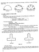
The default method for creating polygons is to specify a center point and radius. When you choose this
method, you must choose either the Inscribed or Circumscribed option. Depending on the option you
choose, the size of the polygon is calculated as shown in the following image.
Command Access
Polygon
Command Line: POLYGON, POL
Menu Bar: Draw > Polygon
Ribbon: Home tab > extended Draw panel > Polygon
88 ■ Chapter 2: Creating Basic Drawings
Command Options
The following Polygon command options are available from the shortcut menu (right-click) or the
Command line. Type the capitalized letter(s) of the option.
Option
Description
Enter number of
sides
Polygons can have between 3 and 1024 sides.
Specify center of
polygon
(default) Note that while you may pick any point for the center of a polygon, once it
is made you will not be able to simply snap to its center.
Inscribed in circle
Draws a polygon within a designated radius.
Circumscribed
about circle
Draws a polygon outside of a designated radius.
Edge
Draws a polygon based on the number of sides and the length of a specified edge.
Polygon Command Guidelines
■ Polygons can have between 3 and 1024 sides.
■ Regardless of the number of sides you choose, all sides are equal in length.
■ The Polygon command creates polyline objects.
■ Polygon is a good tool for creating balloons and other types of annotation symbols.
Lesson: Creating Basic Objects ■ 89
Practice Exercise: Polygon Command
Use the Polygon command to draw a 6-sided
polygon that is inscribed about a circle, one that is
circumscribed about a circle, and one that has an
edge length of 1. First, draw two circles with a radius
of 1.5, then draw the polygons.
Note: Although you will draw the inscribed and
circumscribed polygons inside a circle, it is only to
compare the two options. It is not necessary to draw
a circle first to make a polygon.
1.
Open a new drawing using the acad.dwt
template.
2.
Click the following status bar options so that
they are on:
■ Polar tracking
■ Object snap
■ Object snap tracking
On the status bar, right-click Object Snap and
click the Center snap mode so that it is also on.
3.
To draw a polygon that is inscribed in a circle,
as shown in example 1:
■ On the ribbon, click Home tab > Draw panel
> Polygon.
■ Enter 6 for the number of polygon sides.
■ Click the center of the circle for the center
of the polygon. If object snap is on and
center mode is selected, you will see the
center snap indicator, as shown below.
■ Enter I (for Inscribed). Press ENTER.
■ To specify the radius of the polygon circle,
enter 1.5. Press ENTER.
90 ■ Chapter 2: Creating Basic Drawings
4.
To draw a polygon that is circumscribed about
a circle, as shown in example 2:
■ On the Home tab, click Draw panel >
Polygon.
■ Enter 6 for the number of polygon sides.
■ Click the center of the circle for the center
of the polygon. Click when you see the
circle's center object snap.
■ Enter C (for Circumscribed). Press ENTER.
■ To specify the radius of the circle, enter 1.5.
Press ENTER.
5.
To draw a polygon using the Edge option, as
shown in example 3:
■ On the Home tab, click Draw panel >
Polygon.
■ Enter 6 for the number of polygon sides.
■ Enter E (for Edge). Press ENTER.
■ Click anywhere in the drawing window to
specify the first endpoint of the edge.
■ Drag the cursor and notice that with
PolarSnap on you can specify the polar
angle of the edge. Enter 1. Press ENTER.
Lesson: Creating Basic Objects ■ 91
Exercise: Create Basic Objects
In this exercise, you create a simple mechanical bracket using the basic geometry commands such as Line,
Circle, Arc, Rectangle, and Polygon.
The completed exercise
Completing the Exercise
To complete the exercise, follow the
steps in this book or in the onscreen
exercise. In the onscreen list of
chapters and exercises, click Chapter 2:
Creating Basic Drawings. Click Exercise:
Create Basic Objects.
Practice Creating Basic Objects: Part 1
In this part of the exercise, you begin to draw the
front view of the bracket, beginning at point (1) and
ending at point (2). Then, you resume drawing from
point (1) to point (3).
1.
Open M_Create-Basic-Objects.dwg.
2.
On the status bar, make sure the following
settings are on:
■ Polar tracking
■ Object snap
■ Object snap tracking
■ Dynamic input
3.
To begin the line at point (1):
■ On the Home tab, click Draw panel > Line.
■ Enter 100, 50. Press ENTER.
■ Enter 100. Press TAB.
■ Enter 0
The values should appear in the Input
interface as shown in the following
image.Note: The values should appear
in the Input interface as shown in the
following image.
■ Click to create the line.
92 ■ Chapter 2: Creating Basic Drawings
4.
To draw a second line perpendicular to the
first:
■ Drag the cursor upwards and enter 100.
Press TAB.
■ Make sure the angle field displays 90
degrees, then click to draw the line.
5.
To draw another line:
■ Drag the cursor to the left making sure that
the angle field displays 180 degrees.
■ Enter 25. Press ENTER.
Note: Using direct distance entry in
combination with dynamic input provides
you with optimal flexibility in creating your
drawings.
6.
To draw another line:
■ Drag the cursor downward making sure
that the angle field displays 90 degrees.
■ Enter 50. Press ENTER.
■ Press ENTER again to finish the line
command at point (2).
7.
To undo all the lines that you just drew:
■ On the Quick Access toolbar, click Undo.
■ Notice that all of the lines that you created
in the previous steps are removed.
Lesson: Creating Basic Objects ■ 93
8.
To redo the lines:
■ On the Quick Access toolbar, click Redo.
■ Notice that all of the lines removed with
the Undo command are returned.
9.
To draw a line using object snaps:
Note: Object snaps are points on objects
which enable you to accurately position other
objects. They are covered in detail in another
lesson.
■ On the Home tab, click Draw panel > Line.
■ As you approach the endpoint of the line,
the endpoint object snap marker should
appear.
■ Click to select the endpoint of the line.
10.
To draw a line perpendicular to the last:
■ Drag the cursor upward making sure that
the angle field displays 90 degrees.
■ Enter 100. Press ENTER.
11.
To draw a line and correct a mistake using the
Undo command:
■ Drag the cursor to the right making sure
the angle field displays 0 degrees.
■ Enter 35. Press ENTER.
■ Right-click near your last point. Click Undo.
■ Because you are still in the Line command,
only the last line segment that you drew is
removed.
■ Drag the cursor to the right again, making
sure that the angle field displays 0 degrees.
■ Enter 25. Press ENTER.
94 ■ Chapter 2: Creating Basic Drawings
12.
To draw a line perpendicular to the last:
■ Drag the cursor downward, making sure
that the angle field displays 90 degrees.
■ Enter 50. Press ENTER.
13.
Press ENTER to exit the Line command.
Proceed to part two of this exercise.
Practice Creating Basic Objects: Part 2
In this part of the exercise, you draw the arc (1) in the
front view of the bracket and add the side view (2).
You then place the circles and polygons (3) in the four
corners of the front view.
1.
Now draw the arc:
■ On the Home tab, click Draw panel > Arc.
■ Select the endpoint of the previous line.
■ Press DOWN ARROW and click End on the
shortcut menu.
2.
Select the endpoint on the right side of the
opening.
Lesson: Creating Basic Objects ■ 95
3.
To finish the arc:
■ Drag the cursor to the left, making sure
that the angle field displays 180 degrees.
■ Enter 25. Press ENTER.
■ Your drawing should now appear as shown.
4.
Click File menu > Save.
Tip: You should develop a habit of saving files
often.
5.
To draw a rectangle:
■ On the Home tab, click Draw panel >
Rectangle.
■ Touch (DO NOT CLICK) point (1) as
indicated in the following image.
■ Drag the cursor to the right. The extension
object snap draws a dashed extension line.
■ Click near point (2).
6.
To position the rectangle:
■ Right-click near your first point and select
Dimensions on the shortcut menu.
Note: This specifies the Dimension option of
the Rectangle command.
■ For the length, enter 25. Press ENTER.
■ For the width, enter 100. Press ENTER.
■ Click in the upper right of the drawing to
position the rectangle.
Your drawing should now appear as shown in
the following image.
96 ■ Chapter 2: Creating Basic Drawings
7.
To draw a circle:
■ On the Home tab, click Draw panel > Circle.
■ Enter 112.50,65. Press ENTER.
■ In the Dynamic Input Radius field, enter
7.5. Press ENTER.
8.
To draw a rectangle:
■ On the Home tab, click Draw panel >
Rectangle.
■ Select the center point of the circle (1).
Note: The object snap marker should appear as
you approach the center of the circle.
■ Drag the cursor to the upper right (2) and
enter 75,70. Press ENTER.
■ Your drawing should appear as shown.
9.
To draw three more circles as shown:
■ On the Home tab, click Draw panel > Circle.
■ Create three circles, each with a 7.5 unit
radius, using the corners of the rectangles
as center points.
Tip: The software stores the last radius that
you entered. If the command prompt is reading
<7.500> you can press ENTER to reuse that
value for the radius.
10.
On the Home tab, click Modify panel > Erase.
Select the rectangle that was used to position
the circles. Press ENTER.
11.
To draw a polygon circumscribing the top left
circle:
■ On the Home tab, click Draw panel >
Polygon.
■ When prompted for the number of sides,
enter 6.
■ Select the center of the top left circle.
■ In the Dynamic Input menu, select
Circumscribed About Circle.
■ For the radius, enter 8. Press ENTER.
Lesson: Creating Basic Objects ■ 97
12.
To create three similar polygons circumscribing
the other circles:
■ Press ENTER to repeat the Polygon
command.
■ Create three additional polygons on the
remaining circles as shown.
13.
Close all files. Do not save.
98 ■ Chapter 2: Creating Basic Drawings
Lesson: Using Object Snaps
In this lesson, you learn what object snaps are, why they are important, and how to use them
effectively in your drawing. You will be able to explain what object snaps are including the difference
between running object snaps and object snap overrides. You will also be able to use objects snaps to
select snap points in the drawing.
You will use object snaps for all drawing and most editing operations. Using object snaps is the best
way to ensure the accuracy of all of your objects.
In the following illustration, the image on the left shows a door placement that used an object snap to
place the door. The image on the right shows what the door placement looks like if you do not use an
object snap.
Objectives
After completing this lesson, you will be able to:
■ Explain what object snaps are and why they are used.
■ State the difference between running object snaps and object snap overrides and identify the
different Object Snap modes.
■ Use running object snaps and object snap overrides to select snap points in the drawing.
Lesson: Using Object Snaps ■ 99
About Object Snap
Every object you create has various selectable points that you can use to position other objects. Every
time you create an object you are required to specify a point or location. It is critical that these points
be defined accurately if you expect your drawing to be accurate.
Object Snaps Defined
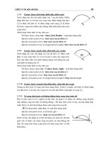
The following image shows three of the most basic types of objects that you can create: a line, a circle,
and an arc. In this example, the line has two unique snap types with three possible locations that you
can select; the circle has two unique snap types with five possible locations that you can select; the arc
has three unique snap types with four possible locations that you can select.
1. Endpoint
2. Midpoint
3. Center point
4. Quadrant
Object snaps exist for each of the previously mentioned points and more. You use them to select those
points accurately. Attempting to accurately select these points without using object snaps would be
very time-consuming and inaccurate.
Effect of Using Object Snaps
In the following image, the smaller circle needs to be concentric within the larger circle. By using the
Center object snap, you can place the smaller circle precisely in the center of the larger circle.
By examining each circle's coordinates, you can verify that they both share the same center point.
100 ■ Chapter 2: Creating Basic Drawings
Effect of Not Using Object Snaps
In the following image, the user attempted to create the vertical line at the endpoint of the horizontal
line without using objects snaps. Under normal viewing circumstances, the lines appear to be
connected correctly; however, after zooming in to the geometry, you can see that the lines are not
connected at the endpoints.
Object Snap Key Points
■ Using object snaps to place objects in relation to other objects in the drawing is critical for
accuracy.
■ Every object you can create contains at least one point that is selectable with an object snap.
Object Snaps
You can access object snaps using several different methods. Running object snaps are generally set
and then turned on or off, while object snap overrides represent a one-time use of the selected object
snap.
■ Running object snaps refer to object snaps that are set and available when the Osnap setting is on.
■ Object snap overrides refer to an object snap that you select manually via the toolbar, shortcut
menu, or command line. The object snap remains in effect until you specify the next point.
Running Object Snap
If you need to use the same object snap repeatedly, you can set it as a running object snap, which
means it stays on until you turn it off. For example, you might set the object snap to center if you need
to connect the centers of a series of circles with a line. This feature increases speed and accuracy.
Another feature of running object snap is that multiple object snaps can be on at the same time.
Lesson: Using Object Snaps ■ 101
Running Object Snap
Command Line: OSNAP
Menu Bar: Tools > Drafting Settings > Object Snap Tab
Keyboard Shortcut: F3
Toolbar: Object Snap
Status Bar: Object Snap
Object Snap Settings
The quickest way to turn Running Object Snap on or off is from the Status bar button (1). If you right-
click on this button, you can select Settings (2) to change the object snap options in the Drafting
Settings dialog box (shown below). You can also select the snap modes from the shortcut menu. A
selected object snap mode will be highlighted (3).
Notice that information in the Object Snap tab of the Drafting Settings dialog box is similar to the
shortcut menu shown above.
102 ■ Chapter 2: Creating Basic Drawings
Next to each available object snap is an icon referred to as the AutoSnap marker. If AutoSnap is turned
on, the marker appears whenever you move the cursor over a snap point. Press the Tab key to cycle
through the available snap points. Never turn all the object snap modes on at once. It is better to have
several object snaps chosen (such as Endpoint, Midpoint and Intersection) and go back to add others
as needed or use the object snap override.
When Are Object Snaps Available?
You can specify an object snap whenever the software prompts for a point.
Lesson: Using Object Snaps ■ 103
Object Snap Override
Object Snap override means that the snap stays in effect until you specify the next point. You are in
snap override mode if you click an object snap from the shortcut menu or the object snap toolbar
before selecting the specified point.
Object Snap Toolbar
Command Line: While being prompted to select a point, enter the first 3 letters of the object snap
and press ENTER (i.e. MID, INT, NEA)
Menu Browser: Tools > Toolbars > ACAD > Object Snap
Toolbar: Object Snap (access from the Menu Browser)
Shortcut Menu: SHIFT + right-click in the drawing window