Learning AutoCAD 2010, Volume 1 phần 8 pot
Bạn đang xem bản rút gọn của tài liệu. Xem và tải ngay bản đầy đủ của tài liệu tại đây (7.5 MB, 46 trang )
Lesson: Using the Properties Palette ■ 309
Procedure: Using the Properties Palette to Change Object Properties
The following steps give an overview of using the Properties palette to change object properties.
1.
On the ribbon, click Home tab > Properties panel > Dialog Box Launcher > Properties or press CTRL+1.
2.
Select the objects to adjust properties for.
3.
You can change any value in a read-write field and all changes occur in real time.
4.
Press ESC to cancel the object selection. The Properties palette remains open.
Key Points for Using the Properties Palette
■ The Properties palette differs from a traditional dialog box interface in that it can remain open
while you are using other commands.
■ Other methods are available for editing an object's properties, but the Properties palette provides
a common interface for changes to different object types and to the properties of multiple objects
simultaneously.
■ Click the Auto-hide icon on the Properties palette (shown in the following illustration) to make the
palette collapse when the cursor moves away from it.
310 ■ Chapter 4: Drawing Organization and Inquiry Commands
Exercise: Manipulate Object Properties
In this exercise, you learn how the Properties palette
functions. When you have completed the exercise,
you will be able to effectively manipulate objects and
their properties using the Properties palette.
The completed exercise
Completing the Exercise
To complete the exercise, follow the
steps in this book or in the onscreen
exercise. In the onscreen list of
chapters and exercises, click Chapter
4: Drawing Organization and Inquiry
Commands. Click Exercise: Manipulate
Object Properties.
1.
Open C_Properties-Palette.dwg.
2.
To open the Properties palette, press CTRL+1.
Note: If the Properties palette is already
open, CTRL+1 will close it. You can also access
the Properties palette by double-clicking an
object in the drawing. This either opens the
Properties palette if it is not currently open,
expands the palette if Auto-hide is set, sets the
focus to the palette if it was already open, or
launches the PEDIT command if you double-
click a polyline.
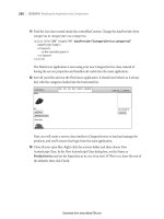
3.
Click the Auto-hide button in the upper left
corner of the Properties palette as shown in
the image.
Lesson: Using the Properties Palette ■ 311
This causes the Properties palette to expand
when you move the mouse over it and
contract when the mouse moves away. You can
also dock the palette by dragging it to the edge
of the application window.
4.
Change object properties using the palette:
■ Select all of the objects in the drawing.
■ On the Properties palette, change the color
and linetype to ByLayer.
■ Press ESC to clear the selection and notice
the change in color.
5.
Zoom in to the area shown.
6.
To change the color of selected polylines:
■ Select all of the geometry in the window.
■ On the Properties palette, select Polyline
from the Object Type list.
■ Select the Color property and set it to Blue.
■ Press ESC and notice that all polylines in
the selection are now blue.
7.
To change the display of the drawing:
■ Zoom to the extents of the drawing.
■ Zoom to the area shown in the image.
312 ■ Chapter 4: Drawing Organization and Inquiry Commands
8.
To select objects to change:
■ On the Home tab, click Layers panel >
Layer. Turn off Layer 1 in the Layer list.
■ Select the large circle in the view.
9.
To change the diameter of the circle using the
palette:
■ On the Properties palette, change the
Diameter to 64.
■ Press ENTER.
The diameter changes.
10.
Use a crossing window selection to select
more objects in the view.
11.
To change object properties by filtering:
■ Use the Object List at the top of the
Properties palette to filter just the circle
objects.
The properties common to all circles appear in
the Properties palette.
■ Change the diameter to 32 units.
■ Press ENTER.
The diameters of all circles in the selected view
change to 32.
12.
Close all files. Do not save.
Lesson: Using Linetypes ■ 313
Lesson: Using Linetypes
This lesson describes how to use linetypes in your drawings. After completing this lesson, you will be
able to describe linetypes and how they are used in a drawing and use the Linetype Manager to add
linetypes to your drawing.
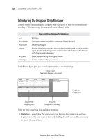
Linetypes are used to distinguish objects in the drawing from one another. You can use them to
represent hidden geometry in a specific view, to show centerlines for dimensioning, or perhaps just to
add clarity to the drawing.
For example, the following illustration shows a solid linetype used for geometry and a centerline
linetype used for centerlines for dimensioning. The dashed linetype indicates hidden geometry.
Objectives
After completing this lesson, you will be able to:
■ Describe linetypes and how they are used in a drawing.
■ Use the Linetype Manager to add linetypes to your drawing.
314 ■ Chapter 4: Drawing Organization and Inquiry Commands
About Linetypes
In a typical drawing, you find linetypes associated with many objects. While the specific linetypes
used may vary from one discipline to another, the concept of using linetypes remains consistent. They
are always used to distinguish objects from one another and to make the drawing easier to read and
understand.
The following illustration contains continuous, hidden, and center linetypes. Each of these linetypes
have meaning within the discipline in which they are used.
Linetypes Defined
Linetypes are an attribute of an object that determines how it looks. The linetype helps to distinguish
oneobject from another in adesign. For example, a hot water linecould berepresented by the HW
linetype and a gas line in a building could be represented by the GASlinetype.
This image shows common linetypes used in drafting and design.
Lesson: Using Linetypes ■ 315
Linetype Examples
In the following image, you see two pieces of steel overlapping one another. It is impossible to tell
which object lies on top of the other.
This second image uses hidden lines on the vertical steel object to show you that it lies beneath the
horizontal piece of steel.
Linetype Key Points
■ Linetypes are used to distinguish objects from one another.
■ Linetypes add visual clarity to the drawing.
316 ■ Chapter 4: Drawing Organization and Inquiry Commands
Adding Linetypes to Your Drawing
To add linetypes to your drawing, you generally assign the linetype to layers and then create objects
on the appropriate layers. The object's linetype can be set to ByLayer, which means the object
assumes the linetype of the layer.
By default, the only linetype available in the drawing is Continuous. To use additional linetypes, you
must load them into the drawing. The primary method for adding linetypes to the drawing is with the
Linetype Manager.
Command Access
Linetype Manager
Command Line: LINETYPE
Ribbon: Home tab > Properties panel > Linetype list > Other
Menu Bar: Format > Linetype
Lesson: Using Linetypes ■ 317
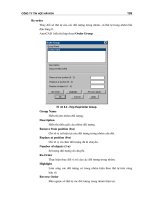
About the Linetype Manager
The Linetype Manager dialog box displays all of the linetypes that are currently loaded in the drawing.
To load additional linetypes, click Load. To delete linetypes, select the linetype and click Delete. You
cannot delete a linetype if it is currently being referenced by other objects in the drawing.
318 ■ Chapter 4: Drawing Organization and Inquiry Commands
Loading Linetypes
When you select Load from the Linetype Manager dialog box a list of linetypes provided by AutoCAD
appears that lets you add additional linetypes to the drawing. You can scroll through the list and select
the desired linetypes.
Loading Linetypes from the Layer Property Manager
You can also add linetypes to a drawing from the Layer Properties Manager. Click to
assign the linetype to a layer. If the linetype is not available in the Select Linetype
dialog box, click Load to load the linetype using the Load or Reload Linetypes dialog
box.
Controlling Linetype Scale
Depending on the size of the objects in your drawing, you may have to adjust the linetype scale in
order for the lines to appear correctly. For example, to see the gaps in a centerline that is 12 units
long, you would set your linetype scale to 1.0, but to see the gaps correctly in a centerline that is 240
units long, you would set your linetype scale to 10.0.
In the following illustration, both lines are center linetypes, but the lower line appears with a more
dense pattern as a result of a smaller linetype scale.
Lesson: Using Linetypes ■ 319
You can control linetype scale in the drawing using two different methods.
■ LTSCALE: This is a global linetype scale factor that affects all of the objects that use linetypes in the
drawing. To change the global linetype scale, on the Command line, enter LTSCALE and then enter
a positive number. The default scale factor is set to 1.
■ Linetype Scale property: You can set the linetype scale factor for selected objects. Double-click
the object to access the Properties palette (or right-click and select Properties from the shortcut
menu). Enter a new value in the Linetype Scale property field. The Linetype Scale property works
in combination with the global linetype scale factor for the drawing. For example, if the global
linetype scale factor is set to 2 and the linetype scale property is set to 0.5, the net result is a
linetype scale factor of 1 for the selected object.
Properties Palette
Procedure: Adding Linetypes to a Drawings
The following steps give an overview of adding linetypes to a drawing.
1.
On the ribbon, click Home tab > Properties panel > Linetype list > Other.
320 ■ Chapter 4: Drawing Organization and Inquiry Commands
2.
In the Linetype Manager, click Load.
3.
In the Load or Reload Linetypes dialog box, select the linetypes. Click OK.
Press the Shift or Ctrl key to select more than one linetype.
4.
The selected linetypes appear in the Linetype Manager. Click OK.
5.
The linetypes are now available to apply to layers or individual objects.
Lesson: Using Linetypes ■ 321
Linetype Management Guidelines
■ By default, a blank drawing will contain only one linetype, the continuous linetype.
■ Add only the linetypes that you need for your drawing.
■ Delete linetypes that are not being referenced or used from the Linetype Manager dialog box or
with the PURGE command.
■ A linetype that is being referenced or used cannot be deleted.
■ To use other linetypes, you must load them into the drawing first and then apply them to the
object or layer.
■ Control linetype scale with the LTSCALE command. For example, an LT scale of 24 will multiply the
size of all of the linetypes in a drawing by 24.
■ Set the linetype scale of individual objects only when necessary using the Properties palette.
Linetype scale settings made to individual objects are multiplied by the overall LTSCALE factor.
■ Certain linetypes are available at and 2 times the normal size. Example: HIDDEN, HIDDEN2 (.5x)
and HIDDENX2 (2x).
■ By default, all object properties are drawn in the ByLayer mode, so objects will take on the
property settings of the current layer. You can override the default mode by selecting a specific
linetype from the Linetype list on the Properties panel.
322 ■ Chapter 4: Drawing Organization and Inquiry Commands
Practice Exercise: Add Linetypes to Your Drawing
In this practice exercise, you draw a simple object.
You add the HIDDEN linetype to the drawing, apply
it to the object that you create, and then change the
LTSCALE.
1.
Begin a new drawing and make a rectangle.
2.
To access the Linetype Manager:
■ On the Home tab, click Properties panel >
Linetype list > Other.
3.
To load the linetype:
■ In the Linetype Manager dialog box, click
Load.
■ In the Load or Reload Linetypes dialog box,
scroll to find the HIDDEN linetype.
■ Click the HIDDEN linetype.
■ Click OK to load and exit the dialog boxes.
4.
To apply the hidden linetype to the object:
■ With the command line blank, click the
rectangle.
■ On the Home tab, click Properties panel >
Linetype list.
■ Select HIDDEN.
■ Press ESC to deselect the rectangle and
view the results.
Lesson: Using Linetypes ■ 323
5.
To change the linetype scale:
■ On the command line, enter LTSCALE.
Press ENTER.
■ Enter a new scale factor of 2. Press ENTER.
■ View the results.
324 ■ Chapter 4: Drawing Organization and Inquiry Commands
Exercise: Use Linetypes
In this exercise, you load linetypes into the drawing
and assign them to layers. You then create new
geometry using the new linetypes.
The completed exercise
Completing the Exercise
To complete the exercise, follow
the steps in this book or in the
onscreen exercise. In the onscreen
list of chapters and exercises, click
Chapter 4: Drawing Organization and
Inquiry Commands. Click Exercise: Use
Linetypes.
1.
Open M_Using-Linetypes.dwg.
2.
To load linetypes:
■ On the Home tab, click Properties panel >
Properties to open the Linetype Manager
dialog box.
■ In the Linetype Manager dialog box, click
Load.
■ In the Load or Reload Linetypes dialog box,
locate and click the CENTER linetype.
■ Locate the HIDDEN linetype and press CTRL
+click the linetype (this enables you to
select more than one option from the list,
but not the options in between).
■ Click OK to load the lines and to exit the
dialog boxes.
Lesson: Using Linetypes ■ 325
3.
To apply the loaded linetypes to the selected
layers:
■ On the Home tab, click Layers panel >
Layer Properties.
■ In the Layer Properties Manager dialog
box, find the CENTER layer and click the
linetype field for that layer (currently
Continuous).
■ In the Select Linetype dialog box, click the
CENTER linetype. Click OK.
■ This applies the CENTER linetype to the
CENTER layer.
■ Repeat the steps to apply the HIDDEN
linetype to the HIDDEN layer.
Note: Linetypes may also be loaded from this
dialog box.
■ Click OK to exit the dialog box and close
the Layer Properties Manager.
4.
Notice that the centerlines now appear in the
drawing. To change the linetype scale:
■ On the command line, enter LTSCALE.
Press ENTER.
■ For the scale factor, enter .75. Press ENTER.
Notice the effect that the new linetype scale
has on the centerlines.
5.
To create another centerline, first make the
Center layer current:
■ On the Home tab, click Layers panel >
Make Object's Layer Current.
■ Select any centerline on the drawing. The
current layer should now be the Center
layer.
■ Start the Line command.
■ Use object snap tracking to track a line
from the center object snap above and
below the object as indicated below.
326 ■ Chapter 4: Drawing Organization and Inquiry Commands
6.
Before drawing the hidden lines, make the
HIDDEN layer current. Freeze the HATCH
layer and select the appropriate object snap
settings:
■ On the Home tab, click Layers panel
> Layer list. Select HIDDEN to make it
current.
■ Select the Layer List again and Freeze the
HATCH layer.
■ On the status bar, be sure that polar
tracking, object snap, and object snap
tracking are all selected.
■ On the status bar, right-click Object Snap.
Click Settings.
■ Select the Endpoint, Quadrant,
Intersection, and Perpendicular object
snap modes.
■ Use the Line command to draw two line
segments in the front view that track the
right and left quadrants of the small circles
in the top view. Draw the line segments
so that they intersect the slanted line and
are perpendicular to the bottom line as
indicated below.
Lesson: Using Linetypes ■ 327
7.
Use the same technique to draw the hidden
lines in the side view:
■ Using the line command, track the
endpoint of the corner in the front view as
indicated (do not select this endpoint!).
■ Drag the cursor to the side view until it
intersects with the left vertical line of the
object and click.
■ Drag the cursor to the right side of the
object to draw the line perpendicular to
the right vertical line and click.
■ Press ENTER to complete the line
command.
■ Repeat to create the other horizontal line
using the adjacent corner in the front view.
8.
To refine the hidden hole detail in the front
view:
■ Zoom to this area.
■ Trace the endpoint of the inside corner
(DO NOT click the endpoint).
■ Drag the cursor until it intersects with the
vertical hidden line and click.
■ Drag the line until it is perpendicular with
the vertical hidden line to the right and
click.
■ Zoom in closer to view the hidden line
segments.
■ With the command line blank, select the
vertical lines.
■ Drag the upper endpoints down to
the endpoints or perpendicular to the
horizontal line.
9.
To refine the hidden hole detail in the side
view, you copy lines from the front view and
modify them:
■ Start the Copy command.
■ Window select from the left to right to
select the hole detail in the side view.
■ Press ENTER to complete the selection.
■ Click the intersection of the centerline and
the bottom line in the front view as the
basepoint.
328 ■ Chapter 4: Drawing Organization and Inquiry Commands
■ Drag the copied objects to the right. Click
the intersection point of the centerline and
bottom line in that view.
■ Press ENTER to complete the Copy
command.
10.
To change the linetypes and modify the copied
lines:
■ With the command line blank, select the
lines that you just copied.
■ Click the lower grip in the line segment
on the left. Drag it perpendicular to the
horizontal line as indicated.
■ With the objects still selected, on the
Home tab, click Layer Control list > Hidden.
■ Press ESC to deselect all lines.
The previously selected lines should all be on
the HIDDEN layer.
■ With the command line blank, select the
upper hidden horizontal line.
■ Select the endpoint on the right and drag it
to the endpoint object snap of the vertical
hidden line as indicated below. Use the
intersection or perpendicular object snap
mode.
■ Repeat this for the opposite endpoint.
Lesson: Using Linetypes ■ 329
11.
To change the linetype scale of the selected
line segments:
■ With the command line blank, select
the two short hidden line segments as
indicated below.
■ Right-click and select Properties.
■ In the Linetype scale field, enter .5
■ Press ENTER to apply this change to the
selected lines.
■ Click the X in the upper left corner of the
Properties dialog box to close it.
■ Press ESC to deselect the line segments.
■ Observe that the linetype scale changes to
the scale of the previously selected lines.
12.
To convert other lines to the HIDDEN layer:
■ With the command line blank, select the
hole details as indicated below.
■ In the Layer Control list, select the HIDDEN
layer.
■ Press ESC to deselect the lines and observe
the change.
330 ■ Chapter 4: Drawing Organization and Inquiry Commands
13.
To complete this side view, it will no longer be
a section view. Modify the lines accordingly:
■ With the command line blank, select the
vertical line as indicated below.
■ Click the lower grip and use object tracking
to track the inside corner as indicated.
■ Press ESC to deselect the line and grips.
14.
To adjust the horizontal lines:
■ With the command line blank, select the
line that is indicated below.
■ Select the left grip and drag it to the newly
located endpoint of the vertical line.
■ Press ESC to deselect the line, then click
the other horizontal line that is indicated
below.
■ Select the right endpoint grip and drag
it so that the line is perpendicular to the
vertical line to its right.
15.
To delete the underlying line segment:
■ With the command line blank, use a
window to select the short line segment,
clicking from left to right.
■ Use the Erase command or press DELETE.
Lesson: Using Linetypes ■ 331
Note: It is important to pay attention to the
lines that are on top of other lines and delete
those that are not necessary.
16.
To erase the hatch pattern that is no longer
necessary:
■ In the Layer Control list, thaw the HATCH
layer.
■ With the command line blank, select the
hatch pattern.
■ When it is highlighted, enter E. Press
ENTER.
■ Zoom out to observe the changes.
17.
Close all files. Do not save.
332 ■ Chapter 4: Drawing Organization and Inquiry Commands
Lesson: Using Inquiry Commands
This lesson describes how to use the Measuregeom command and other inquiry commands to obtain
geometric information on objects in the drawing.
As you create objects, the defining points and object types are stored in the drawing database. You
can use the commands on the Inquiry toolbar to retrieve this information or to obtain distances,
angles, areas, object types, and other important data for objects.
Objectives
After completing this lesson, you will be able to:
■ Describe measuring and explain why the data is useful.
■ Describe how to use measure tools including distance, radius, angle, area, and volume.
■ Obtain information about objects, such as type, location, dimensions and properties.
Lesson: Using Inquiry Commands ■ 333
About Measuring
You can calculate the distance, radius, angle, area, and volume of selected objects or a sequence of
points by measuring.
Measuring is especially useful when collecting data for building and manufacturing. In the following
illustration, Radius is used to obtain the brick arch radius and is mandatory for accurate construction.
Definition of Measuring
Measuring is used to ascertain the extent, dimensions, and capacity of certain objects. Measuring
enables you to obtain geometric information from such things as arches, room areas, polylines, and 3D
solids.