Learning AutoCAD 2010, Volume 1 phần 10 pot
Bạn đang xem bản rút gọn của tài liệu. Xem và tải ngay bản đầy đủ của tài liệu tại đây (7.49 MB, 46 trang )
Lesson: Breaking an Object into Two Objects ■ 401
Exercise: Break Objects
In this exercise, you use the Break and Break at Point
commands and change the layer in order to show
the hidden parts of the object in two different ways.
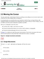
When you have completed the exercise, you will know
the difference between breaking at single points and
breaking an object at two points.
The completed exercise
Completing the Exercise
To complete the exercise, follow the
steps in this book or in the onscreen
exercise. In the onscreen list of
chapters and exercises, click Chapter 5:
Altering Objects. Click Exercise: Break
Objects.
1.
Open C_Break-Object.dwg.
2.
Zoom in on the part of the drawing shown.
3.
To remove a portion of a line:
■ Start the Break command.
■ Select the outside object as shown.
■ Right-click and click First Point.
Note: The benefit of using this option is that
you can select the object and then precisely
select the two break points.
402 ■ Chapter 5: Altering Objects
4.
Select the first break point (1). Then select the
second point (2).
5.
Zoom out to display your entire drawing. Zoom
in to the area shown.
6.
To break the line at a point without removing
any of it:
■ Start the Break at Point command.
■ Select the outer object as shown.
7.
Select point (1) to specify the break point.
8.
Break the line again without removing any of it:
■ Start the Break at Point command.
■ Select the outer object again (1).
■ Select the Intersection at point (2) to
specify the break point.
9.
Select the line between the two break points
to highlight it.
Lesson: Breaking an Object into Two Objects ■ 403
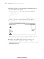
10.
To move this object to the Hidden2 layer:
■ On the Layers panel, click the Layers list.
■ Click the Hidden2 layer to move the
selected object to this layer.
11.
Press ESC. Your drawing should look like the
following image.
12.
Close all files without saving.
404 ■ Chapter 5: Altering Objects
Lesson: Applying a Radius Corner to Two
Lesson: Objects
This lesson describes how to fillet objects using the Fillet command.
Fillets and rounds are common in mechanical drawings, but you can use the Fillet feature across all
design disciplines to create radius geometry connecting two objects.
After completing this lesson, you will be able to identify options of the Fillet command and use the
command to create radius geometry between two objects.
Objectives
After completing this lesson, you will be able to:
■ Use the Fillet command to create radius geometry connecting two objects.
Lesson: Applying a Radius Corner to Two Objects ■ 405
Creating Fillets
You can use the Fillet command to connect two objects quickly with a smoothly fitted arc of a specified
radius. You usually use it to represent a rounded edge on a corner; an inside corner is called a fillet and
an outside corner is called a round. You can fillet lines, arcs, circles, ellipses, polylines, xlines, splines,
and rays.
You can also create a sharp corner with the Fillet command by specifying a radius value of 0.
Original objects
Fillet radius nonzero
Fillet radius zero
Command Access
Fillet
Command Line: FILLET, F
Ribbon: Home tab > Modify panel > Fillet
Menu Bar: Modify > Fillet
Command Options
The following options are available for the Fillet command.
Option
Description
Undo
Reverses the previous action of the Fillet command.
Polyline
Fillets all vertices of a polyline using the current radius value.
406 ■ Chapter 5: Altering Objects
Option
Description
Radius
Sets the radius for the fillet arc.
Trim / No Trim
When Trim mode is selected, the lines are trimmed to be tangent with the fillet. If
Trim mode is set to No Trim, the fillet radius is drawn but the lines are not trimmed.
Multiple
When the Multiple option is selected, you can create multiple fillets without
restarting the command.
Procedure: Applying a Radius Corner with the Fillet Command
The following steps give an overview of how to apply a radius corner with the Fillet command.
1.
Start the Fillet command.
2.
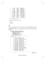
On the command line, verify the current fillet settings. If required, set the options appropriately.
Command: FILLETCurrent settings: Mode = TRIM, Radius = 1.0000Select first object or [Undo/Polyline/
Radius/Trim/Multiple]:
3.
Select the first object to fillet.
4.
Select the second object to fillet.
The fillet is created.
Note: If you choose the Polyline option, the last step is not required, since all vertices of the polyline
are filleted at once.
SHIFT+Select for Zero-Radius Fillet
Regardless of the current Fillet Radius setting, if you SHIFT+select the two objects, a
zero-radius fillet is applied.
Lesson: Applying a Radius Corner to Two Objects ■ 407
Guidelines
■ Depending on the locations you specify, more than one possible fillet can exist between the
selected objects. Always select the part of the objects that you want to keep.
Original objects
Possible results
Possible results
■ You can fillet parallel lines, xlines, and rays. The current fillet radius is ignored and an arc is created
that is tangent to both parallel objects and located in the plane common to both objects.
■ You can also fillet a polygon, or an entire polyline, or remove fillets from an entire polyline.
■ If you set a nonzero fillet radius, fillet arcs are inserted at the vertex of each polyline segment that
is long enough to accommodate the fillet radius.
408 ■ Chapter 5: Altering Objects
Key Points
■ The fillet radius is the radius of the arc that connects the objects.
■ If both objects being filleted are on the same layer, the fillet arc is created on that layer.
Otherwise, the fillet arc is created on the current layer.
■ Entering a radius value of 0 creates a sharp corner.
■ Holding down the shift key while selecting the object to fillet will override the current radius value
and create a radius of 0.
■ An object that is filleted to a polyline becomes part of that polyline.
■ A polyline can not be filleted to an arc. Explode the polyline, then fillet the objects and join them
again using the Polyedit command.
Lesson: Applying a Radius Corner to Two Objects ■ 409
Practice Exercise: Creating Fillets
In this practice exercise, you use the Fillet command
on a simple rectangle.
1.
Draw a rectangle.
2.
To Fillet a single corner:
■ Begin the Fillet command.
■ Enter R and press ENTER.
■ Specify a fillet radius of .25 and press
ENTER.
■ Click the lines near one corner of the
rectangle as indicated below.
3.
Now change the radius and use the Fillet
polyline option:
■ Begin the Fillet command.
■ Enter R and press ENTER.
■ Enter a fillet radius of .5 and press ENTER.
■ Enter P and press ENTER.
■ Select the rectangle.
Note: If this rectangle was made of separate
line segments instead of a polyline, the
previous radius would have remained and you
could not have used the Polyline option to fillet
all of the corners at once.
4.
Now change the fillet radius to 0 to make sharp
corners on the rectangle:
■ Begin the Fillet command.
■ Enter R and press ENTER.
■ Enter a fillet radius of 0 and press ENTER.
■ Enter P and press ENTER.
■ Select the rectangle.
410 ■ Chapter 5: Altering Objects
Exercise: Create a Filleted Corner
In this exercise, you create fillets on the objects
in the drawing. You use different options of the
Fillet command to create the desired results. When
you have finished, you will be able to use the Fillet
command in other drawings.
The completed exercise
Completing the Exercise
To complete the exercise, follow the
steps in this book or in the onscreen
exercise. In the onscreen list of
chapters and exercises, click Chapter 5:
Altering Objects. Click Exercise: Create
a Filleted Corner.
1.
Open M_Create-Fillets.dwg.
2.
Zoom in to the lower-left area of the drawing.
3.
To use the Fillet command to create an end
cap on parallel lines:
■ Start the Fillet command.
■ Right-click anywhere in the drawing area.
Click Multiple.
■ Select the lines as shown.
4.
To complete the fillet:
■ Select the lines on the opposite side of the
view.
■ Press ENTER to end the Fillet command.
5.
Pan or zoom to the top-left of the drawing.
Lesson: Applying a Radius Corner to Two Objects ■ 411
6.
To create a blend between the part profile and
the screw bosses:
■ Start the Fillet command.
■ Right-click anywhere in the drawing area.
Click Multiple.
■ Right-click anywhere in the drawing area.
Click Trim. Click No Trim.
■ Right-click anywhere in the drawing area.
Click Radius.
■ Enter 2. Press ENTER.
■ Select the horizontal line, and then select
the larger circle.
7.
Repeat the selection on the opposite side of
the circle.
The fillet should appear as shown.
8.
To complete the boss creation:
■ Repeat the selection process on the other
bossed areas in the drawing, as indicated
in the following image.
■ Press ENTER to end the Fillet command.
9.
Zoom to display the entire drawing.
10.
To ignore the radius setting and create a sharp
corner while using the fillet command:
■ Start the Fillet command.
■ On the command line, confirm the radius is
still set to 2.0000.
■ Select the horizontal line.
■ Press SHIFT+ select the vertical line to
create a zero-radius fillet.
412 ■ Chapter 5: Altering Objects
11.
To complete the right view:
■ Press ENTER to repeat the Fillet command.
■ On the right-side view, select the top
horizontal line.
■ Press SHIFT+ select the right-side vertical
line to create a zero-radius fillet.
12.
Close all files without saving.
Lesson: Creating an Angled Corner Between Two Objects ■ 413
Lesson: Creating an Angled Corner Between
Lesson: Two Objects
This lesson describes how to use the Chamfer command to create chamfer features on objects in the
drawing.
There are many situations that call for a chamfer. Any time you need to create an angled intersection
on objects in the drawing, the Chamfer command should be your first choice.
After completing this lesson, you will be able to identify options of the Chamfer command and use the
command to create chamfered features.
Objectives
After completing this lesson, you will be able to:
■ Use the Chamfer command to create chamfer features.
414 ■ Chapter 5: Altering Objects
Creating Chamfers
You use the Chamfer command to quickly create a line between two nonparallel lines. It is usually
used to represent a beveled edge on a corner. You can chamfer lines, polylines, xlines, and rays.
Command Access
Chamfer
Command Line: CHAMFER, CHA
Ribbon: Home tab > Modify panel > Chamfer
Note: Select the Chamfer command from the drop-down menu.
Menu Bar: Modify > Chamfer
Lesson: Creating an Angled Corner Between Two Objects ■ 415
Command Options
The following options are available when using the Chamfer command.
Option
Description
Undo
Use this option to undo the previous action of the Chamfer command.
Polyline
Use this option to chamfer a 2D polyline. All polyline vertices are chamfered at the
current distance or angle settings.
Distance
Use this option to specify distance values for the chamfer.
Angle
Use this option to create the chamfers based on one distance and an angle.
Trim
Use this option to set the Trim and No Trim modes. When Trim mode is active, the
objects being chamfered are trimmed to the start of the chamfer lines. When No Trim
mode is set, the objects selected for the chamfer are not trimmed.
Method
Use this option to switch between the Distance or Angle methods for creating the
chamfer.
Multiple
Use this option to create multiple chamfers without having to restart the command.
Using Chamfer Options
■ With the Distance method, you specify the amount that each line should be trimmed or extended.
Original objects
Chamfer distances nonzero
Chamfer distances zero
■ With the Angle method, you can also specify the length of the chamfer and the angle it forms with
the first line.
416 ■ Chapter 5: Altering Objects
■ Using the Trim and No Trim modes, you can trim or extend chamfered objects to the chamfer line
or retain the chamfered objects as they were before the chamfer, as shown next.
■ You can chamfer all corners of a polyline using the Polyline option.
■ The Multiple option allows you to chamfer more than one set of objects without leaving the
command. For example, you could chamfer the four corners of the square shown next with one
Chamfer command.
Procedure: Creating Chamfers
The following steps give an overview of creating chamfers with the Chamfer command.
1.
Start the Chamfer command.
2.
Confirm the settings on the command line. If necessary, adjust the options as required for the design
intent.
Command: _chamfer(NOTRIM mode) Current chamfer Dist1 = 1.0000, Dist2 = 1.5000Select first line or
[Undo/Polyline/Distance/Angle/Trim/mEthod/Multiple]:
3.
Select the first object to be chamfered.
4.
Select the second object to be chamfered.
The chamfer feature is created.
Note: If you choose the Polyline option, step 4 is not required, as all vertices of the polyline will be
filleted at once.
Chamfer Guidelines
■ If both objects being chamfered are on the same layer, the chamfer line is created on that layer.
Otherwise, the chamfer line is created on the current layer.
■ Entering chamfer distances of 0 creates a sharp corner.
■ Setting equal chamfer distances is the same as setting the angle at 45 degrees.
■ When setting chamfer distances the first distance is always applied to the first line you pick.
■ Chamfering a line to a polyline will automatically join it to the polyline.
■ A closed polyline will chamfer in a counter-clockwise direction.
■ Hold down the SHIFT key while selecting the object to override the chamfer distance values and
create a sharp corner.
Lesson: Creating an Angled Corner Between Two Objects ■ 417
Practice Exercise: Creating Chamfers
In this practice exercise, you draw an 8 x 6 rectangle
and create chamfers using the Chamfer command.
1.
To draw the rectangle:
■ Begin the Rectangle command.
■ Click in the drawing window to specify the
first corner.
■ For the other corner, enter @8,6 and press
ENTER.
2.
To make a 45 degree corner using the chamfer
command:
■ Begin the Chamfer command.
■ Right-click anywhere in the drawing. Click
Angle.
■ Enter 1 and press ENTER for the chamfer
length on the first line.
■ Enter 45 and press ENTER to specify the
chamfer angle from the first line.
■ Select the first corner then the adjacent
corner as indicated below.
■ Repeat until all 4 corners are chamfered.
■ Press ENTER to exit the chamfer command.
Note: You could have used the Distance option
and entered both distance lengths at 1 for the
same results.
3.
To chamfer using the polyline option:
■ Draw another 8 x 6 rectangle (see #1).
■ Begin the Chamfer command.
■ See that the current chamfer length is 1
and the angle is 45 degrees.
■ Right-click anywhere in the drawing. Click
Polyline.
■ Select the rectangle.
■ All corners are chamfered.
418 ■ Chapter 5: Altering Objects
4.
To chamfer using the Distance option where
the distances are not equal:
■ Draw another 8 x 4 rectangle.
■ Begin the Chamfer command.
■ Right-click anywhere in the drawing. Click
Distance.
■ Enter 1 for the first chamfer distance and
press ENTER.
■ Enter .5 for the second chamfer distance
and press ENTER.
■ Select the first line (1) and select the
second line (2).
■ Repeat the Chamfer command.
■ Select the line at (3), then select the line at
(4).
Remember that the first distance is always
applied to the first line you select and the
second distance is applied to the second line
selected.
■ Repeat the Chamfer command and add
chamfers to all four corners as shown
below.
5.
To chamfer using the Distance option
combined with the Polyline option when the
distances are not equal:
■ Draw an 8 x 6 rectangle.
■ Begin the Chamfer command.
■ Note that the current chamfer distance 1 is
1 and distance 2 is .5.
■ Right click anywhere in the drawing. Click
Polyline.
■ Select the rectangle.
Chamfer works in a counter-clockwise
direction. Therefore, chamfering a polyline
with non-equal distances gives you this kind of
result.
Lesson: Creating an Angled Corner Between Two Objects ■ 419
Exercise: Create a Chamfered Corner
In this exercise, you create chamfer features using the
Multiple, Distance, and Angle options of the Chamfer
command. When you have completed the exercise,
you will be able to use the Chamfer command to add
chamfer features to geometry in other drawings.
The completed exercise
Completing the Exercise
To complete the exercise, follow the
steps in this book or in the onscreen
exercise. In the onscreen list of
chapters and exercises, click Chapter 5:
Altering Objects. Click Exercise: Create
a Chamfered Corner.
1.
Open M_Create-Chamfers.dwg.
2.
Zoom in on the lower left view of the drawing.
3.
To create a 1-unit chamfer:
■ Start the Chamfer command.
■ Right-click anywhere in the drawing
window. Click Distance.
■ When prompted for the first chamfer
distance, enter 1. Press ENTER.
■ Press ENTER for the second chamfer
distance, as it defaults to the value of the
first chamfer distance.
■ Right-click anywhere in the drawing
window.
■ Click Multiple.
This enables you to create multiple chamfers
without restarting the Chamfer command.
4.
To complete the chamfer:
■ Select the lines indicated in the following
image near their intersections.
Note: The chamfers have already been applied
in this image. You may need to turn on the Trim
option if it is off.
■ DO NOT exit the chamfer command.
Proceed to the next step.
420 ■ Chapter 5: Altering Objects
5.
Select the lines near their intersections as
shown in the following image. Press ENTER to
end the Chamfer command.
6.
Use Zoom and Pan to display the top-left view
in the drawing.
7.
To create more 1-unit chamfers in this view:
■ Start the Chamfer command.
■ Right-click anywhere in the drawing
window. Click Multiple.
■ Select the lines indicated in the following
image.
Note: The lines have already been chamfered
in this image.
8.
Repeat the chamfers on the right side of
the view. Press ENTER to end the Chamfer
command.
9.
To create additional chamfers using the Angle
and Multiple options:
■ Press ENTER to repeat the Chamfer
command.
■ Right-click anywhere in the drawing
window.
■ Click Angle.
■ Enter 1 for the chamfer length on the first
line.
■ Enter 60 for the chamfer angle from the
first line.
■ Right-click anywhere in the drawing
window.
■ Click Multiple.
■ Select the edges in the order indicated in
the following image.
Note: The chamfers have already been applied
in this image.
10.
Select the edges on the opposite side of the
view.
Lesson: Creating an Angled Corner Between Two Objects ■ 421
11.
Use Zoom and Pan to display the lower-left
view as shown.
■ Apply the chamfers to the edges of the part
on both sides of the view.
■ Press ENTER to end the Chamfer command.
12.
Using the Line command, draw line segments
at each location in which a chamfer was
created.
13.
Zoom to display your entire drawing.
14.
Close all files without saving.
422 ■ Chapter 5: Altering Objects
Lesson: Changing Part of an Object's Shape
This lesson describes how to use the Stretch command to change part of an object's shape.
Reusing objects and ease of editing are key benefits of using the Stretch command. As your design
evolves, changes to features naturally occur as part of the process, or perhaps you are attempting to
reuse geometry from another drawing and some features require a change in length or shape. The
Stretch command can help in these situations by enabling you to modify the shape of existing objects
easily.
After completing this lesson, you will be able to describe key aspects of the Stretch command and use
the command to stretch objects.
Objectives
After completing this lesson, you will be able to:
■ Use the Stretch command to stretch objects.
Lesson: Changing Part of an Object's Shape ■ 423
Stretching Objects
You use the Stretch command to change the shape of objects in the drawing, definingthe area to
be stretchedwith a crossing window or crossing polygon selection tool. After you define the stretch
window, you then specify a base point and a second point for the stretch.
Defining the stretch operation with a crossing window or crossing polygon is critical because the area
that is crossed by the selection method determines how the objects are stretched.
Command Access
Stretch
Command Line: STRETCH, S
Ribbon: Home tab > Modify panel > Stretch
Menu Bar: Modify > Stretch
424 ■ Chapter 5: Altering Objects
Procedure: Stretching Objects Using Grips
The following steps give an overview of using grips to stretch objects.
1.
Select an object to activate its grips.
2.
Select any grip (use SHIFT+select to select multiple grips).
3.
Click and drag the grips to a new location.
Procedure: Stretching Objects
The following steps give an overview of stretching objects in a drawing.
1.
Start the Stretch command.
2.
Select the objects to be stretched by defining a crossing window or crossing polygon selection.
3.
Select the base point for the stretch.
Lesson: Changing Part of an Object's Shape ■ 425
4.
Select the second point or enter a value for the stretch distance.
Stretch Guidelines
■ When you stretch objects, you must define the stretch window using a crossing window (CW) or
crossing polygon (CP). If you use implied windowing, you must create the selection from right to
left.
■ Objects that are crossed by the selection window are stretched, while objects that are completely
enclosed by the window are moved.
■ To stretch an object in a straight line, be sure that Polar Tracking or Ortho Mode is on.
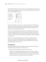
■ After you have selected your object(s) to Stretch, pick a basepoint near the object but far enough
away from any other objects you might snap to accidentally .