Learning AutoCAD 2010, Volume 2 phần 2 pdf
Bạn đang xem bản rút gọn của tài liệu. Xem và tải ngay bản đầy đủ của tài liệu tại đây (9.3 MB, 37 trang )
30 ■ Chapter 6: Working with Layouts
Rotating Viewports
You rotate a viewport with the Rotate command or by using grips. You can also set the entire layout
view to rotate with the viewport by setting the VPROTATEASSOC system variable.
The following image shows a viewport before and after it is rotated.
Before rotation
After rotation
Command Access
VPROTATEASSOC
Command Line: VPROTATEASSOC
VPROTATEASSOC System Variable
The VPROTATEASSOC system variable controls whether the view within a viewport is rotated with the
viewport when the viewport is rotated. The VPROTATEASSOC system variable can be set to one of the
following values.
Option
Description
0
When a viewport is rotated, the view inside is not rotated.
1
When a viewport is rotated, the view inside is rotated to match the rotation of the
viewport.
Lesson: Using Viewports ■ 31
Process: Rotating a View within a Viewport
The following steps give an overview of how to rotate a view within a viewport.
1.
At the Command prompt, enter
VPROTATEASSOC.
2.
Set the value to 1.
3.
On a layout tab, select the desired viewport.
4.
Rotate the viewport to the desired angle.
5.
Observe the entire view rotate within the
viewport.
32 ■ Chapter 6: Working with Layouts
Exercise: Create and Manipulate Viewports
In this exercise, you change the scale factor of a
viewport, move a viewport, freeze a layer in an active
viewport, and create a new viewport.
The completed exercise
Completing the Exercise
To complete the exercise, follow the
steps in this book or in the onscreen
exercise. In the onscreen list of
chapters and exercises, click Chapter 6:
Working with Layouts. Click Exercise:
Create and Manipulate Viewports.
1.
Open M_Create-and-Manipulate-
Viewports.dwg.
2.
In the Layout1 tab, click to select the green
rectangular viewport.
3.
To set the viewport scale:
■ On the status bar, click the Viewport Scale
list and select 1:30.
4.
The floor plan should now appear smaller on
the layout and you should be able to see all of
the dimensions as shown.
5.
Click the Layout2 tab.
Lesson: Using Viewports ■ 33
6.
To move a viewport:
■ Start the Move command.
■ Select the green rectangular viewport that
displays the circular staircase. Press ENTER.
■ Move it to the upper-right corner of the
border, as shown.
7.
To activate model space in the layout:
■ Position the cursor inside the green
rectangular viewport on the left side of the
sheet.
■ Double-click to activate the model space
environment through that viewport.
When the viewport is active, the crosshairs
and UCS icon should appear as shown.
8.
To freeze a layer in the current viewport:
■ Open the Layer Properties Manager.
■ Click the icon in the VP Freeze column for
the layer Internal Wall to freeze that layer
in the current viewport.
■ Click OK.
Notice how the staircase is no longer displayed
in the viewport on the left but it is in the
viewport on the right.
9.
To change the color of a layer in the current
viewport:
■ Open the Layer Properties Manager.
■ Click the icon in the VP Color column for
the layer Furniture.
■ Set the color to magenta.
■ Click OK.
10.
To verify that the Furniture color only changed
in Layout2:
■ Click the Model tab. Confirm that the
furniture color remained brown.
■ Click the Layout1 tab. Notice that the
furniture color remained brown.
■ Click the Layout2 tab. Confirm that the
furniture color is still magenta in this
layout.
11.
To activate the layout environment:
■ Position your cursor in the gray
background outside the paper.
■ Double-click to change the focus back to
the layout environment.
34 ■ Chapter 6: Working with Layouts
12.
To create a viewport:
■ Type -vports on the command line
■ Click and draw a rectangular viewport
in the open area of the paper layout as
shown.
13.
To set the viewport scale:
■ Double-click inside the new viewport to
make it active.
■ On the status bar, click the Viewport Scale
list and click 1:30.
14.
Pan the view in the viewport so you are
viewing the bay walls and couch as shown.
15.
Double-click in the gray area outside the paper.
16.
Grip edit the viewport from the upper-right
corner to crop the display as shown.
17.
The green viewport borders are on the
Viewports layer. To set that layer so it does not
plot:
■ Open the Layer Properties Manager.
■ Click the printer icon in the Viewports layer
row.
With this setting, the viewport borders are not
plotted when you output the drawing.
18.
On the command line, enter VPROTATEASSOC.
Enter 1.
19.
Select the viewport you created and then start
the Rotate command on the command line:
■ Select a corner of the viewport as the base
point for the rotation.
■ For the rotation angle, enter 90 and press
ENTER.
Note that when the rotation is complete, the
view of the drawing rotates with the viewport.
If the VPROTATEASSOC variable is set to zero
the Rotate command only rotates the viewport
and not the view within it.
20.
Close all files without saving.
Challenge Exercise: Architectural ■ 35
Challenge Exercise: Architectural
In this exercise, you use what you learned about working with layouts to configure a layout and a
viewport for your design.
You have the option of completing this exercise using either imperial or metric units.
Select one version of the exercise to complete the steps.
The completed exercise
Completing the Exercise
To complete the exercise, follow the steps in this book or in the onscreen exercise.
In the onscreen list of chapters and exercises, click Chapter 6: Working with Layouts.
Click Challenge Exercise: Architectural Metric.
Metric Units
1.
Open the drawing you saved from the previous challenge exercise, or open M_ARCH-Challenge-
CHP06.dwg.
36 ■ Chapter 6: Working with Layouts
2.
Configure Layout1 to plot with the following settings:
■ Orientation: Landscape
■ Scale:1:1
■ Printer/Plotter: DWF6 ePlot.pc3
■ Paper size: ISO A1 (841 x 594 mm) paper
3.
Rename Layout1 to Plan View.
4.
Add and configure the main viewport on the layout:
■ A view of the main floor plan at a scale of 1:60.
■ Lock the viewport when completed.
5.
Save and close the drawing.
Imperial Units
1.
Open the drawing you saved from the previous challenge exercise, or open I_ARCH-Challenge-
CHP06.dwg.
2.
Configure Layout1 to plot with the following settings:
■ Orientation: Landscape
■ Scale: 1:1
■ Printer/Plotter: DWF6 ePlot.pc3
■ Paper size: ARCH expand D (36.00 x 24.00 Inches)
3.
Rename Layout1 to Plan View.
Challenge Exercise: Architectural ■ 37
4.
Add and configure the main viewport on the layout:
■ A view of the main floor plan at a scale of 3/16" = 1'.
■ Lock the viewport when complete.
5.
Save and close the drawing.
38 ■ Chapter 6: Working with Layouts
Challenge Exercise: Mechanical
In this exercise, you use what you learned about working with layouts to create and configure a layout
with three viewports.
The completed exercise
Completing the Exercise
To complete the exercise, follow the steps in this book or in the onscreen exercise.
In the onscreen list of chapters and exercises, click Chapter 6: Working with Layouts.
Click Challenge Exercise: Mechanical.
1.
Open the drawing you saved from the previous challenge exercise, or open M_MECH-Challenge-
CHP06.dwg.
Challenge Exercise: Mechanical ■ 39
2.
Create a new layout configuration with the following settings:
■ DWF6 ePlot.pc3
■ ISO A3 (420 x 297)
■ Three viewports that do not show on the plot
■ A scale factor for the view at the top of 1:1
■ A scale factor for the view on the left of 1:2
■ A scale factor for the view of the assembly on the right of 1:4
3.
Perform a cleanup:
■ Rename the layout Parts.
■ Delete Layout2.
■ Return to model space.
4.
Save and close the drawing.
40 ■ Chapter 6: Working with Layouts
Chapter Summary
There are several ways you can prepare your design data for outputting to paper or to an electronic
file. Layouts are an environment in which you select the paper size for printing on and then add
borders, title blocks, and any textual notes for annotating the drawing. You display model space
geometry on the paper in the layout by creating viewports, which can display various permutations
of the data at different scales to help you to focus on what you are trying to communicate about your
design.
Having completed this chapter, you can:
■ Identify the environments in which you can plot data and create a new layout.
■ Create and manipulate viewports.
■ In this exercise, you use what you learned about working with layouts to create and configure a
layout with three viewports.
Chapter Overview ■ 41
Chapter
7
Annotating the Drawing
No drawing is complete without some kind of text to annotate the design. In this chapter, you learn to
create and edit text objects. You also learn how to edit and scale text so that it appears consistently in
your drawing and drawing layouts.
Objectives
After completing this chapter, you will be able to:
■ Use the Mtext command to create multiline text.
■ Create single line text.
■ Use different methods to edit text.
■ Create text styles to manage text.
Standard Object Snap and Status Bar Settings
Before completing the exercises in this chapter, refer to the "Settings for the
Exercises" section in the Introduction in Volume 1.
42 ■ Chapter 7: Annotating the Drawing
Lesson: Creating Multiline Text
This lesson describes how to create Multiline Text.
It is common practice to place paragraph style notes on drawings. These notes generally refer to the
drawing as a whole rather than specific features, and often require more formatting options than
standard single-line text objects.
The following illustration shows multiline a multiline text object being created.
Objectives
After completing this lesson, you will be able to:
■ Describe Multiline text.
■ Use the Multiline Text command to create and format paragraphs of text.
■ List the changes implemented to increase productivity when using Mtext.
Lesson: Creating Multiline Text ■ 43
About Multiline Text
You use the Multiline Text command to create paragraphs of text for notes and other information in
your drawing or drawing Layout.
Words and paragraphs remain intact and the width can be adjusted using grips.
Multiline Text Defined
Multiline Text is an assembly of words, symbols, and other textual information that can be written,
formatted, and edited using the AutoCAD® built-in editor. You can create several paragraphs of text as
a single multiline (mtext) object and format the text appearance which includes justification, italics,
underline, bold, and inserting symbols.
44 ■ Chapter 7: Annotating the Drawing
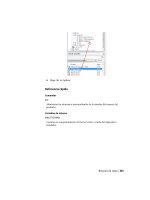
The illustration below shows the editing options that are available within the multiline Text Editor
when you right-click. These options also appear in the ribbon when the Multiline Text command is
invoked or the text is selected for editing.
The options for the Text Editor appear within the AutoCAD drawing environment and are similar to
other word programs.
Example of Multiline Text
This is an example of Multiline Text.
Lesson: Creating Multiline Text ■ 45
Example of Single Line Text
The text in single line text, which you will learn about in the next section, does not allow paragraph
formatting.
Creating Multiline Text
You use the Multiline Text command to create paragraph style text. You can create text in your drawing
using formatting options found in most standard word processors, as well as functions that are specific
to the software.
With the Multiline Text editor, you can:
■ Create paragraph styled text.
■ Create numbered and bulleted lists.
■ Insert specific drafting and engineering symbols.
■ Change the text justification.
■ Create columns of text.
■ Create Fields such as date, time and author.
Once the Multiline Text area is specified, the ribbon displays the Text Editor tool panels.
46 ■ Chapter 7: Annotating the Drawing
Command Access
Multiline Text
Command Line: MTEXT, MT, T
Ribbon: Annotate tab > Text panel > Multiline Text
Ribbon: Home tab > Annotation panel > Multiline Text
Menu Bar: Draw > Text > Multiline Text
Multiline Text Tab
When you use the Multiline Text command, the ribbon opens to the Multiline Text tab displaying the
Text Editor. Use the options on the panels to control the text appearance, format your paragraphs,
insert symbols, add fields, check spelling, and perform other functions specific to the annotation of
your drawing.
Style controls text style and text height.
Formatting controls whether the text is bold, italic, underlined, or overlined. You can also choose to
override the current text style font and color.
Paragraph controls the justification, line spacing, numbering, and bullets of selected text.
Insert allows you to insert symbols, columns, and fields (such as author and date).
Lesson: Creating Multiline Text ■ 47
Spell Check allows you to check spelling.
Tools contains the find and replace, import text, and change case options.
Options controls the display of text box rulers and changes the character set and editor settings.
Close enables you to close the Multiline Text Editor.
Editing Multiline Text
To edit existing multiline text, double-click the text. The Text Formatting toolbar
appears so you can edit the text in the same way you created it.
Procedure: Creating Multiline Text
The following steps give an overview of creating multiline text.
1.
Start the Multiline Text command.
2.
Click two points to define the text area.
3.
Confirm the text style (1) and text height (2) settings on the Style panel.
48 ■ Chapter 7: Annotating the Drawing
4.
Begin creating text using the options as required for numbered or bulleted lists and symbols.
5.
Use the ruler to adjust the width and height of the text area if necessary.
Lesson: Creating Multiline Text ■ 49
6.
Double-click outside the Text Editor to accept the text and exit.
Multiline Text Guidelines
■ Keep the text window size relative to the area where you want the text to appear in the drawing.
Use the grips to adjust the width and height.
■ You can override the font in the current style by setting specific font options on the Formatting
panel.
■ To ensure that multiline text sentences maintain the ability to wrap within the text box, press
ENTER only to begin a new line or paragraph.
■ To format selected text, select the text first, then select the Formatting option. Single-clicking
places the cursor in a new location, double-clicking selects the entire word and triple-clicking
selects the entire paragraph.
■ You can copy text from another location or program and paste it into the Text Editor. However it
may retain the text format associated with its source. Paste the text first into Notepad then copy
it again and past it into the Multiline Text Editor. This way it retains the text style you designate in
AutoCAD.
■ Multiline Text options may also be accessed by right-clicking in the Text Editor window.
■ If you Explode multiline text, it becomes single lines of text.
■ You can type MTEXT or simply T and press ENTER to begin the Multiline Text command.
■ It is good practice to always place text on its own layer.
50 ■ Chapter 7: Annotating the Drawing
MText Columns and Grips
When you use Mtext objects in your drawings, you have the ability to format the text into columns.
You can also edit the text using grips in a similar manner to tables.
Placing Mtext
When you place Mtext, the Text Editor tab activates on the ribbon. Additionally, you can specify that
you want the text to be formatted with columns using the Column option on the Insert panel.
Column options on the ribbon
Column Settings dialog box
The following column types are available.
Option
Description
Dynamic Column
Sets the dynamic columns mode to the current Mtext object. Dynamic columns are
text driven. Adjusting the columns affects the text flow and the text flow causes
columns to be added or removed. Automatic or manual height options are available.
Static Column
Sets the static columns mode to the current Mtext object. You can specify the total
width and height of the Mtext object and the number of columns. All of the columns
share the same height and are aligned at both sides.
No Column
Specifies no columns for the current Mtext object.
You can also insert a manual column break from the ribbon. This option is disabled
when No Columns is selected.
Lesson: Creating Multiline Text ■ 51
Editing Mtext with Grips
Grip editing mtext is the ability to adjust column width and height using grips.
Location Grip
Mtext Width and Mtext Height
Column Width
Mtext Height
Mtext Width
52 ■ Chapter 7: Annotating the Drawing
Exercise: Create Multiline Text
In this exercise, you use the Multiline Text command
to create multiline text in the drawing.
The completed exercise
Completing the Exercise
To complete the exercise, follow the
steps in this book or in the onscreen
exercise. In the onscreen list of
chapters and exercises, click Chapter 7:
Annotating the Drawing. Click Exercise:
Create Multiline Text.
1.
Open C_Create-Mtext.dwg.
2.
Zoom into the upper-right corner of the title
block.
3.
On the status bar, click Object Snap to turn it
off.
4.
To place an address on the title block:
■ Start the Multiline Text command.
■ Click two points to define the multiline text
box as shown.
5.
To set the text height and enter the address:
■ On the Style panel, in the text size list,
enter 6.
■ Enter the text as shown.
■ Press ENTER after the last line.
6.
To change the text height and enter the phone
and fax numbers:
■ In the Text Height list, enter 3.
■ Press ENTER.
Note: You can enter values or select values in
this list.
■ Enter the text for the telephone and fax
numbers as shown.
■ Click on the Close Text Editor on the Close
panel or double-click outside the Text
Editor.
Lesson: Creating Multiline Text ■ 53
7.
Zoom to the extents of the drawing.
8.
Zoom a window around the view label text.
9.
Repeat the Multiline Text command. Click
two points to define the multiline text box as
shown.
10.
On the Style panel, select ViewLabel from the
text style list.
11.
Enter the text as shown below.
12.
Double-click outside the Text Editor to close it.
13.
Zoom to the extents of the drawing.
14.
Close all files without saving.
Edit Mtext to Display Columns
In this exercise, you adjust existing text from a single
column to a more orderly column layout.
1.
Open I_Mtext-Columns and Grips.dwg .
2.
Change to the Title Block layout.
54 ■ Chapter 7: Annotating the Drawing
3.
Select the Mtext object.
4.
Open the Properties palette from the
command line. Under Text, for Columns, click
[ ].
5.
In the Column Settings dialog box:
■ Under Column Type, select Dynamic
Columns.
■ For Height, enter 6".
■ Under Width, for Column, enter 6".
■ For Gutter, enter 7/16".
■ Click OK.
The Mtext object is displayed with four
columns.
6.
On the Mtext object, click the Mtext Height
grip.