Microsoft Press mcts training kit 70 - 648 server virtualization phần 3 ppsx
Bạn đang xem bản rút gọn của tài liệu. Xem và tải ngay bản đầy đủ của tài liệu tại đây (1.41 MB, 65 trang )
108 CHAPTER 2 Configuring Hyper-V Hosts
FIGURE 2-26 The Create Virtual Networks page of the Hyper-V role Installation Wizard
After the virtual switch is created, the network adapter begins to act like a normal switch,
except that the switch is software-based and ports are added and removed dynamically
as needed.
This process is not duplicated when you work with Hyper-V on Server Core. Because you
use a command line to add the Hyper-V role, you do not get to create a virtual network
switch. Instead, the virtual network switch must be created manually after the role installation
and its corresponding reboot.
External connections will automatically be linked to the virtual network switch. In this case, all
network traffic is routed through the virtual switch as if it were a physical switch (see Figure 2-27).
Because the external connection is linked to a port on the virtual switch, applications within the
VM that must connect externally will have all traffic routed through the virtual network adapter
to the port on the virtual switch, then through the physical network adapter and out to the
external world.
Lesson 3: Configuring Virtual Networking CHAPTER 2 109
Networking
Application
Virtual
NIC
Virtual
Switch
VMOne
Networking
Application
Virtual
NIC
VMTwo
Networking
Application
Physical Server
Virtual NIC binding: All
except Microsoft virtual
network switch protocol
Physical NIC binding:
Microsoft virtual network
switch protocol
Physical
Switch
FIGURE 2-27 The operation of an external network in Hyper-V
Internal connections are not linked to the virtual network switch. Because of this, they can
only communicate with the host and with other virtual machines bound to the same network
(see Figure 2-28).
Private networks are not linked to the virtual network switch either. They only provide
access to other virtual machines linked to the same network (see Figure 2-29).
Hyper-V can emulate two different types of network adapters: the network adapter
and the legacy network adapter. For virtual machines to be able to work with the network
adapter, they must be able to install and run the Hyper-V Integration Services. If the
operating system in a VM does not support Integration Services, it must use the legacy
network adapter, which emulates an Intel 21140–based PCI Fast Ethernet Adapter. Note
that the legacy network adapter is also required if a virtual machine needs to boot from a
network, such as when you use the Preboot Execution Environment (PXE) to boot a machine
from the network to install an operating system into it. In this example, there is no operating
system yet on the VM and thus no Integration Services are installed. This is why only the
legacy network adapter works in this case.
110 CHAPTER 2 Configuring Hyper-V Hosts
Virtual
Switch
Networking
Application
Virtual NIC binding: All
except Microsoft virtual
network switch protocol
Networking
Application
Virtual
NIC
VMOne
Networking
Application
Virtual
NIC
VMTwo
FIGURE 2-28 The operation of an internal network in Hyper-V
Virtual
Switch
Networking
Application
Virtual
NIC
VMOne
Networking
Application
Virtual
NIC
VMTwo
FIGURE 2-29 The operation of a private network in Hyper-V
exaM tIp LEGACY NETWORK ADAPTERS
Make sure to remember that you must use the legacy network adapter to have a machine
boot from the network—this is definitely on the exam.
When VMs need to communicate to the parent partition, they can do so in one of two ways.
First, the VM can be linked to an external virtual network adapter that then routes the traffic to
the port on the virtual switch and out to the physical adapter. The traffic then returns through
a second physical adapter to communicate with the Hyper-V system. Second, the VM can
be routed directly through the virtual network adapter to the parent partition. Although this
Lesson 3: Configuring Virtual Networking CHAPTER 2 111
second method is more efficient because the traffic does not have to loop back into the
system, this won’t occur until the virtual network uses its built-in algorithm to determine the
most efficient port to direct traffic to and then send the traffic to that port. Traffic is sent to all
ports by default until the algorithm kicks in and determines the best possible route.
Using the Virtual Network Manager Tool
You rely on the Virtual Network Manager tool within Hyper-V Manager to create and modify
virtual networks. As a best practice, you should create at least one of each of the three virtual
network adapter types and name them appropriately. This will facilitate your choices when
you create or configure virtual machines and you need to attach them to a given network.
As mentioned in the previous section, when you install the Hyper-V role on a full
installation and you select to create a virtual network during the installation process, Hyper-V
automatically turns the selected physical adapter into a virtual network switch and creates
the first external virtual network adapter. However, Hyper-V does not rename either adapter,
which can lead to some confusion when working with network adapters on Hyper-V hosts.
Creating virtual network adapters is relatively simple. You use the Virtual Network Manager
link in the Actions pane to launch the tool (see Figure 2-30). This tool lets you create any of the
three network adapter types as well as rename and modify existing virtual network adapters.
If you are using the full installation of Windows Server 2008, the first thing you should do
is rename the external virtual network adapter that was automatically created during the
installation of the Hyper-V role to a more significant name such as Hyper-V External.
FIGURE 2-30 Using the Virtual Network Manager
112 CHAPTER 2 Configuring Hyper-V Hosts
You can then proceed to create additional networks. Create at least one of each of the
three network adapter types. To do so, you need to click New Virtual Network to the left
of the dialog box, choose the type of network you want to create, and then click Add. This
creates the network adapter. Name it and provide a description for the adapter. Click Apply
to set your changes. Repeat the process for each adapter type.
Note that you can assign a virtual local area network (VLAN) number to both the external
and internal network adapter types. This assignment can be done at any time, either during
the creation of a network adapter or through reconfiguration once it has been created. This
is done through the Enable Virtual LAN Identification For The Parent Partition option and is
used to specify an identification number to isolate network traffic from the operating system
that runs in the parent partition (see Figure 2-31).
FIGURE 2-31 Assigning a VLAN to the parent partition
You can use virtual LAN identification as a way to isolate network traffic. However, this
type of configuration must be supported by the physical network adapter. VLAN tagging
isolates all parent partition traffic using this network adapter. This does not affect the
operation of a virtual machine in any way, but it segregates parent partition traffic from virtual
machine traffic. You can also assign VLANs to virtual machines through the virtual machine
configuration (see Figure 2-32). In this case, the traffic initiated by the virtual machine going
through this network adapter will be limited to the virtual LAN ID number you assign.
FIGURE 2-32 Assigning a VLAN to a network adapter in a VM
More Info PARENT PARTITION VLAN TAGGING
For more information about configuring virtual LAN identification for the parent partition,
see the Hyper-V deployment content at />Note that when you create virtual network adapters, corresponding adapters are created
in the network connections of the parent partition. This occurs for both the external and
internal network adapter but not for the private network adapter because the private adapter
is not bound to the physical adapter in any way.
Lesson 3: Configuring Virtual Networking CHAPTER 2 113
You should rename the connections created in Network Connections so that you can
more easily identify which connection is which (see Figure 2-33). Do this using the Rename
command in the shortcut menu for each adapter.
FIGURE 2-33 Renaming adapters to better identify them
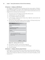
Practice Working with Virtual Networks
In this practice, you will configure virtual networking on your two host servers, ServerFull01
and ServerCore01. This practice consists of two exercises. The first focuses on creating
additional virtual network adapters on the full installation of Windows Server 2008. In the
second, you create a virtual network switch on Server Core and then you create virtual
network interface cards on Server Core. When this practice is complete, your host servers will
be configured to support all types of networking in Hyper-V.
exercise 1 Create Virtual Network Interface Cards on a Full Installation
In this exercise you will configure additional network adapters on the full installation of Windows
Server 2008. This exercise is performed on ServerFull01. Log in with domain administrator
credentials.
1. This operation is performed either with Hyper-V Manager or with the Hyper-V Manager
section of Server Manager. Click ServerFull01 in the tree pane under Hyper-V Manager.
2. Click Virtual Network Manager in the Actions pane of the console. This opens the
Hyper-V Virtual Network Manager dialog box. Note the existing network. This network
was created when you installed the Hyper-V role.
3. Rename the existing connection. Click the connection in the left pane of the dialog
box, select the name in the right pane, and rename it Hyper-V External. Click Apply.
Note that this network is of an external type and is bound to one of your physical
network interfaces.
114 CHAPTER 2 Configuring Hyper-V Hosts
4. Now create a second virtual adapter. Click New Virtual Network in the left part of the
dialog box, choose Internal, and then click Add.
5. Name the adapter Hyper-V Internal and make sure Internal Only is selected as the
connection type. Note that as with the External connection type, you can assign a
VLAN to the parent partition. You do not need to do so at this time. Click Apply.
6. Now create a third virtual adapter. Click New Virtual Network in the left part of the
dialog box, choose Internal, and then click Add.
7. Name the adapter Hyper-V Private and make sure Private Virtual Machine Network
is selected as the connection type. Note that this network type does not allow you to
assign a VLAN to the parent partition because there is no link to the parent partition in
this network connection type. Click OK. Your three network types have been created.
8. Move to the Network Connections window to rename the connections. Renaming the
connections makes it much easier to link the network with the network type when
working in the Windows interface of the parent partition. Click Start and then Control
Panel. In Control Panel, click Network And Internet, then click Network And Sharing
Center, and then click Manage Network Connections in the Tasks section of the
window. This opens the Network Connections window.
9. Rename each connection. You can check each connection’s properties to make sure
you are renaming the appropriate network. Begin with the new virtual switch, which
actually is your physical network adapter. Right-click it and choose Rename. Type
Physical NIC and press Enter. The properties of this NIC should only list the Microsoft
Virtual Network Switch as enabled.
10. Repeat the process with each adapter in the window. Rename the external adapter
to Hyper-V External and the internal adapter to Hyper-V Internal. Your Hyper-V
network configuration is complete.
exercise 2 Create a Virtual Switch on a Server Core installation
In this exercise you will create a virtual network switch on Server Core. Note that the Server
Core Hyper-V role installation does not create this virtual switch the way the full installation
does. You must create this switch interactively. Perform this operation from ServerFull01. Log
on with domain administrator credentials.
1. This operation is performed either with Hyper-V Manager or with the Hyper-V
Manager section of Server Manager. Click ServerCore01 in the tree pane under
Hyper-V Manager.
2. Click Virtual Network Manager in the Actions pane of the console. This opens the
Hyper-V Virtual Network Manager dialog box. Note the there is no existing network
adapter in this interface.
3. The New Virtual Network and the External Network type should already be selected.
Click Add.
4. Name this adapter Hyper-V External, make sure the External connection type is
selected, and make sure the appropriate adapter is selected in the drop-down list.
Lesson 3: Configuring Virtual Networking CHAPTER 2 115
This adapter should not be the one you are using to remotely connect to Server
Core. Do not apply a VLAN to the parent partition at this time. Click Apply. The Apply
Networking Changes warning will appear (see Figure 2-34). Click Yes. You shouldn’t
have issues with this change as long as you selected the appropriate adapter in the
drop-down list. If you don’t, you will lose connectivity with the Server Core computer.
FIGURE 2-34 The Hyper-V Networking Changes warning
5. Create a second virtual adapter. Click New Virtual Network in the left part of the dialog
box, choose Internal, and then click Add.
6. Name the adapter Hyper-V Internal and make sure Internal Only is selected as the
connection type. Note that as with the External connection type, you can assign a
VLAN to the parent partition. You do not need to do so at this time. Click Apply.
7. Create a third virtual adapter. Click New Virtual Network in the left part of the dialog
box, choose Internal, and then click Add.
8. Name the adapter Hyper-V Private and make sure Private Virtual Machine Network
is selected as the connection type. Note that this network type does not allow you to
assign a VLAN to the parent partition because there is no link to the parent partition in
this network connection type. Click OK. Your three network types have been created.
9. You can also rename the network adapters in Server Core to make them easier to
manage. To do so, you need to log on to the Server Core machine and use the netsh
command to rename each connection. Log on with domain administrator credentials.
10. Begin by listing the adapters, making note of the adapter ID number and then rename
each adapter. Use the following commands. In this case, the old connection names
were Local Area Connection 3 and Local Area Connection 4. Your connection names
may differ from these. This is why you run the show interface command first.
netsh interface ipv4 show interface
netsh interface set interface name="Local Area Connection 3" newname
="Hyper-V External"
netsh interface set interface name="Local Area Connection 4" newname
="Hyper-V Internal"
116 CHAPTER 2 Configuring Hyper-V Hosts
If you run the show interface command again (hint: use the up arrow to call the
command back), you will see that the interfaces have been renamed. Networking is
ready on this server.
Quick Check
1. How many virtual networks cards can each enlightened VM access?
2. What is the difference between an external connection and an internal connection?
Quick Check Answers
1. Each enlightened VM can access up to 12 virtual network cards—8 virtual
network adapters and 4 legacy virtual network adapters.
2. The external adapter is a connection to a physical network adapter. Machines
using this adapter can access a physical network, other virtual machines on this
network, the host server, and all other external virtual or physical machines
connected to this network. The internal adapter is a connection that only
supports communications between the host server and the VM and other virtual
machines on the same network.
Suggested Practices CHAPTER 2 117
Case Scenario: Networking Virtual Machines
In the following case scenario, you will apply what you have learned about preparing your
Hyper-V host servers. You can find answers to these questions in the “Answers” section on the
companion CD which accompanies this book.
You are the resource pool administrator for the Graphics Design Institute and you have
been asked to prepare the network connections required to host virtual machines on a
Hyper-V server. Table 2-3 outlines the VMs you will require and the type of networking traffic
each will generate. Your job is to propose which type of virtual network adapter should be
used for each VM.
TABLE 2-3 Virtual Machine List
VIRTUAL MACHINE NETWORK TRAFFIC TYPE
DC01 AD DS for a production forest.
DC02 AD DS for a production forest.
Web01 Web server running Internet Information Services for a public
Web site.
File01 Internal production file server.
DCTest01 AD DS for a test forest. This forest should not have any connection
to the production forest.
WebTest01 Staging Web server for the production Web site.
1. Based on the information in Table 2-3, which connection type would you use for the
production machines?
2. Which connection type should you use for the test machines?
3. The Web production team wants to be able to upload content into the test Web server,
and once it passes approval, they want to automatically upload it from the test server
to the production server. Which type of connections should each server contain to
make this scenario work?
Suggested Practices
To help you successfully master the exam objectives presented in this chapter, complete the
following tasks.
Windows Server 2008 Configuration
n
Practice 1 Take the time to become thoroughly familiar with the configuration of
the full installation. It will be useful for the exam, and also for the configuration of your
own servers.
118 CHAPTER 2 Configuring Hyper-V Hosts
n
Practice 2 Take the time to become thoroughly familiar with the configuration of
Server Core installations. It will be useful for the exam and also for the configuration of
your own servers.
Hyper-V Role Installation
n
Practice 1 Take the time to become familiar with the process used to enable
Hyper-V. There are several intricacies in this process and a few differences between the
process you use on the full installation and the Server Core installation.
Virtual Network Configuration
n
Practice 1 Practice installing virtual adapters of each type. Learn the configuration
parameters for each. Also take the time to view the settings in each adapter.
n
Practice 2 Practice installing virtual adapters of each type on Server Core. Use the
command line to view adapter settings and gain a better understanding of virtual
networking on this installation type.
Chapter Summary
n
Each server that is deployed should be configured before use. The full installation
includes a window called Initial Configuration Tasks (ICT) that provides a single
interface to perform several of these configuration activities. Server Core does not
have a graphical interface but it is important to perform similar configuration tasks.
The entire process in Server Core is performed through the command line.
n
The Hyper-V role installation is similar on the full installation and the Server Core
installation. You need to download and install the Hyper-V RTM update and install
other required updates such as the language pack update or additional updates based
on which kind of system you use to manage Hyper-V.
n
The machines on which you install Hyper-V must include hardware-assisted virtualization
and Data Execution Prevention. They must be accessible from the BIOS system. Both
must be enabled for Hyper-V to operate.
n
Hyper-V relies on two consoles to manage hosts and virtual machines. The Server
Manager console provides a single interface for all server operations. This console
includes a server summary, a roles summary, a features summary, and access to
additional resources and support. It also includes a Hyper-V Manager section once the
role is installed. In addition, you can use the stand-alone Hyper-V Manager console. This
console includes controls for virtual machines, VM snapshots, and Hyper-V server. This
console can run on Windows Server 2008 or on Windows Vista with Service Pack 1.
n
By default, the storage location for virtual machine configuration files and virtual hard
drive is not in the same container. The first location is in the public user profile and
the second location is in the ProgramData folder. It is good practice to keep all virtual
machine files together to simplify VM management.
Chapter Summary CHAPTER 2 119
n
In Hyper-V, virtual machines connect to a network using network adapters or legacy
network adapters. Enlightened VMs can use both types but legacy machines need to
use device emulation. There are several types of networking connections: external,
internal, private, and dedicated.
n
You use the Virtual Network Manager tool in Hyper-V Manager to manage virtual
network cards.
n
Don’t forget that Hyper-V cannot use wireless network adapters because the parent
partition cannot bind them to the virtual switch.
n
In Server Core, you use a command line to add the Hyper-V role and because of
this, the virtual network switch is not created during this process. You must create it
manually later.
CHAPTER 3 121
C H A P T E R 3
Completing Resource Pool
Configurations
Y
our host server infrastructure is almost ready to manage and maintain virtual
machines. Only a few elements need to be finalized before this can happen. So far,
you have installed and implemented the Hyper-V role on both the full and the Server
Core installations of Windows Server 2008. You discovered that Hyper-V required
special hardware or x64 hardware that also included processors with hardware-assisted
virtualization. You also discovered how Hyper-V’s parent and child partitions interact with
each other to support virtual machine operation. You learned that Hyper-V manages both
enlightened and legacy guest operating systems in virtual machines.
However, one of the most important aspects of a Hyper-V deployment and the
transformation of production computers into virtual machines is fault tolerance. When a
Hyper-V host runs 10 or more production virtual machines, you simply cannot afford any
downtime from the host server. This is why you must cluster your host servers, ensuring that
the workloads of each node in the cluster are protected by other nodes in the cluster. If one
host fails, all of the virtual workloads on that host are automatically transferred to other
nodes in the cluster to ensure service continuity. It’s bad enough when you have one server
failure. You cannot afford to have multiple virtual workloads failing at the same time because
the host server they were running on was not configured to be fault tolerant. Fault tolerance
for Hyper-V hosts is provided by the Windows Server 2008 Failover Clustering feature.
In addition, you must ensure that you can manage your host servers from remote
systems, especially if you have configured your Hyper-V hosts to run the Server Core
installation of Windows Server 2008. Remote management tools include the Hyper-V
Manager, which is available as part of the Remote Server Administration Tools (RSAT) for
Window Server. Hyper-V Manager is sufficient to manage a small number of host servers.
However, when you begin to create massive farms of host servers all clustered together,
you begin to see the failings of Hyper-V Manager and need a more comprehensive tool,
one that will let you manage host server farms as a whole. For Hyper-V, this tool is System
Center Virtual Machine Manager 2008 (SCVMM). Part of the System Center family of
Microsoft management tools, Virtual Machine Manager can manage both Hyper-V and
Virtual Server. It also supports the migration of physical computers to virtual machines or
virtual machines in another format to Hyper-V VMs. Finally, it lets you manage multiple
hypervisors in the event that you have already proceeded with server virtualization and you
are running tools such as VMware ESX Server as well as Hyper-V.
C o n t e n t s
CHAPTER 3 121
Completing Resource Pool Configurations 121
Before You Begin . . . . . . . . . . . . . . . . . . . . . . . . . . . . . . . . . . . . . . . . . . . . . . . .122
Lesson 1: Configuring Hyper-V High Availability . . . . . . . . . . . . . . . . . . . .123
Understanding Failover Clustering 123
Creating a Hyper-V Two-Node Cluster 132
Lesson 2: Working with Hyper-V Host
Remote Administration . . . . . . . . . . . . . . . . . . . . . . . . . . . . . . . . . . . . . . .148
Deploying Hyper-V Manager 148
Deploying the Failover Cluster Management Console 152
Understanding System Center Virtual Machine Manager 154
Preparing for SCVMM Implementation 168
Lesson 3: Optimizing Hyper-V Hosts . . . . . . . . . . . . . . . . . . . . . . . . . . . . . . .186
Managing Windows Server 2008 System Resources 186
Optimizing Hyper-V Operations 199
Case Scenario: Deploying SCVMM on Physical
or Virtual Platforms . . . . . . . . . . . . . . . . . . . . . . . . . . . . . . . . . . . . . . . . . . .206
Suggested Practices . . . . . . . . . . . . . . . . . . . . . . . . . . . . . . . . . . . . . . . . . . . . .206
Failover Clustering 206
SCVMM Installation 207
Performance Monitoring 207
Chapter Summary . . . . . . . . . . . . . . . . . . . . . . . . . . . . . . . . . . . . . . . . . . . . . . .207
122 CHAPTER 3 Completing Resource Pool Configurations
Before you move on to populating your host server farm, you need to ensure that your
Hyper-V hosts are running at their optimum peak. This ensures that your systems provide the
very best platform to host the VMs you use in production. Then and only then can you move
your production systems into VMs and transform your data center.
Exam objectives in this chapter:
n
Configure Hyper-V to be highly available.
n
Configure remote administration.
n
Manage and optimize the Hyper-V Server.
Before You Begin
To complete this chapter, you must have:
n
Access to a setup as described in the Introduction. At least two machines are required:
one running a full installation of Windows Server 2008 and the other running Server
Core. These machines were prepared in the practices outlined in Lesson 3 of Chapter 1,
“Implementing Microsoft Hyper-V” and then configured with the Hyper-V role in
Chapter 2 “Configuring Hyper-V Hosts.”
n
In this chapter, you will continue the build process for these machines and transform
them into a Failover Cluster. You will also create a System Center Virtual Machine
Manager machine to manage this cluster.
Lesson 1: Configuring Hyper-V High Availability CHAPTER 3 123
Lesson 1: Configuring Hyper-V High Availability
High availability is an absolute must for any host server environment because each host
server runs several virtual machines. No one can afford the potential loss of productivity that
would be caused if all of the production VMs on a host server were to fail because the host
server failed. This is why this lesson forms a key element of any resource pool infrastructure.
After this lesson, you will be able to:
n
Understand Failover Clustering principles in general.
n
Understand Failover Clustering requirements.
n
Create a two-node Hyper-V cluster.
n
Manage Hyper-V host clusters.
Estimated lesson time: 60 minutes
Understanding Failover Clustering
Microsoft has enhanced the Failover Clustering feature in Windows Server 2008 to better
support the concept of host servers. Prior to the release of Windows Server 2008 with
Hyper-V, failover clusters were primarily used to protect critical workloads such as Microsoft
Exchange e-mail systems, SQL Server database systems, file and print systems, and other
workloads that organizations felt required an “always-on” capability. Note, however, that not
all Windows workloads are suited to failover clustering. Windows Server 2008 also includes
the ability to support fault tolerance through the Network Load Balancing (NLB) feature.
NLB creates a redundant service by using a central Internet Protocol (IP) address for a given
service. The NLB service then redirects the traffic it receives on this central address to servers that
are part of the NLB farm. When a server fails, the NLB service automatically takes it out of the farm
temporarily and redirects all traffic to the other available farm members. Because NLB is a traffic
director, all of the computers in an NLB farm must include identical content to provide an identical
experience to the end user. This is one reason why front-end Web servers are ideally suited to
NLB farms. Web servers often include read-only content that users can browse through. Whether
the user is on one server or another does not matter because all of the content is identical.
Because of the nature of the NLB service, the services that are best suited to participate in an NLB
farm are called stateless services—the user does not modify information in a stateless farm and
only views it in read-only mode. NLB clusters can include up to 32 nodes (see Figure 3-1).
Failover clusters are different from NLB clusters in that they include stateful services—
services that support the modification of the information they manage. Database stores,
mailbox stores, file stores, and printer stores are all examples of services that manage stateful
information—information that is often modified each time a user accesses it. Because of this,
the failover cluster does not include machines with identical content. Although each machine
includes identical services, the information store they link to will be unique. In addition, because
the information store is unique, only one server hosts a particular service at one point in time.
This is different from the NLB cluster where each machine provides the same service.
124 CHAPTER 3 Completing Resource Pool Configurations
End Users
Unique NLB IP address
NLB Redirector
NLB
Node 1
NLB
Node 2
NLB
Node 3
NLB
Node 4
NLB
Node 32
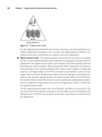
FIGURE 3-1 Stateless NLB clusters can include up to 32 nodes.
Windows Server Failover Clustering supports two types of configurations: the single-site
cluster and the multi-site cluster. In a single-site cluster, cluster nodes are linked to a single shared
storage matrix (see Figure 3-2). This shared storage container is divided up into several contain-
ers, or logical units (LUNs), each of which is tied to a particular service. Each of the nodes in the
cluster that provide fault tolerance for a service has linked paths to the LUN that contains the
data for the service. For example, if you are running a two-node Exchange Mailbox server cluster,
each node will have a linked path to the LUN containing the mailboxes, but only one of the nodes
will have an active connection to the LUN at one time. If a failure occurs on this node, the service
is automatically failed over to the second node. At that time, the second node’s link to the LUN is
activated as it takes over the service. This is the shared-nothing clustering model—only one node
can modify data in the data store of a given service at one time.
Update alert HYPER-V SHARED-EVERYTHING CLUSTERS
Microsoft has modified the shared-nothing cluster model for Hyper-V in Windows Server 2008
R2 to change it to a shared-everything model. A new disk volume—the Cluster Shared Volume
(CSV)—is available to the Failover Clustering feature in this version of Windows Server.
In addition, the Hyper-V team has developed a new virtual machine migration feature—the
live migration feature—to support moving a virtual machine from one host to another with no
downtime. This feature will be added to Quick Migration, which is currently available for the
movement of machines betweens nodes of a cluster. Remember that Quick Migration must
save the state of the virtual machine before moving it, resulting in some downtime, even if it
may be minimal. If you already have a cluster, you only need to update each node to R2 to be
able to take advantage of the live migration feature.
Lesson 1: Configuring Hyper-V High Availability CHAPTER 3 125
Service 1
Service 2
Service 2
Service 1
Quorum Disk
(Q:)
Volume 1
(Service 1)
Volume 2
(Service 2)
Node 1 Node 2
FIGURE 3-2 Single-site clusters use shared storage. Each node must have a linked path to the LUN storing
the data for the service it hosts.
This cluster model is called a single-site cluster model because shared storage is local only
and must therefore be located in a single site. In addition, because the nodes provide fault
tolerance for the same service, they must have spare resources—resources that will be put to
use if the node running the service experiences a failure. Several approaches are available for
the implementation of single-site clusters:
n
Active-passive clusters In an active-passive cluster, one node is used to run the service
and the other node is used as a backup. Because the second node is a backup to the
first, it does not run any services until a failover—the process of moving a service from
one cluster node to another—occurs. These clusters usually contain only two nodes.
n
Active-active clusters In an active-active cluster, each node hosts a service while
providing failover services for the services actively running on the other node. In the
event of a failure, the partner node in the cluster will host both its own service and
the failed service. These clusters can include more than two nodes. In fact, they can
include up to 16 nodes. This cluster configuration is more efficient because each node
is actually running a service instead of passively waiting for a service to fail. However,
it is important to note that active-active cluster nodes must be configured with spare
resources. In a simple active-active configuration, a node runs its own service and
includes enough spare resources to host a service from a failed node. The simplest
configurations include nodes with half of the resources used for the active service and
the other half available for failover.
126 CHAPTER 3 Completing Resource Pool Configurations
n
Mix-and-match clusters In a mix-and-match cluster configuration, some nodes are
configured as active-active whereas others are configured as active-passive. For exam-
ple, an Exchange Mailbox service could be configured on two nodes of the cluster in
active-passive mode. Three other nodes could be running SQL Server with each server
running its own databases, but including enough spare resources to provide failover
for the others. Few organizations use this mode. Most organizations will use smaller,
single-purpose, two- or three-node clusters where the cluster runs only one service
such as e-mail, file sharing, or database services.
In addition to the single-site cluster, the Windows Server Failover Cluster feature can
support multi-site clusters. In a multi-site cluster, each host has direct access to the data
store that is linked to a protected service. However, because the hosted service is a stateful
service—a service that modifies data—there must be a way to ensure that the data store in
each site is identical. This is performed through some form of data replication. Each time the
data is modified on the active node of the cluster, the modification is replicated to the passive
node for that service. The advantage of a multi-site cluster is that the services it hosts are
protected not only from equipment failures, but also from disasters affecting an entire site
(see Figure 3-3).
Multi-Site Cluster
Cluster VLAN
Direct-Attached Storage
Third-Party Replication
Engine
Witness File Share
FIGURE 3-3 Multi-site clusters use replication to protect a service’s data and ensure that it is identical
in all data stores.
Lesson 1: Configuring Hyper-V High Availability CHAPTER 3 127
Failover Clustering for Hyper-V
When you combine Hyper-V with the Failover Clustering feature, you ensure high availability
for the virtual machines you run on host servers because in the event of a hardware failure,
the virtual machines will be moved to another host node. However, for this operation to
occur, you must also combine the Hyper-V failover cluster with System Center Virtual Machine
Manager 2008. This combination of tools supports the need to respond to planned and
unplanned downtime on host servers with a minimal service interruption.
Because Hyper-V is a cluster-aware role, it is fully supported in failover clusters. When you
run virtual machines in Hyper-V on a failover cluster, you will be able to fail over—move the
active service from one node to another—the entire Hyper-V service or individual virtual
machines. For example, if you need to update a host node in a Hyper-V cluster, you would
fail over all of the virtual machines from this node to another by causing the entire service to
fail over. However, if you need to move a single virtual machine from one node to another for
some reason, you fail over only the VM itself.
When you prepare for planned downtime on a host node, you manually fail over the
service from one node to another. In this case, virtual machine states are saved on one node
and restored on the other. When the Failover Clustering service detects a potential hardware
failure such as in the case of unplanned downtime, it automatically moves all of the virtual
machines on the failing node to another node in the cluster. In this case, the machines
actually stop on the failing node and are restarted on another node.
Depending on the cluster model you use—single-site or multi-site—you configure your
Hyper-V systems to access all virtual machine files from a storage location that is either
shared between the cluster nodes or from a storage location that is replicated from one
cluster node to another. The key to Hyper-V failover clustering is that VM files must be in a
location that is accessible to all of the nodes of the cluster.
More Info VIRTUAL MACHINE FAILOVER CLUSTERS
Virtual machines running the Windows Server operating system can also run in cluster
modes. In fact, both Failover Clustering and Network Load Balancing are supported in
virtual machines as long as the configuration of the machines meets the requirement for
each service. These machines can be set up in either mode even if the host machines are
not clustered. More on this topic is covered in Chapter 10, “Configuring Virtual Machine
High Availability. “
Understanding Failover Clustering Requirements
The most common cluster type is the two-node single-site cluster. This cluster requires several
components to make it work. Table 3-1 outlines the requirements of this cluster configuration.
128 CHAPTER 3 Completing Resource Pool Configurations
TABLE 3-1 Two-Node Cluster Requirements
REQUIREMENT DESCRIPTION
Hardware Components The most common cluster configuration requires certified
hardware components or components that meet the
“ Designed for Windows Server” requirements.
(See Chapter 1, Lesson 1 for more information.)
Server Hardware The hardware used for each node in a cluster should be
as similar as possible. If one node includes three network
adapters, the other node should as well. If one node includes
two processors, the other node should as well. When
building a two-node cluster, try to purchase the two nodes
at the same time.
Network Adapters To support the cluster configuration, each node in the cluster
requires a minimum of two network adapters. The first
supports public network traffic—traffic similar to the traffic
a non-clustered machine manages. The second supports
private heartbeat data—information exchanged between
cluster nodes about the health of the nodes in the cluster.
This data can flow directly between the nodes of the cluster;
for example, you could even use a cross-over cable to
connect the private adapters in each cluster node because
they only communicate with each other.
A third adapter is recommended to support host server
management and administration. This adapter would not run
virtual machine traffic.
Make sure each of the adapters is configured in the same
way using identical settings for speed, duplex mode, flow
control, and media type.
Network Cabling The most important aspect of a cluster is the removal of
single points of failure. This means that you should use
redundant cabling and routing. If you can, use different
networks for the public and the private traffic in the cluster.
If you use a network-based shared storage system, such as
iSCSI, try to assign another separate network for this traffic.
Direct-Attached
Storage (DAS)
Many two-node clusters use DAS for the host operating
system. Although you can boot Windows Server 2008 from
shared storage, it is often simpler to create a mirrored
redundant array of independent disks (RAID 1) configuration
to store the host operating system. Using RAID 1 protects
the operating system in the event of a single disk failure.
Lesson 1: Configuring Hyper-V High Availability CHAPTER 3 129
REQUIREMENT DESCRIPTION
Shared Storage
Connectivity
Windows Server 2008 supports several shared storage
models. Shared storage can be accessed through Fibre
Channel using Host Bus Adapters (HBAs), serial attached SCSI
(SAS), or network-based SCSI (iSCSI). Whichever method and
hardware is used should be identical in each node of the
cluster.
If you use HBAs or SAS controllers, they should be identical
in each node. In addition, the firmware of each controller
should be identical.
If you use iSCSI, each host node should have at least one
dedicated network or HBA to manage this traffic. This
network cannot be used to run network communications.
Network adapters for iSCSI should support Gigabit Ethernet
or better connections. In addition, you cannot use teamed
network adapters—two adapters that are teamed as one in
a redundant configuration—because they are not supported
for iSCSI traffic.
Shared Storage Containers The shared storage container must be compatible with
Windows Server 2008. It should contain at least two separate
volumes (LUNs) and both LUNs should be configured at the
hardware level. The volumes you create for a cluster should
never be exposed to non-clustered servers.
The first volume acts as the witness disk, sharing cluster
configuration information between the nodes. The second
volume acts as the service volume, sharing service data such
as virtual machine files between the two cluster nodes.
All disks must be formatted as NTFS. Disks should be basic
disks, not dynamic volumes.
Clustered volumes can use either the master boot record
(MBR) or the GUID partition table (GPT) for the partition
style of the disk.
note MORE THAN ONE VM ON A CLUSTER
Because you will be running more than one virtual machine in the shared storage
container, consider creating a separate volume for each virtual machine’s files. This will
simplify VM file management and improve overall performance.
130 CHAPTER 3 Completing Resource Pool Configurations
note
STORAGE DEVICE COMPATIBILITY
Microsoft has modified the cluster service in Windows Server 2008 to improve
performance. Because of this, storage containers used with the clustering service must
support the standard called SCSI Primary Commands-3 (SPC-3); failover clustering relies on
Persistent Reservations as defined by this standard. In addition, the miniport driver used to
connect to the storage hardware must work with the Microsoft StorPort storage driver.
As outlined in Table 3-1, you can use several different configurations to run the single-site
two-node cluster. Table 3-2 outlines the required components based on the type of storage
connectivity you will use.
TABLE 3-2 Network and Storage Component Requirements
COMPONENT SAS ISCSI FIBRE CHANNEL COMMENTS
Network
adapter for
network traffic
3 3 3 You should aim to include three
network adapters in each host
server for network traffic.
See Table 3-1 for more information.
Network
adapter for
storage traffic
2 Use at least two network adapters if
the iSCSI connectivity is run through
the network. This provides storage
path redundancies. Dedicate these
adapters to the iSCSI traffic.
Host Bus
Adapters for
storage traffic
2 2 2 Use at least two HBAs in each host
to provide redundant paths to data.
As you can see in Table 3-2, you should make your host computer nodes as redundant
as possible both at the component level and at the cluster level. In fact, you should also use
multipath Input and Output (I/O) software to create multiple paths to storage through the
redundant adapters you include in your host servers. Verify with the storage hardware vendor
to obtain the latest multipath I/O device specific module for the device as well as specific
advice regarding firmware versions, adapter types, and other required software to make the
vendor’s solution work with Windows Server 2008.
note WINDOWS SERVER 2008 STORAGE SYSTEMS
You can no longer use parallel SCSI in Windows Server 2008 to provide shared storage
connectivity in support of cluster configurations. Parallel SCSI is still supported in Windows
Server 2003 clusters, however.
Also make sure your host servers are running the Enterprise or Datacenter editions of
Windows Server 2008. Other editions do not include the WSFC feature. Note that Hyper-V
Lesson 1: Configuring Hyper-V High Availability CHAPTER 3 131
Server 2008 cannot run the Failover Clustering service either because it is based on the
Standard edition of Windows Server 2008.
Finally, your configuration must also meet additional requirements:
n
The nodes in the cluster must both be part of the same Active Directory Domain
Services (AD DS) domain.
n
The servers must be using the Domain Name System for name resolution.
n
Cluster nodes should not run the domain controller role and should be member
servers. The domain controller role is not cluster-aware and cannot take advantage of
the clustering feature.
n
The account you use to create the cluster must have local administration rights on each
node of the cluster. This account should not be a domain administrator, but it must
have the Create Computer Objects permission in the domain.
n
A unique cluster name—unique both as a DNS name and a NetBIOS name—is
required.
n
A unique cluster IP address for each public network with which the cluster will interact
is required.
Keep these additional requirements in mind when preparing to create the cluster.
exaM tIp HYPER-V TWO-NODE CLUSTERS
Pay close attention to the requirements and considerations for Hyper-V single-site clusters.
They are a definite part of the exam.
Multi-Site Clustering Requirements
Although you can create single-site Hyper-V clusters and you must use shared storage to do
so, you’ll find that the system requirements are considerably different in a Windows Server
2008 multi-site cluster. In this case, the Hyper-V hosts do not need to rely on shared storage
and can actually run virtual machine content directly from Direct-Attached Storage. This
provides considerable performance improvement and makes the cluster implementation
much simpler.
However, unlike Exchange Server 2007, Hyper-V does not include its own replication
engine to ensure that each DAS container includes identical content. Because of this, you
must rely on a third-party replication engine. Several such engines are available on the
market. FalconStor () provides the Network Storage System.
SteelEye () also provides a software product that supports Hyper-V
replication: DataKeeper. DoubleTake Software () also provides
a Hyper-V replicator. More are being made available on an ongoing basis.
The major advantage of the multi-site cluster is that it provides a very simple
configuration. Another advantage is that it does not need to be deployed in multiple sites.
If you want to create a simple Hyper-V failover cluster relying on DAS instead of shared
132 CHAPTER 3 Completing Resource Pool Configurations
storage, you can create a multi-site cluster configuration within a single site. You still require
the replication engine to ensure that all your host server data stores are identical, but the
overall configuration of the host servers and the implementation of the cluster will be simpler
and can even be less expensive than a traditional single-site cluster, depending on the
configuration you use.
More Info WINDOWS SERVER 2008 MULTI-SITE CLUSTERS
For more information on Windows Server 2008 multi-site clusters, go to
For a
full list of partners for Windows Server 2008 clusters, go to
windowsserver2008/en/us/clustering-partners.aspx. For information on what to consider
when deploying a multi-site cluster, look up Knowledge Base article number 947048 at
Creating a Hyper-V Two-Node Cluster
As you have seen so far, you need specialized hardware to create a two-node cluster. This
hardware is not necessarily available to organizations of any size. Small and medium-sized
organizations with few virtual machines most likely cannot afford the specialized shared
storage that is required for this cluster setup. Storage prices are dropping and may well make
this type of configuration available to everyone eventually, but for now, smaller organizations
will have to look to other methods such as backup and recovery solutions to ensure that their
virtual machines are protected at all times.
However, if your organization believes that high availability is a must for host servers—
as they should—it will make sure you have the appropriate budget to acquire and prepare
the hardware required for a Hyper-V cluster. When you do obtain this hardware, proceed as
follows to create the cluster.
The cluster installation process includes several steps, each of which must be performed
in order to create a working cluster. These steps differ slightly on the full installation and the
Server Core installation, but generally they proceed similarly. The major difference is that the
Server Core cluster must be created remotely. The main steps include:
1. Prepare the physical server nodes.
2. Install the operating system.
3. Install the Hyper-V role.
4. Install the Failover Clustering feature on both nodes.
5. Create a virtual network.
6. Validate the cluster configuration and create the cluster.
7. Create a VM and make it highly available.