Creative Suite 5 Motion Graphics with Adobe phần 9 potx
Bạn đang xem bản rút gọn của tài liệu. Xem và tải ngay bản đầy đủ của tài liệu tại đây (18.27 MB, 46 trang )
ptg
352
Chapter 11 Motion Control 2D and 3D
Blocking the Scene
Now you’ll expand your objects along the z-axis. Start
by turning off the visibility of the Reference layer. You’ll
toggle this layer off and on in the future to check your
composition. Switch your view in After Effects so it’s
easier to design in three dimensions. Choose the 2 Views –
Horizontal from the menu at the bottom of the canvas
(Figure 11.33). Set the Left Viewer to Active Camera and
the second to either Top or Custom View 1 (whichever you
find easier) (Figure 11.34).
Select your bottommost layer, which you’ll position first.
Press P for position, and then adjust the Z slider (the third
number) to move the image away from the camera. Try a
positive number between 1,000 and 25,000 to simulate the
apparent distance in the original image.
Figure 11.31 If you can’t see the 3D
switches, click the Toggle Switches/
Modes button at the bottom of the
Timeline.
Figure 11.32 The 3D camera dialog
box offers several controls (and the
ability to create your own presets). For
more on 3D cameras, be sure to see
Chapter 8.
For a great script that can auto-
mate some of this expansion pro-
cess, check out pt_Multiplane. Paul
Tuersley sells it for $20 at http://
aescripts.com/pt_multiplane.
Download from WoweBook.com
ptg
353
III: Design Exploration
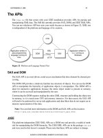
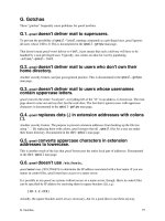
Figure 11.34 We find that Custom View 1 provides a nice view of the “set.” Your view is 45 degrees to the left and 45
degrees off the floor.
You now need to scale the layer back up so its apparent size
matches the original. Press S for Scale and scale the layer
up so it matches the other layers (when the edges match
the edge of the others). You may need to zoom your canvas
window to see your edges (Figure 11.35). Toggling the vis-
ibility for the reference image off and on, or leaving it set
to a low opacity for onion-skinning, makes this task easier.
Figure 11.33 If you have a very large
monitor, you may want to try the 4
Views options for more control.
Download from WoweBook.com
ptg
354
Chapter 11 Motion Control 2D and 3D
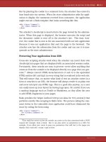
Figure 11.35 The scaled layer should line up with the others. You can change the label colors of the layers to make them
easier to see.
Repeat the scaling and positioning for the next layer.
Depending on the image, you may move this object farther
away or closer to the camera. You’re just trying to create
a sense of depth. Remember that you can switch views to
make it easier to see the arrangement of layers in Z space
(Figure 11.36). Don’t put as much distance between the
foreground and subject layers as you would between the
foreground and background layers. This effect should be
subtler. Remember to use your reference image (layer 2)
for checking alignment.
Using 3D Cameras
Animating the 3D cameras is pretty straightforward. In
fact, compared to other motion graphics projects motion
control 3D is much less abstract. You have a clear subject
and a reference source, which makes framing and compo-
sition much more clear-cut.
Figure 11.36 The Top and Custom
View 1 show the relationship between
Z-positions differently. Try using both for
an accurate assessment of the scene.
Setting the Reference layer to the
Difference blending mode is a
quick way to see what’s changed as
you scale and reposition layers.
Download from WoweBook.com
ptg
355
III: Design Exploration
Here are a few suggestions for getting the best results:
. Creating moves is much simpler when you’re using two
composition views. In one viewer you can see through
the viewfinder; the other lets you see your physical cam-
era. You can choose to use 2 Views - Vertical or 2 Views -
Horizontal depending on your monitors.
. When you select the camera layer in the Timeline
panel, you can see it in the second viewer. You can drag
and manipulate the camera right in the viewer.
. Set your starting frame first. Use the Camera Posi-
tion and Zoom controls. To move the camera, use a
combination of sliders and camera control handles. In
the canvas, you can grab the green arrow to move the
camera on the y-axis. Use the red arrow to move along
the x-axis and the blue arrow to move along the z-axis
(Figure 11.37).
. You’ll notice a line with a small crosshair circle. This
is the point of interest. Adjust this to affect where the
camera is pointed.
. Under the Camera Options category, you can keyframe
Zoom and Focus Distance (for zoom or rack focus ef-
fects). You can also adjust the aperture and blur level to
affect the depth of field. Be sure Depth of Field is turned
on for the most photorealistic results (Figure 11.38).
Figure 11.37 The camera handles
offer smooth control over camera
position and point of interest.
Yo u m a y n e e d t o p r e ss t h e
, (comma) or . (period) keys to
zoom out and see all. Hold down
the spacebar to move around the
window by dragging.
Yo u m a y w a nt t o l o c k y o ur l ay e rs
to avoid accidently moving them
when manipulating the camera.
Download from WoweBook.com
ptg
356
Chapter 11 Motion Control 2D and 3D
. Avoid more than a 45 degree move, or the scene will
likely fall apart. In fact, only subtle moves are needed
to get the most from this effect.
. RAM preview from time to time to see your results and
get a sense of timing and composition. To expedite
the experimental process, the initial preview should be
done at Quarter quality (Resolution setting in the Pre-
view panel or the Auto setting to match the resolution
set in the Composition panel).
Figure 11.38 Once Depth of Field is enabled, you’ll need to adjust the Focus Distance property. This will likely need to be key-
framed to compensate for a moving camera. You can see an actual box in the composition window that indicates where it is set.
. Create traditional camera moves like dollies and
pans to take advantage of the depth of field. To really
achieve parallax, be sure to introduce a slight angle to
the movement (which is caused by differences between
the camera position and the point of interest).
. You can add multiple cameras to a scene to try different
moves. Only the topmost camera will be used, or you can
control which one is active with visibility switches.
Advanced Techniques
The journey of creating motion control 3D is a bit of a nev-
er-ending wormhole. As soon as you master one technique,
you’ll discover new ones. The key to your sanity and budget
To cr ea te a rc ed ca me ra m ov es ,
select a keyframe in the Timeline.
Then in the canvas, you can click
with the Convert Vertex tool
(nested with the Pen tool) to
create Bezier handles. Adjust the
curve to taste.
Download from WoweBook.com
ptg
357
III: Design Exploration
is to combine techniques. Keep some shots simple and push
others to new heights. Here are three key technologies that
you can further explore to create fantastic effects.
Vanishing Point
Vanishing Point is tr uly a partnership feature (you’ll need
both Photoshop Extended and After Effects to pull off
this technique). It allows you to draw perspective planes
in Photoshop. Those planes should define major surfaces
or fields of view. You invoke Vanishing Point by choosing
Filter > Vanishing Point. Normally, you’d use it for perspec-
tive cloning, but with After Effects a cooler option exists.
The Vanishing Point Exchange feature relies on a visual
effects technique called photogrammetry, which is commonly
used to simplify 3D scenes. It assists in that not every object
has to be modeled. This significantly reduces the complex-
ity and time needed to create, render, and output a 3D
animation (Figure 11.39).
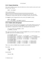
Figure 11.39 The ground and train station were turned into a simple 3D scene. The people were then inserted into the scene
at appropriate distances. Notice as the camera moves how elements interact differently due to their distance. The people are
perpendicular to the ground and can cast shadows.
Open a photo that you want to work with in Photoshop,
and then choose Filter > Vanishing Point. The Vanish-
ing Point interface opens. Start by drawing your first grid
inside the image. This should be the largest surface of the
object. Define the four corner nodes of the first plane sur-
face. The Create Plane tool is selected by default. Click the
preview image to define the four corner nodes.
Here are some general pointers for using Vanishing Point:
. Look for a straight line to use as a reference.
. Extend a bit beyond the boundaries to deal with peaks
or extruding objects.
We’ve found that Vanishing Point
Exchange works best when a photo
has an angle of about 45 degrees
with the subject. You should also
try to keep the frame as unob-
structed as possible. You can open
the files created by Vanishing Point
Exchange (VPE) into Photoshop to
clone or erase unwanted details.
Download from WoweBook.com
ptg
358
Chapter 11 Motion Control 2D and 3D
. You can tweak the first plane as much as needed.
. Try to use a rectangular object in the image as a guide
when creating the plane. You can zoom in with the
zoom controls in the bottom-left corner. Be sure to
line up each edge of the plane with the perspective of
the photo. Take your time on this step, because it’s the
most crucial part.
Once the first plane is created, you’ll need to generate the
second for the other surfaces. You can create a new plane
by holding down Command (Ctrl) and dragging from
the center of a plane’s edge. It’s critical that you “tear off”
planes rather than creating new ones so the model can stay
attached. Drag the handle so the plane extends beyond the
edge of the object. You’ll likely need to adjust the angle so
the second plane lines up. You can change the angle with
the controls in the top bar.
You can tear off planes for the floor or ground. If you’re
using multiple ground planes, be sure to adjust them so
they overlap. For this task, you’ll find it easiest to zoom out
and see some of the gray canvas space. Drag the handles
and resize the planes as needed (Figure 11.40).
Figure 11.40 Once created, the planes can be exported to After Effects through Vanishing Point Exchange.
Yo u c a n a l s o u s e th i s t e c hn i q u e t o
create surfaces for the floor and
sky when you’re dealing with a
horizon.
Download from WoweBook.com
ptg
359
III: Design Exploration
When you’re finished, click the submenu in the upper-left
corner, and then choose Export for After Effects (.vpe).
Create a new folder, which will serve as a destination for
the PNG files and 3D data that Photoshop will generate.
After the export is completed, click OK to store the Vanish-
ing Point information. You can then close and save the
Photoshop file. If you need to revisit the planes for tweak-
ing, just open the PSD filter and run the Vanishing Point
filter again; your previous planes will be there for editing.
Switch to After Effects and create a new project. Then
choose File > Import > Vanishing Point (.vpe). Navigate to
the folder you created, select the VPE file, and click Open.
After Effects creates a new composition, reassembles the
3D objects based on the VPE data, and arranges all the
planes (each an individual layer in the PNG format) in 3D
space (Figure 11.41).
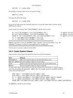
Figure 11.41 Vanishing Point Exchange was used to create a plane for the ground and the sky. The soldiers and tents were
then added back into the scene. Because they are perpendicular to the ground, the camera feels like it is moving across a
surface as it dollies.
Download from WoweBook.com
ptg
360
Chapter 11 Motion Control 2D and 3D
You can use the Orbit Camera tool (C) to rotate around
your scene:
. You can rotate about 40 degrees left or right before a
scene looks too fake.
. Be careful not to pull the camera too high in the frame,
or the object will look like a cutout doll.
. The individual PNG files can be cleaned up easily
in Photoshop. Select them one at a time and press
Command+E (Ctrl+E) to edit them. In Photoshop, use
cloning and erasing to clean up unwanted pixels or
blank areas. After fixing the files, close and save them
to return to After Effects.
. When you’re ready to animate, change the After Effects
composition settings to match your needs. Animate the
camera or null object to create the desired animation.
. Use the different views in After Effects to place multiple
elements correctly in the scene (Figure 11.42).
Figure 11.42 Changing the 3D view makes it simpler to see your scene. Use multiple views as you position cameras, lights,
and objects.
Puppet Tools
The Puppet tools can be used to quickly add natural mo-
tion to photos or vector artwork. The tools use an effect
(called the Puppet effect), which will automatically be ap-
plied when you use the tools. The Puppet effect warps the
image based on the positions of pins that you place (Figure
11.43). You can use pins to define which parts of an image
should move (or shouldn’t) and which parts should be in
front when other parts overlap.
Don’t change the canvas size when
touching up your PNG files. Instead,
if you want to extend the photo’s
edges, you should do that prior to
creating the Vanishing Point plane
in Photoshop.
Download from WoweBook.com
ptg
361
III: Design Exploration
Figure 11.43 The Puppet effect warps the position of the hands and allows the fingers of the statue to bend over time.
. Puppet Pin tool. Use this tool to place and move
Deform pins.
. Puppet Overlap tool. Use this tool to place Overlap pins,
which indicate which parts of an image should appear in
front of others when a distortion causes parts to overlap.
. Puppet Starch tool. Use this tool to place Starch pins.
These stiffen parts of the image so they are distorted
less by the warp.
Placing Pins
When you place the first pin, it applies the Puppet effect.
After Effects will automatically attempt to break the image
into a triangular mesh. You can see this mesh when a Pup-
pet tool pointer is over the area that the outline defines
(Figure 11.44).
The mesh and the image pixels are interconnected, so
moving the mesh will move the pixels. Here’s how the
controls work:
. If you move a Deform pin, the mesh changes shape.
After Effects attempts to keep the overall mesh as rigid
as possible to produce natural, lifelike movement.
. A layer can have multiple meshes. Add meshes if you
want to control distortion independently.
. The meshes do not recognize moving footage (such as
video) and will not update.
Puppet Overlap Controls
You can use the Puppet Overlap tool to apply Overlap pins.
This is a simple way to control apparent depth. You must
apply Puppet Overlap pins to the original outline. You
have two controls:
Figure 11.44 Place pins at logical
points. In this image a vise was made
using five pins. A pin was placed at
each fingertip, each joint where the
fingers connect to the hand, and one
in the bend of the wrist.
Download from WoweBook.com
ptg
362
Chapter 11 Motion Control 2D and 3D
. In Front. Shows the apparent proximity to the viewer.
In Front values are added together for places for the
mesh where extents overlap. You can also use negative
In Front values.
. Extent. Specifies how far from the Overlap pin its influ-
ence extends. The fill is dark if In Front is negative; the
fill is light if In Front is positive.
Puppet Starch Controls
When you’re distorting one part of an image, you may
want to prevent other parts from being distorted. The Pup-
pet Starch tool is used to apply Starch pins to keep parts
rigid. You must apply Puppet Starch pins to the original
outline (Figure 11.45). You have two controls:
. Amount. Specifies the strength of the stiffening. The
Amount values are added together for places on the
mesh where extents overlap. You can use negative
Amount values. Small Amount values are best for
preventing image tearing without introducing much
rigidity.
. Extent. Specifies how far from the Starch pin its influ-
ence extends. The Extent is indicated by a pale fill in
the affected parts of the mesh.
Sketching Motion with the Puppet Pin Tool
With Sketch, you can animate the motion path of one
or more Deform pins in realtime (or a specified speed).
This makes it effortless to create natural movement and
to sync it with audio or other elements. A quick way to
invoke Sketch is to hold down the Command (Ctrl) key
and sketch in realtime when you click and drag on a pin
(Figure 11.46).
Be sure to click Record Options in the Tools panel to ac-
cess the following options:
. Speed. This is the ratio of the speed of recorded mo-
tion compared to playback speed. If Speed is 100%, the
motion is played back at the same speed at which it was
recorded. If Speed is less than 100%, the motion plays
back faster than it was recorded. This is a useful way to
draw elaborate paths.
To sh ow t he Pu pp et m es h, se le ct
Show in the Tools panel.
Figure 11.45 The use of Starch pins
keeps the wrist from bending as the fin-
gers move. Be sure to adjust the Amount
and Extent settings to control rigidity.
Figure 11.46 The Sketch option takes
a little practice but is very organic.
Download from WoweBook.com
ptg
363
III: Design Exploration
. Smoothness. Try using a higher value to remove
extraneous keyframes from the motion path. It is
in fact better to have fewer keyframes if you want
smoother motion.
. Use Draft Deformation. If your system is lagging, try
this option. It will ignore Starch pins when sketching,
which improves system performance.
Enhancing the Scene
Would you like to take the techniques discussed in this
chapter further? There’s no end to the possible refine-
ments. Just remember to balance reality with created real-
ity. Here are a few modifications we make to truly make the
shots engaging.
Adding Lights
The use of lights in a scene can really add to the 3D na-
ture. You can use lights to enhance your scene and draw
the viewer’s eye to the area of interest. It’s important to
remember that lights add significantly to the render time.
We generally add them after the first draft renders have
been cut in by the editor and the timings are locked down.
Try introducing these types of light:
. Ambient light. Be sure to lower the overall lighting of
the scene before you add other lights. We typically set
an ambient light to around 80% to create a slightly
“darkened studio” effect that we can build on.
. Directional light. You can add other directional lights
to the scene that are motivated by existing lights. Think
about where the sun is, and then put a point or a spot
light there. Are there windows in a scene? Put a light on
the outside and have it shine through. Do you need to
cast shadows? Do so with lights (Figure 11.47).
. Volumet ric l ight . If you want to create lights that you
actually see (such as sunbeams) as opposed to lights
whose results you see (like shadows), check out Trap-
code Lux. This advanced plug-in works with the After
Effects lighting system and creates light that you can
point and see its beams.
Download from WoweBook.com
ptg
364
Chapter 11 Motion Control 2D and 3D
Figure 11.47 As the hands bend and cross each other, the light causes realistic shadows. Be sure to adjust the Cast
Shadows and Accepts Shadows properties to avoid unwanted shadows on your background.
Using Footage Plates
If you want to put a little more reality into your motion
control 3D, you’ll want to build up your footage library.
Be sure to build a healthy library of stock clips, especially
skies. We’ve also found that wide shots or urban areas
work well. The key here is to get some subtle motion into
the background that complements rather than distracts
(Figure 11.48).
Figure 11.48 Shooting time-lapse shots is a great way to make your own background plates for skies. Time-lapse motion offers a subtle
animation that complements motion control.
Download from WoweBook.com
ptg
365
III: Design Exploration
Creating your own time-lapse shots is pretty simple. You
can pick up an intervalometer to attach to a DSLR camera
for about $125 (Figure 11.49). This lets you set timings for
how often the camera records a shot. By locking down a
camera and shooting in manual mode, you can record a
new still. Typically, these stills are shot every 2–30 seconds
and can then be imported into After Effects as an image
sequence. These stills create gentle time-lapse shots that
work well for the background. You can stretch layers and
apply frame blending to smooth out the slowdown effect.
Creating Depth with Particles
A subtle element that we love to add to motion control
shots is particles (Figure 11.50). Although After Effects of-
fers several particle effects, we find the investment in Par-
ticular from Trapcode to be worthwhile. We use the effect
to add smoke, atmosphere, haze, and clouds. These effects
should be added after you’ve finished all other elements in
the shot because they take a while to render. The addition
is slight but often well worth it.
Figure 11.50 Columns of smoke were added to this scene for the smoke stacks and the burning buildings after a bomb attack.
The smoke has actual dimensionality, so as you rotate past it the clouds have depth.
Figure 11.49 Intervalometers are
often made for specific camera mod-
els. Be sure to check for compatibility
before ordering one.
You can visit
aetimelapsefor a video tutorial
on using After Effects to assemble
time-lapse movies. The technique
is explored in depth in the book
From Still to Motion: A Photogra-
pher’s Guide to Creating Video with
Yo u r D S L R (Peachpit Press, 2010).
We’ve included several of the shots
in this chapter on the book’s DVD.
Yo u ’l l f i n d b o t h p r o j e c t f i l e s a n d r e n -
dered movies. You’re also welcome
to check out the finished movie. See
the website www.bedfordthemovie.
comfor screening and ordering
information. The film is available on
Amazon.com as well.
Download from WoweBook.com
ptg
This page intentionally left blank
Download from WoweBook.com
ptg
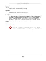
CHAPTER
12
Building with
Panoramic Images
Download from WoweBook.com
ptg
368
I knew the wild riders and the vacant land were about
to vanish forever and the more I considered the subject,
the bigger the forever loomed. Without knowing how to
do it, I began to record some facts around me, and the
more I looked, the more the panorama unfolded.
—Frederic Remington
Building with Panoramic Images
P
anoramic photography is the practice of shooting mul-
tiple photos and then stitching them into a larger photo. If
enough photos are taken, a large panoramic image can be
made. This process traditionally has used highly specialized
camera rigs and a lot of training.
At RHED Pixel, we got involved with panoramic photog-
raphy more than a decade ago. The ability to capture
wide vistas, enormous high-resolution photos, and sweep-
ing views was just too enticing. We also started to explore
QuickTime VR technology and focus on creating virtual
tours and interactive movies.
What does panoramic photography have to do with motion
graphics and visual effects? As it turns out, a lot. We first
began using our panoramic images to make large photos for
documentary-style motion control projects (Figure 12.1).
We started panning and scanning photos for long shots used
in video productions. But then a lightbulb went off.
Figure 12.1 The Photomerge command can bend images to create a composite image that lines up several photos into
a larger photo (left). The images can also be seamlessly blended together (right) to hide exposure variance.
Download from WoweBook.com
ptg
369
III: Design Exploration
We discovered that these images made great looping tex-
tures for seamless backgrounds or installation-style graph-
ics. When working with immersive environments (such as
nightclubs or retail), the images could be played on large
video walls as content.
Then Hollywood got in on the action as the green screen
frenzy took off for special effects. Entire scenes were being
created using photographic plates—sometimes as refer-
ence for 3D models, other times used “as is.” Panoramic
photos could then be brought into Adobe After Effects to
serve as a backdrop for chroma key footage. In fact, they
could even be turned into immersive environments for
360-degree sets.
What used to be a meticulous process is now ridiculously
easy. The Photomerge command in Adobe Photoshop is
incredibly effective and easily merges multiple images into
a seamless panorama.
Acquiring Panoramic Photos
Creating a panoramic photo requires multiple exposures.
Ideally, those photos will be taken from a stationary posi-
tion and be evenly distributed across an arc or circle as you
pan the camera. Pulling this off takes the right gear and
the right techniques.
Essential Gear
There are dedicated panoramic rigs that position the
camera so it is suspended above the tripod (so it floats over
its nodal point). They are designed to minimize distortion
and keep the camera precisely rotated. These rigs are quite
useful, but are not cheap. Although they are nice to have,
we find that Photoshop can easily correct for many of these
issues and the highly specialized gear is not needed.
However, what is essential is a tripod. You’ll want a tripod
with adjustable legs so you can easily level the tripod.
Some users merely tilt or cant a video-style tripod to level a
camera, but that won’t work when you’re shooting a wide-
angle image. As the camera pans, you’ll get a noticeable tilt
to the image. Being able to adjust the height of each leg
Download from WoweBook.com
ptg
370
Chapter 12 Building with Panoramic Images
becomes essential (Figure 12.2). You’ll know you’ve leveled
the camera by using a bubble level (many tripods have one
built in) (Figure 12.3).
Figure 12.2 Using adjustable legs lets you quickly level
the camera. For faster adjustments, we prefer latch-style
lags as opposed to couplings that have to be screwed
(and unscrewed).
Figure 12.3 A bubble level can quickly indicate if the
camera is level. This is essential to ensure that the pan-
oramic image doesn’t lean or tilt as you pan the camera.
Ideally, you’ll want to shoot in portrait mode. This allows
for the least amount of bending as you rotate the camera.
Essentially, you are creating a circle out of several rect-
angles. A portrait orientation allows for more sides to the
shape, hence a smoother curve. Unfortunately, most cam-
eras mount to their tripods in landscape mode.
One option is to look for a tripod with a tilting plate
(Figure 12.4). This works well but does introduce a slight
distortion to the image. A better option is to get an L-plate
for your camera. This makes it easy to rotate the camera
90 degrees. We use a plate and tripod mount (Figure 12.5)
from Really Right Stuff (www.ReallyRightStuff.com). Al-
though they are a premium grade, they offer plates made
to fit specific camera models precisely. Camera controls
and ports are not blocked by the L-plate.
Download from WoweBook.com
ptg
371
III: Design Exploration
Figure 12.4 Titling the tripod plate can create an unstable
camera and can add additional distortion because the
camera is off center.
Figure 12.5 An L-plate is a good compromise between
a dedicated panoramic rig and a standard tripod.
Pros know that it’s better to only slightly move the camera
to create overlapping images. There are specialized tripod
heads that you can purchase from companies like Kaidan
(www.kaidan.com) and Really Right Stuff that make leveling
and rotation even more precise. It is preferable for the tri-
pod head to have degrees marked on it to make your shoot-
ing more accurate as you rotate the camera (Figure 12.6).
Figure 12.6 We usually rotate
15 degrees when shooting pan-
oramic photos with a standard lens.
This produces 24 exposures for a full
360-degree panoramic and has
plenty of overlap for the Photomerge
command.
Download from WoweBook.com
ptg
372
Chapter 12 Building with Panoramic Images
Shooting Techniques
Capturing a professional-looking panoramic image is
easier than you might think. With a little practice, you can
make the technique repeatable and effortless. Fortunately,
modern DSLR cameras are very forgiving and even show
you their results before “developing.”
Great panoramas start with great photos. For the Photo-
merge command to work properly, we’ve provided some
guidelines for you to use when shooting. Here’s our recipe
to success:
1. Set up your tripod. Set up your tripod and make sure
the legs are spread wide enough for a stable base. Then
make sure the tripod is level. Photoshop can handle a
slight variance in angle, but more than a few degrees
can confuse the Photomerge command.
2. Go manual. Your camera should be in Manual mode.
You want to minimize changes in exposure as you pan
the camera. Be sure to keep your exposure constant
throughout all shots of the panorama. We recommend
taking a few test shots from around the arc and then
adjusting your settings.
3. Shoot raw. Camera raw formats offer much greater
control over exposure and significantly more image
detail to work with. If you have a tough exposure (like
strong directional lighting), raw files will help facilitate
a good result.
4. Shoot in portrait mode. You may need to get a special
bracket or tripod head to do this easily, but it’s well
worth it. Shooting in portrait mode minimizes hori-
zontal distortion and produces a panorama with the
maximum image quality.
5. Avoid distortion from the lens. You’ll want to avoid
using fish-eye lenses or other types of lenses that exces-
sively bend the image. If you do use a lens of this type,
choose the Auto layout option to minimize distortion
(Figure 12.7).
Download from WoweBook.com
ptg
373
III: Design Exploration
Figure 12.7 The merged image on the left uses the Perspective method and creates very different results than the
Auto method (right).
6. Focus on infinity. Be absolutely certain that you put the
camera into manual focus. You’ll want to focus at infin-
ity so everything stays the same through each shot.
7. Keep an eye on moving objects. If people or other
objects are moving through the frame, be sure to avoid
duplicating them in multiple exposures. If the scene
is quite busy, you should shoot each angle a few times.
You can always merge multiple exposures to remove an
object from a shot.
8. Overlap shots. The Photomerge command prefers an
overlap of 25–50 percent. Although some overlap is
good, too much can also be a problem. If Photoshop
encounters more than a 70 percent overlap, it may have
difficulty blending exposures.
9. Avoid focal length adjustments. Do not change your
focal length while shooting. If you’re using a fixed
lens, this is simple. However, you can still shoot with
a zoom lens. Just be sure you don’t adjust the lens
while shooting.
10. Precisely pan the camera. You’ll want to turn the cam-
era a consistent amount for each shot. The number of
exposures you’ll need will depend on your shooting
style and equipment.
Download from WoweBook.com
ptg
374
Chapter 12 Building with Panoramic Images
Capture Your Shots
Remember that the goal while shooting for a panoramic
image is to have consistent overlap from one shot to the
next. Photoshop detects these details so the shots can be
joined by the Photomerge command. Make sure there is at
least a 15 percent overlap between each shot. Depending
on the type of lens you use, you will need between 2 and
24 exposures. More exposures mean less distortion and
cleaner panoramic photos.
Portrait Aspect Ratio
Do your best to shoot in portrait mode (Figure 12.8), as
you’ll be able to minimize distortion by creating sizable
overlap. If you’re shooting a full 360-degree panoramic im-
age, turn the camera in 15-degree increments. This means
you will need to take 24 pictures for a complete loop.
Figure 12.8 Using 24 images, this panorama has plenty of overlap and results in a high-resolution photo.
Landscape Aspect Ratio
If a landscape orientation is your only option, you won’t
need as many exposures because of the wider images
(Figure 12.9). You can try shooting in 20-degree incre-
ments (18 pictures) or 30-degree increments (12 pictures).
Download from WoweBook.com
ptg
375
III: Design Exploration
Figure 12.9 In this shot, everything was done incorrectly. The camera was in landscape orientation, the shots were hand-
held, and the camera was in Aperture Priority mode. Still, the Photomerge command worked correctly and saved the day.
Handheld Shooting
What about handheld shooting for panoramic photos? The
official answer is no; don’t do it. However, at times we’ve
been inspired by a great view without having all our gear
with us. If you must shoot your panoramic images without
a tripod, you’ll need to adjust your handheld shooting
technique. In this case, use your body as a tripod.
Try wrapping the camera strap around your elbow or
shoulder (Figure 12.10). This allows you to place tension
on the strap so it is taut. The tension is a useful way to con-
strain the camera movement and make it more an exten-
sion of your body. Here are some guidelines for producing
the best handheld results:
Figure 12.10 Use your body and
camera strap to stabilize the camera.
Download from WoweBook.com
ptg
376
Chapter 12 Building with Panoramic Images
1. Hold the camera in front of your body so its strap hangs
downward.
2. Slip your arm through the strap so it goes just past
your elbow.
3. Wrap your hand around the outside edge of the strap
and grab the camera body.
4. Press your elbow into the strap to increase tension on
the strap and stabilize the camera.
To pan the camera smoothly, you’ll need to properly
position your body.
5. Square up your body with your subject.
6. Spread your feet shoulder-width apart.
7. Rotate at the waist and twist your body while keeping
your shoulders and camera in close to your body (mak-
ing sure there’s overlap between shots).
We’ve seen the Photomerge command deftly handle shots
that lacked a tripod’s support. Although we prefer to use
our gear, Photoshop has freed us to work without it when
necessary.
Photomerge Command
Photomerge is a specialized “mini-application” within
Photoshop that assists in combining multiple images into
a single photo. You can access it from either Photoshop
or Adobe Bridge. Depending on the resolution of your
sources and the speed of your machine, it can take a while
for Photomerge to complete stitching a panorama.
Organizing Images
As we’ve discussed throughout the book, using Bridge is a
great way to organize your photos (Figure 12.11). You can
readily group, rename, sort, and sift your images. We typi-
cally use Bridge to navigate to our panoramic photos, and
if needed to make selections between multiple exposures.
Chances are, you don’t need a
panoramic image that’s 30,000
pixels tall. If you’re shooting with a
high-resolution DSLR camera, don’t
be afraid to preprocess your pho-
tos. Use the Image Processor script
(File > Scripts > Image Processor)
to convert a group of images to
lower-resolution TIFF files. We
usually cap the image height to
3,000–5,000 pixels when we’re
working in HD.
Download from WoweBook.com