Multiple User InterfacesCross-Platform Applications and Context-Aware Interfaces phần 2 ppsx
Bạn đang xem bản rút gọn của tài liệu. Xem và tải ngay bản đầy đủ của tài liệu tại đây (625.64 KB, 42 trang )
16 AHMED SEFFAH AND HOMA JAVAHERY
trade-off that the user would be willing to make in return for the benefits of being able
to use the system in mobile contexts.
• Conformity to default UI standards: It is not necessary for all features to be made
available on all devices. For example, a PDA interface could eliminate images or it
might show them in black and white. Similarly, text can be abbreviated on a small
display, although it should be possible to retrieve the full text through a standard-
ized command.
These characteristics and constraints are not artefacts of current development technologies,
but are intrinsic to the MUI concept. Together, they characterize a MUI and complicate
its development.
2.1.3. VERTICAL VERSUS HORIZONTAL USABILITY
MUI usability issues can be considered to have two dimensions: vertical and horizontal.
Vertical usability refers to usability requirements specific to each platform while horizontal
usability is concerned with cross-platform usability requirements.
Many system manufacturers have issued design guidelines to assist designers in devel-
oping usable applications. These guidelines can be categorized according to whether they
advocate a design model (i.e. “do this”) or whether they discourage a particular imple-
mentation (i.e. “don’t do this”). For the PalmOS platform (www.palmsource.com), several
design guidelines address navigation issues, widget selection, and use of specialized input
mechanisms such as handwriting recognition. Microsoft Corporation has also published
usability guidelines to assist developers with programming applications targeted at the
Pocket PC platform. However, ‘give the user immediate and tangible feedback during
interaction with an application’ is either too general or too simplistic. In many cases,
the use of several different guidelines could create inconsistencies. Guidelines can come
into conflict more than usual, and making a trade-off can become an unsolvable task for
MUI developers.
Sun’s guidelines for the Java Swing architecture () describe a look-
and-feel interface that can overcome the limitations of platform-dependent guidelines.
However, these guidelines do not take into account the distinctiveness of each device,
and in particular the platform constraints and capabilities. An application’s UI components
should not be hard-coded for a particular look-and-feel. The Java PL&F (Pluggable Look
and Feel) is the portion of a Swing component that deals with its appearance (its look );
it is distinguished from its event-handling mechanism (its feel ). When you run a Swing
program, it can set its own default look by simply calling a UIManager method named
setLookAndFeel.
2.1.4. RELATED WORK
Remarkably, although research on MUIs and multi-device interaction can be traced to
the early 1980s, there are relatively few examples of successful implementations [Grudin
1994]. Perhaps the main cause of this poor success rate is the difficulty of integrating the
overwhelming number of technological, psychological and sociological factors that affect
MUI usability into a single unified design.
MULTIPLE USER INTERFACES: CROSS-PLATFORM APPLICATIONS AND CONTEXT-AWARE INTERFACES 17
In the evolution of user interfaces, a multi-user interface has been introduced to support
groups of devices and people cooperating through the computer medium [Grudin 1994].
A single user in the context of a MUI corresponds to a group of users for a multi-user
interface. The user is asynchronously collaborating with himself/herself. Even if the user
is physically the same person, he/she can have different characteristics while working
with different devices. For example, a mobile user is continuously in a rush, impatient,
and unable to wait [Ramsay and Nielsen 2000]. This user needs immediate, quick, short
and concise feedback. In the office, the same user can afford to wait a few seconds more
for further details and explanations.
The MUI domain can benefit from the considerable number of studies done in the area
of context-aware (or context-sensitive) user interfaces. This is still an active research topic,
with many emerging models such as plastic user interfaces [Thevenin and Coutaz 1999]
and the moderator model [Vanderdonckt and Oger 2001]. In a recent essay, Winograd
[2001] compared different architectures for context of use. As characterized in the previous
section, a MUI is a context-sensitive UI. This does not mean that a MUI should adapt
itself magically at run-time to the context of use (and in particular to platform capabilities
and constraints). The MUI can be either adaptive or adaptable. As we will discuss in the
next section, the adaptation can be done during specification, design or development by
the developer. The adaptation can also occur before or after deployment, either by the
end-user or the developer.
The concept of a compound document is also a useful technology that can support
the development and integration of the different views that form a MUI. A compound
document framework can act as a container in which a continuous stream of various
kinds of data and components can be placed [Orfali et al. 1996]. To a certain extent,
a compound document is an organized collection of user interfaces that we consider as
a specialization of a MUI. Each content form has associated controls that are used to
modify the content in place. During the last decade, a number of frameworks have been
developed such as Andrew, OLE, Apple OpenDoc, Active X and Sun Java Beans.
Compound document frameworks are important for the development of a MUI for
several reasons. They allow the different parts of a MUI to co-exist closely. For example,
they keep data active from one part to another, unlike the infamous cut and paste. They
also eliminate the need for an application to have a viewer for all kinds of data; it is
sufficient to invoke the right functionality and/or editor. Views for small devices do not
have to implement redundant functions. For example, there is no need for Microsoft
Word to implement a drawing program; views can share a charting program. Compound
document frameworks can also support asynchronous collaboration between the different
views and computers.
McGrenere et al. [2002] illustrate the use of two versions of the same application with
two different user interfaces as follows:
One can imagine having multiple interfaces for a new version of an application;
for example, MS-Word 2000 could include the MS-Word 97 interface. By allowing
users to continue to work in the old interface while also accessing the new interface,
they would be able to transition at a self-directed pace. Similarly, multiple interfaces
might be used to provide a competitor’s interface in the hopes of attracting new
18 AHMED SEFFAH AND HOMA JAVAHERY
customers. For example, MS-Word could offer the full interface of a word processor
such as Word Perfect (with single button access to switch between the two), in order
to support users gradually transitioning to the Microsoft product.
Our definition of a MUI is different from McGrenere’s definition. The common basis
is the fact that the user is exposed to two variations of the same interface. McGrenere
considers only the variations, which are referred to as versions, for the same computing
platform; while in our definition, the two variations can be either for the same computing
platform or for different ones.
2.2. FERTILE TOPICS FOR RESEARCH
EXPLORATION
We will now discuss promising development models that can facilitate MUI development
while increasing their usability. This section of the paper is highly speculative and will
raise far more fundamental research questions than it will provide answers. Furthermore,
this is a selective list of topics, and not exhaustive. Our goal is to give researchers a
glimpse of the most important problems surrounding potential MUI development models.
In the migration of interactive systems to new platforms and architectures, many mod-
ifications have to be made to the user interface. As an example, in the process of adapting
the traditional desktop GUI to other kinds of user interfaces such as Web or handheld
user interfaces, most of the UI code has to be modified. In this scenario, UI model-based
techniques can drive the reengineering process. Reverse engineering techniques can be
applied, resulting in a high-level model of the UI. This model can then be used to help
reengineer the user interface.
2.2.1. CONTEXT-AWARE DEVELOPMENT
Context-aware UI development refers to the ability to tailor and optimize an interface
according to the context in which it is used. Context-aware computing as mentioned
by Dey and Abowd refers to the “ability of computing devices to detect and sense,
interpret and respond to, aspects of a user’s local environment and the computing devices
themselves” [Dey and Abowd 2000]. Context-aware applications dynamically adapt their
behaviour to the user’s current situation, and to changes of context of use that might
occur at run-time, without explicit user intervention. Adaptation requires a MUI to sense
changes in the context of use, make inferences about the cause of these changes, and then
to react appropriately.
Two types of adaptation have to be considered for MUIs:
• Adapting to technological variety Technological variety implies supporting a broad
range of hardware, software, and network access. The first challenge in adaptation
is to deal with the pace of change in technology and the variety of equipment that
users employ. The stabilizing forces of standard hardware, operating systems, network
protocols, file formats and user interfaces are undermined by the rapid pace of tech-
nological change. This variety also results in computing devices (e.g. mobile phones)
MULTIPLE USER INTERFACES: CROSS-PLATFORM APPLICATIONS AND CONTEXT-AWARE INTERFACES 19
that exhibit drastically different capabilities. For example, PDAs use a pen-based input
mechanism and have average screen sizes around three inches. In contrast, the typ-
ical PC uses a full sized keyboard and a mouse and has an average screen size of
17 inches. Coping with such drastic variations implies much more than mere layout
changes. Pen-based input mechanisms are slower than traditional keyboards and are
therefore inappropriate for applications such as word processing that require intensive
user input.
• Adapting to diversity in context of use Further complications arise from accommodat-
ing users with different skills, knowledge, age, gender, disabilities, disabling condi-
tions (mobility, sunlight, noise), literacy, culture, income, etc. [Stephanidis 2002]. For
example, while walking down the street, a user may use a mobile phone’s Internet
browser to look up a stock quote. However, it is highly unlikely that this same user
would review the latest changes made to a document using the same device. Rather, it
would seem more logical and definitely more practical to use a full size computer for
this task. It would therefore seem that the context of use is determined by a combina-
tion of internal and external factors. The internal factors primarily relate to the user’s
attention while performing a task. In some cases, the user may be entirely focused
while at other times, the user may be distracted by other concurrent tasks. An example
of this latter point is that when a user is driving a car, he/she cannot use a PDA to
reference a telephone number. External factors are determined to a large extent by the
device’s physical characteristics. It is not possible to make use of a traditional PC as
one walks down the street. The same is not true for a mobile telephone. The challenge
to the system architect is thus to match the design of a particular device’s UI with the
set of constraints imposed by the corresponding context of use.
A fundamental question is when should a MUI be tailored as a single and unique
interface? The range of strategies for adaptation is delimited by two extremes. Interface
adaptation can happen at the factory, that is, developers produce several versions of an
application tailored according to different criteria. Tailoring can also be done at the user’s
side, for instance, by system administrators or experienced users. At the other extreme,
individual users might tailor the interfaces themselves, or the interface could adapt on
its own by analyzing the context of use. The consensus from our workshop was that the
adaptation of a MUI should be investigated at different steps of the deployment lifecycle
[Seffah et al. 2001]:
• User customization after deployment Here, tailoring operations are the entire responsi-
bility of the user. While this laissez-faire approach avoids the need for system support,
it lacks a central arbitrator to resolve incompatible and inconsistent preferences between
devices. The arbitrator should have the ability to make global changes (cross-platform
changes) based on local adaptations. This makes MUIs more difficult to write, and the
adaptation fails to repay the development cost of support.
• Automatic adaptation at run-time The idea is to write one UI implementation that
adapts itself at run-time to any computing platform and context of use. The drawback
of this strategy is that there may be situations where adaptation performed by the system
is inadequate or even counterproductive.
20 AHMED SEFFAH AND HOMA JAVAHERY
• Just-in-time customization during development or deployment Developers can use a
high-level language to implement an abstract and device-independent UI model. Then,
using a rendering tool, they can generate the code for a specific platform. The User
Interface Markup Language, UIML [Abrams and Phanouriou 1999], and the eXtensi-
ble Interface Markup Language, XIML [Eisenstein et al. 2001], aim to support such
an approach.
• Customization during design and specification This approach requires the development
of an appropriate design methodology and multi-platform terminology to properly build
a task model of a MUI. This model may be expressed in one or more notations. Tailoring
can be done at the stage of abstract interface specification where the dialogue gets
modified, for example to shortcut certain steps, to rearrange the order for performing
steps, etc.
Efforts have already begun to develop frameworks that support the building of context-
aware applications. The Context Toolkit [Dey and Abowd 2000] is an infrastructure that
supports the rapid development of context-aware services, assuming an explicit descrip-
tion of a context. This framework’s architecture enables the applications to obtain the
context they require without knowledge about how the context was sensed. The Context
Toolkit consists of context widgets that implicitly sense context, aggregators that collect
related context, interpreters that convert between context types and interpret the context,
applications that use context and a communications infrastructure that delivers context
to these distributed components. The toolkit makes it easy to add the use of context or
implicit input to existing applications.
2.2.2. MODEL-BASED DEVELOPMENT
Model-based approaches for UI development [Bomsdorf and Szwillus 1998; M
¨
uller et al.
2001] exploit the idea of using declarative interface models to drive the interface devel-
opment process. An interface model represents all the relevant aspects of a UI using a
user interface modelling language. Model-based development approaches attempt to auto-
matically produce a concrete UI design (i.e. a concrete presentation and dialogue for a
specific platform) from the abstract “generic” representation of the UI (i.e., generic task,
domain and dialogue model). This is done by mapping the abstract model onto the con-
crete user interface or some of its elements [Bomsdorf and Szwillus 1998]. For example,
given user task t in domain d, the mapping process will find an appropriate presentation p
and dialogue D that allows user u to accomplish t. Therefore, the goal of a model-based
system in such a case is to link t,d,andu with an appropriate p and D. Model-based UI
development could be characterized as a process of creating mappings between elements
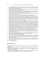
in various model components. The process of generating the concrete interface and UI
model involves levels as shown in Figure 2.3.
Model-based approaches, in particular the related automatic or semi-automatic UI
generation techniques, are of interest to MUI development. UI modelling will be an
essential component of any effective long-term approach to developing MUIs. Increased
user involvement in the UI development process will produce more usable UI models.
Model-based UI systems take an abstract model of the UI and apply design rules and data
MULTIPLE USER INTERFACES: CROSS-PLATFORM APPLICATIONS AND CONTEXT-AWARE INTERFACES 21
UI models
Generic UI specification
Concrete UI specification
Generic task, domain and dialog
models
Concrete task, domain and
dialogue models
Figure 2.3. Examples of models and mappings in model-based development.
about the application to generate an instance of the UI. Declarative model-based tech-
niques use UI modelling techniques for abstractly describing the UI. A formal, declarative
modelling language should express the UI model.
Current model-based techniques, which most frequently use task and domain models,
do not generate high-quality interfaces. Furthermore, task analysis is performed to obtain
a single UI that is adapted for a single context of use. We need to model tasks that can be
supported in multiple contexts of use, considering multiple combinations of the contextual
conditions. Knowledge bases for domain, presentation, dialogue, platform and context of
use need to be exploited to produce a usable UI that matches the requirements of each
context of use.
UI models that support mobility contain not only the visual look-and-feel of the UI,
but also semantic information about the interface. The model-based techniques proposed
for mobile UIs range from relatively low-level implementation solutions, such as the
use of abstract and concrete interactor objects, to high-level task-based optimization of
the interface’s presentation structure. UI models should factor out different aspects of UI
design that are relevant to different contexts of use and should isolate context-independent
issues from context-specific ones.
As a starting point for research in the field of model-based development for MUIs,
the focus should be on task-based models [Patern
`
o 2001]. Such models can foster the
emergence of new development approaches for MUIs, or at least help us to better under-
stand the complexity of MUI development. A task model describes the essential tasks that
the user performs while interacting with the UI. A typical task model is a hierarchical
tree with sub-trees indicating the tasks that the user can perform. Task models are a very
convenient specification of the way problems can be solved.
Early investigations show that in the case of a MUI, we should make a distinction
between four kinds of task models [M
¨
uller et al. 2001]: general task models for the
problem domain, general task models for software support, device-dependent task models
22 AHMED SEFFAH AND HOMA JAVAHERY
and environment-dependent task models. The general task model for the problem domain
is the result of a very detailed analysis of the problem domain. It describes how a problem
can be tackled in general. All relevant activities and their temporal relations are described.
Such a model can be considered as the representation of an expert’s knowledge. The state
of the art for the problem domain is captured within this model.
Certain approaches transform whole applications from one platform to another one
without considering the tasks that will be supported. However, sometimes it is wise to
look at the tasks first and to decide which tasks a device can support optimally. This
information is captured in the device-dependent task model. The environment-dependent
task model is the most specific one. It is based on design decisions in previous models
and describes computer-supported tasks for a given device. This model describes the
behaviour of a system based on the available tools, resources, and the abilities of the
user. It can be interpreted statically (environmental influences are defined during design
time) or dynamically (environmental influences are evaluated during run-time).
2.2.3. PATTERN-DRIVEN DEVELOPMENT
In the field of UI design, a pattern encapsulates a proven solution for a usability problem
that occurs in various contexts of use. As an illustration, the convenient toolbar pattern
(used on web pages) provides direct access to frequently used pages or services. This
pattern, also called Top Level Navigation [Tidwell 1997], can include navigation con-
trols for News, Search, Contact Us, Home Page, Site Map, etc. UI design patterns can
be used to create a high-level design model, and can therefore facilitate the develop-
ment and validation of MUIs. Discussion of patterns for software design started with the
software engineering community and now the UI design community has enthusiastically
taken up discussion of patterns for UI design. Many groups have devoted themselves to
the development of pattern languages for UI design and usability. Among the heteroge-
neous collections of patterns, those known as Common Ground, Experience, Brighton,
and Amsterdam play a major role in this field and have significant influence [Tidwell
1997; Borchers 2000]. Patterns have the potential to support and drive the whole design
process of MUIs by helping developers select proven solutions of the same problem for
different platforms.
Pattern-driven development should not be considered as an alternative approach to
model-based and context-aware development. In the context of MUI development, patterns
can complement a task model by providing best experiences gained through end-user
feedback. Furthermore, patterns are suitable for transferring knowledge from usability
experts to software engineers who are unfamiliar with MUI design, through the use
of software tools. For instance, CASE tools have long been available to assist software
developers in the integration of the many aspects of web application prototyping [Javahery
and Seffah 2002].
However, the natural language medium generally used to document patterns, coupled
with a lack of tool support, compromises these potential uses of patterns, as well as the
pattern-oriented design approach. These well-known weaknesses of UI patterns should
motivate researchers to investigate a systematic approach to support both pattern writ-
ers and users alike by automating the development of pattern-assisted design. We should
MULTIPLE USER INTERFACES: CROSS-PLATFORM APPLICATIONS AND CONTEXT-AWARE INTERFACES 23
also provide a framework for automating the development of pattern-oriented design. The
motivation of such automation is to help novice designers apply patterns correctly and effi-
ciently when they really need them. One approach to pattern-oriented design automation
is being able to understand during the design process when a pattern is applicable, how it
can be applied, and how and why it can or cannot be combined with other related patterns.
2.2.4. DEVICE-INDEPENDENT DEVELOPMENT
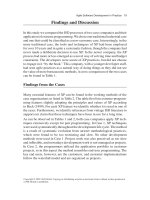
Currently, different development languages are available (Figure 2.4). Under the umbrella
of platform-dependent languages, we classify the wide variety of existing mark-up lan-
guages for wireless devices such as the Wireless Markup Language (WML) or the light
HTML version. These languages take into account the platform constraints and capabil-
ities posed by each platform. They also suggest specific design patterns for displaying
information and interacting with the user in specific ways for each device.
Platform-independent languages are mainly based on UI modelling techniques. Their
goal is to allow cross-platform development of UIs while ensuring consistency not only
between the interfaces on a variety of platforms, but also in a variety of contexts of
use. They provide support for constraints imposed not only by the computing platforms
themselves, but also by the type of user and by the physical environment. They should
help designers recognize and accommodate each context in which the MUI is being
used. Such languages provide basic mechanisms for UI reconfigurations depending on
variations of the context of use. They address some of the problems raised by context-
aware development.
XML-based languages such as XIML and UIML are promising candidates for MUI
development. Some of the reasons are that such XML-based languages:
• Can contain constraint definitions for the XML form itself, and also for the exter-
nal resources;
• Allow the separation of UI description from content, by providing a way to spec-
ify how UI components should interact and a way to spell out the rules that define
interaction behaviour;
Assembly language
High-level programming language (C, C++, etc.)
Platform-dependent mark-up language (WML, etc.)
Platform-independent markup and model-based
language (XIML, UIML)
Scripting language (VB, PERL, etc.)
Figure 2.4. Evolution of UI development languages.
24 AHMED SEFFAH AND HOMA JAVAHERY
• Provide an abstraction level that allows the UI to adapt to a particular device or set of
user capabilities;
• Support model-based development.
MUI design pattern implementations should exist in various languages and platforms.
Rather than using different programming languages for coding the different implemen-
tations, we should use an XML-based notation as a unified and device-independent
language for documenting, implementing and customizing MUI design patterns. By using
XML-compliant implementations, patterns can be translated into scripts for script-based
environments like HTML authoring tools, beans for Java GUI builders like VisualAge,
and pluggable objects like Java applets and ActiveX components. Generating a specific
implementation from an XML-based description is now possible because of the availabil-
ity of XML-based scripting languages. Among them, we consider UIML and XIML as
potential candidates.
UIML and XIML languages permit a declarative description of a UI in a highly device-
independent manner. They allow portability across devices and operating systems, and
use a style description to map the interface to various operating systems and devices.
UIML separates the UI content from its appearance. UIML does this by using a device-
independent UI definition to specify the UI content and a device-dependent style sheet
that guides the placement and appearance of the UI elements. UIML descriptions of a
UI can be rendered in HTML, Java and WML. Tools that generate the code from design
patterns, such as the IBM-Automatic code generator [Budinsky et al. 1996], are a starting
point for automating the development of pattern-oriented design. Furthermore, using an
XML-based language for documenting patterns has already been explored. However, the
XML-based descriptions force all pattern writers and users to closely adhere to and master
a specific format and terminology for documenting and implementing patterns.
2.3. CONCLUDING REMARKS
Understanding MUIs is essential in our current technological context. A MUI imposes
new challenges in UI design and development since it runs on different computing plat-
forms accommodating the capabilities of various devices and different contexts of use.
Challenges are also presented because of the universal access requirements for a diversity
of users. The existing approaches to designing one user interface for a single user profile
for one computing platform do not adequately address the MUI challenges of diversity,
cross-platform consistency, universal accessibility and integration. Therefore, there is an
urgent need for a new integrative framework for modelling, designing, and evaluating
MUIs for the emerging generation of interactive systems.
As outlined in this chapter, effective MUI development should combine different mod-
els and approaches. MUI architectures that neglect these models and approaches cannot
effectively meet the requirements of the different users. Unfortunately, adoption of a
MUI application is contingent upon the acceptance of all of the stakeholders. Researchers
should focus on ways to assist developers in creating effective MUI designs for a large
MULTIPLE USER INTERFACES: CROSS-PLATFORM APPLICATIONS AND CONTEXT-AWARE INTERFACES 25
variety of computing platforms. Existing methods work well for regular software devel-
opment and have thus been adapted for MUIs. However, these methods usually result
in tools that do not capture the full complexity of the task. Pattern hierarchies seem to
be an exception to this finding. Whereas an individual pattern provides a solution to a
specific problem, hierarchically organized patterns guide the developer through the entire
architectural design. In this way, they enforce consistency among the various views and
break down complex decisions into smaller, more comprehensible steps.
ACKNOWLEDGEMENTS
We thank Dr. Peter Forbrig for his contribution to the MUI effort.
REFERENCES
Abrams, M. and Phanouriou, C. (1999) UIML: An XML Language for Building Device-Independent
User Interfaces. Proceedings of XML 99, December 1999, Philadelphia.
Bomsdorf, B. and Szwillus, G. (1998) From Task to Dialogue: Task-Based User Interface Design.
SIGCHI Bulletin, 30(4).
Borchers, J.O. (2000) A Pattern Approach to Interaction Design. Proceedings of the DIS 2000
International Conference on Designing Interactive Systems, August 16–19, 2000, 369–78. New
York, ACM Press.
Budinsky, F., Finnie, F.J., Vlissides, J.M. and Yu, P.S. (1996) Automatic Code Generation from
Design Patterns. Object Technology, 35(2).
Dey, A.K. and Abowd, G.D. (2000). Towards a Better Understanding of Context and Context-
Awareness. Proceedings of the CHI’2000 Workshop on Context Awareness. April 1–6, 2000, The
Hague, Netherlands.
Eisenstein, J., Vanderdonckt, J. and Puerta, A. (2001) Applying Model-Based Techniques to the
Development of UIs for Mobile Computers. Proceedings of the ACM Conference on Intelligent
User Interfaces, IUI’2001, January 11– 13, 2001, 69–76. New York, ACM Press.
Ghani, R. (2001) 3G: 2B or not 2B? The potential for 3G and whether it will be used to its full
advantage. IBM Developer Works: Wireless Articles, August 2001.
Grudin, J. (1994) Groupware and Social Dynamics: Eight Challenges for Developers. Communica-
tions of the ACM, 37(1), 92–105.
Javahery, H. and Seffah, A. (2002) A Model for Usability Pattern-Oriented Design. Proceedings of
the Conference on Task Models and Diagrams for User Interface Design, Tamodia’2002, July
18–19 2002, Bucharest, Romania.
McGrenere, J., Baecker, R. and Booth, K. (2002) An Evaluation of a Multiple Interface Design
Solution for Bloated Software. Proceedings of ACM CHI, 2002, April 20–24, 2002, Minneapolis,
USA.
M
¨
uller, A., Forbrig, P. and Cap, C. (2001) Model-Based User Interface Design Using Markup Con-
cepts. Proceedings of DSVIS 2001, June 2001, Glasgow, UK.
Ramsay, M. and Nielsen, J. (2000) WAP Usability D´ej`a Vu: 1994 All Over Again. Report from a
Field Study in London. Nielsen Norman Group, Fremont, USA.
Orfali, R., Harkey, D. and Edwards, J. (1996) The Essential Distributed Objects Survival Guide.
John Wiley & Sons Ltd., New York.
Patern
`
o, F. (2001) Task Models in Interactive Software Systems in Handbook of Software Engi-
neering & Knowledge Engineering (ed. S.K. Chang). World Scientific Publishing Company.
Seffah, A., Radhakrishan T. and Canals, G. (2001) Multiple User Interfaces over the Internet: Engi-
neering and Applications Trends. Workshop at the IHM-HCI: French/British Conference on
Human Computer Interaction, September 10–14, 2001, Lille, France.
26 AHMED SEFFAH AND HOMA JAVAHERY
Stephanidis, C. (ed) (2002) User Interfaces for all: Concepts, Methods, and Tools. Lawrence Erl-
baum Associates Inc., Mahwah, USA.
Thevenin, D. and Coutaz, J. (1999) Plasticity of User Interfaces: Framework and Research Agenda.
Proceedings of IFIP TC 13 International Conference on Human-Computer Interaction, Inter-
act’99, 110–117, August 1999 (eds A. Sasse and C. Johnson), Edinburgh, UK. IOS Press,
London.
Tidwell, J. (1997) Common Ground: A Pattern Language for Human-Computer Interface Design.
/>Vanderdonckt, J. and Oger, F. (2001) Synchronized Model-Based Design of Multiple User
Interfaces. Workshop on Multiple User Interfaces over the Internet: Engineering and Applications
Trends. IHM-HCI: French/British Conference on Human Computer Interaction, September
10–14, 2001, Lille, France.
Winograd, T. (2001) Architectures for Context. Human-Computer Interaction, 16, 2–3.
Part II
Adaptation and Context-Aware
User Interfaces
3
A Reference Framework for
the Development of Plastic
User Interfaces
David Thevenin, Jo
¨
elle Coutaz, and Ga
¨
elle Calvary
CLIPS-IMAG Laboratory, France
3.1. INTRODUCTION
The increasing proliferation of fixed and mobile devices addresses the need for ubiquitous
access to information processing, offering new challenges to the HCI software community.
These include:
• constructing and maintaining versions of the user interface across multiple devices;
• checking consistency between versions to ensure a seamless interaction across multi-
ple devices;
• designing the ability to dynamically respond to changes in the environment such as
network connectivity, user’s location, ambient sound and lighting conditions.
These requirements create extra costs in development and maintenance. In [Thevenin
and Coutaz 1999], we presented a first attempt at cost-justifying the development process
Multiple User Interfaces. Edited by A. Seffah and H. Javahery
2004 John Wiley & Sons, Ltd ISBN: 0-470-85444-8
30 DAVID THEVENIN, JO
¨
ELLE COUTAZ, AND GA
¨
ELLE CALVARY
of user interfaces using the notion of plasticity as a fundamental property for user inter-
faces. The term plasticity is inspired from materials that expand and contract under natural
constraints without breaking, thus preserving continuous usage. Applied to HCI, plasticity
is the “capacity of an interactive system to withstand variations of contexts of use while
preserving usability” [Thevenin and Coutaz 1999].
Adaptation of user interfaces is a challenging problem. Although it has been addressed
for many years [Thevenin 2001], these efforts have met with limited success. An impor-
tant reason for this situation is the lack of a proper definition of the problem. In this
chapter, we propose a reference framework that clarifies the nature of adaptation for
plastic user interfaces from the software development perspective. It includes two com-
plementary components:
• A taxonomic space that defines the fundamental concepts and their relations for rea-
soning about the characteristics and requirements of plastic user interfaces;
• A process framework that structures the software development of plastic user interfaces.
Our taxonomic space, called the “plastic UI snowflake” is presented in Section 3.3, fol-
lowed in Section 3.4 by the description of the process framework. This framework is then
illustrated in Section 3.5 with ARTStudio, a tool that supports the development of plastic
user interfaces. In Section 3.2, we introduce the terminology used in this chapter. In par-
ticular, we explain the subtle distinction between plastic user interfaces and multi-target
user interfaces in relation to context of use.
3.2. TERMINOLOGY: CONTEXT OF USE, PLASTIC UI
AND MULTI-TARGET UI
Context is an all-encompassing term. Therefore, to be useful in practice, context must
be defined in relation to a purpose. The purpose of this work is the adaptation of user
interfaces to different elements that, combined, define a context of use. Multi-targeting
focuses on the technical aspects of user interface adaptation to different contexts of use.
Plasticity provides a way to characterize system usability as adaptation occurs. These
concepts are discussed next.
3.2.1. CONTEXT OF USE AND TARGET
The context of use denotes the run-time situation that describes the current conditions of
use of the system. A target denotes a situation of use as intended by the designers during
the development process of the system.
The context of use of an interactive system includes:
• the people who use the system;
• the platform used to interact with the system;
• the physical environment where the interaction takes place.
A REFERENCE FRAMEWORK FOR THE DEVELOPMENT OF PLASTIC USER INTERFACES 31
A target is defined by:
• the class of user intended to use the system;
• the class of platforms that can be used to interact with the system;
• The class of physical environments where the interaction is supposed to take place.
In other words, if at run-time the context of use is not one of the targets envisioned during
the design phase, then the system is not able to adapt to the current situation (person,
platform, physical environment).
A platform is modelled in terms of resources, which in turn determine the way
information is computed, transmitted, rendered, and manipulated by users. Examples
of resources include memory size, network bandwidth and input and output interactive
devices. Resources motivate the choice of a set of input and output modalities and, for
each modality, the amount of information made available. Typically, screen size is a
determining factor for designing web pages. For DynaWall [Streitz et al. 1999], the plat-
form includes three identical wall-sized tactile screens mounted side by side. Rekimoto’s
augmented surfaces are built from a heterogeneous set of screens whose topology may
vary: whereas the table and the electronic whiteboard are static surfaces, laptops may be
moved around on top of the table [Rekimoto and Saitoh 1999]. These examples show
that the platform is not limited to a single personal computer. Instead, it covers all of the
computational and interactive resources available at a given time for accomplishing a set
of correlated tasks.
An environment is ‘a set of objects, persons and events that are peripheral to the current
activity but that may have an impact on the system and/or users behaviour, either now or
in the future’ [Coutaz and Rey 2002]. According to this definition, an environment may
encompass the entire world. In practice, the boundary is defined by domain analysts. The
analyst’s role includes observation of users’ practice [Beyer 1998; Cockton et al. 1995;
Dey et al. 2001; Johnson et al. 1993; Lim and Long 1994] as well as consideration of
technical constraints. For example, environmental noise should be considered in relation
to audio feedback. Lighting condition is an issue when it can influence the reliability of
a computer vision-based tracking system [Crowley et al. 2000].
3.2.2. MULTI-TARGET USER INTERFACES AND PLASTIC USER INTERFACES
A multi-target user interface is capable of supporting multiple targets. A plastic user
interface is a multi-target user interface that preserves usability across the targets. Usability
is not intrinsic to a system. Usability must be validated against a set of properties elicited
in the early phases of the development process. A multi-target user interface is plastic
if these usability-related properties are kept within the predefined range of values as
adaptation occurs to different targets. Although the properties developed so far in HCI
[Gram and Cockton 1996] provide a sound basis for characterizing usability, they do not
cover all aspects of plasticity. In [Calvary et al. 2001a] we propose additional metrics for
evaluating the plasticity of user interfaces.
Whereas multi-target user interfaces ensure technical adaptation to different contexts
of use, plastic user interfaces ensure both technical adaptation and usability. Typically,
32 DAVID THEVENIN, JO
¨
ELLE COUTAZ, AND GA
¨
ELLE CALVARY
portability of Java user interfaces supports technical adaptation to different platforms but
may not guarantee consistent behaviour across these platforms.
3.2.3. TERMINOLOGY: SUMMARY
In summary, for the purpose of our analysis:
• A target is defined as a triple ‘user, platform, environment’ envisioned by the designers
of the system.
• A context of use is a triple ‘user, platform, environment’ that is effective at run-time.
• A multi-target user interface supports multiple targets, i.e., multiple types of users,
platforms and environments. Multi-platform and multi-environment user interfaces are
sub-classes of multi-target user interfaces:
• A multi-platform user interface is sensitive to multiple classes of platforms but supports
a single class of users and environments.
• Similarly, a multi-environment user interface is sensitive to multiple classes of envi-
ronments, but supports a single class of platforms and users. Multi-environment user
interfaces are often likened to context-aware user interfaces [Moran and Dourish 2001].
• A plastic user interface is a multi-target user interface that preserves usability as adap-
tation occurs.
Having defined the notions of context of use, multi-target and plastic user interfaces, we
are now able to present a taxonomic space that covers both multi-targeting and plasticity.
The goal of this taxonomy is to identify the core issues that software tools aimed at
multi-targeting and plasticity should address.
3.3. THE “PLASTIC UI SNOWFLAKE”
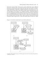
Figure 3.1 is a graphical representation of the problem space for reasoning about user
interface plasticity. The plastic UI snowflake can be used to characterize existing tools or
to express requirements for future tools. Each branch of the snowflake presents a number
of issues relevant to UI plasticity. These include: the classes of targets that the tool
supports (adaptation to platforms, environments and users), the stages of the development
process that the tool covers (design, implementation or run-time), the actors that perform
the adaptation of the user interface to the target (human or system intervention) and
the dynamism of user interfaces that the tools are able to produce (static pre-computed
or dynamic on-fly computed user interfaces). When considering adaptation to multiple
platforms, we also need to discuss the way the user interface is migrated across platforms.
In the following sub-sections, we present each dimension of the snowflake in detail,
illustrated with state-of-the-art examples. In particular, we develop multi-platform target-
ing. Although multi-user targeting is just as important, we are not yet in a position to
provide a sound analysis for it. For adaptation to multi-environment targeting, please refer
to [Moran and Dourish 2001] and [Coutaz and Rey 2002].
A REFERENCE FRAMEWORK FOR THE DEVELOPMENT OF PLASTIC USER INTERFACES 33
Design
Run-time support
Forward engineering
Reverse engineering
Toolbox
Infrastructure
Java
HTML
Flash
Environment
Platform
U
ser
Physical presentation
Logical presentation
Dialogue controller
Functional core adapter
At run-time
Betwen
sessions
Pre-computed
UI
On-the-fly
computed UI
Human
Human
System
System
UI software
components
Target
UI migration
UI computation
Development
phases
UI implementa-
tion
Actor
(run-time)
Actor
(design)
Figure 3.1. The Plastic UI Snowflake: a problem space for characterizing software tools, and for
expressing requirements for software tools aimed at plastic user interfaces.
3.3.1. TARGET SENSITIVITY
In software tools for plasticity, the first issue to consider is the kind of targets a partic-
ular tool addresses or is supposed to address. Are we concerned with multi-platform or
multi-environment only? Do we need adaptation to multiple classes of users? Or is it a
combination of platforms, environments and users?
For example, ARTStudio [Thevenin 2001] addresses the problem of multi-platform
targeting whereas the Context Toolkit [Dey et al. 2001] is concerned with environment
sensitivity only. AVANTI, which can support visually impaired users, addresses adaptation
to end-users [Stephanidis et al. 2001]. There is currently no tool (or combination of tools)
that supports all three dimensions of plasticity, i.e. users, platforms and environments.
3.3.2. CLASSES OF SOFTWARE TOOLS
As with any software tool, we must distinguish between tools that support the design
phases of a system versus implementation tools and mechanisms used at run-time.
34 DAVID THEVENIN, JO
¨
ELLE COUTAZ, AND GA
¨
ELLE CALVARY
Design phases are primarily concerned with forward engineering and reverse engi-
neering of legacy systems. Forward engineering is supported by specification tools for
modelling, for configuration management and versioning, as well as for code generation:
• Modelling is a fundamental activity in system design. In HCI, model-based tools such as
Humanoid [Szekely 1996], ADEPT [Johnson et al. 1993] and TRIDENT [Vanderdonckt
1995] have shown significant promise, not only as conceptualization tools, but also as
generators. If these approaches have failed in the past because of their high learning
curve [Myers et al. 2000], they are being reconsidered for multi-target generation as in
MOBI-D [Eisenstein et al. 2001] and USE-IT [Akoumianakis and Stephanidis 1997].
• Configuration management and versioning have been initiated with the emergence of
large-scale software. They apply equally to multi-targeting and plasticity for two rea-
sons. First, the code that supports a particular target can be derived from the high-level
specification of a configuration. Secondly, the iterative nature of user interface develop-
ment calls for versioning support. In particular, consistency must be maintained between
the configurations that support a particular target.
• Generation has long been viewed as a reification process from high-level abstract
description to executable code. For the purpose of multi-targeting and plasticity, we
suggest generation by reification, as well as by translation where transformations are
applied to descriptions while preserving their level of abstraction. The Process Ref-
erence framework described in Section 3.4 shows how to combine reification and
translation.
• Tools for reverse engineering, that is eliciting software architecture from source code,
are recent. In Section 3.4, we will see how tools such as Vaquita [Bouillon et al. 2002]
can support the process of abstracting in order to plastify existing user interfaces.
Implementation phases are concerned with coding. Implementation may rely on infras-
tructure frameworks and toolkits. Infrastructure frameworks, such as the Internet or the
X window protocol, provide implementers with a basic reusable structure that acts as a
foundation for other system components such as toolkits. BEACH is an infrastructure that
supports any number of display screens each connected to a PC [Tandler 2001]. MID is
an infrastructure that extends Windows to support any number of mice to control a single
display [Hourcade and Bederson 1999]. We are currently developing I-AM (Interaction
Abstract Machine), an infrastructure aimed at supporting any number of displays and input
devices, which from the programmer’s perspective will offer a uniform and dynamic inter-
action space [Coutaz et al. 2002]. Similar requirements motivate the blackboard-based
architecture developed for iRoom [Winograd 2001]. The Context Toolkit is a toolkit for
developing user interfaces that are sensitive to the environment [Dey et al. 2001].
3.3.3. ACTORS IN CHARGE OF ADAPTATION
The actors in charge of adaptation depend on the phase of the development process:
• At the design stage, multi-targeting and plasticising can be performed explicitly by
humans such as system designers and implementers, or it can rely on dedicated tools.
A REFERENCE FRAMEWORK FOR THE DEVELOPMENT OF PLASTIC USER INTERFACES 35
• At run-time, the user interface is adaptable or adaptive. It is adaptable when it adapts
at the user’s request, typically by providing preference menus. It is adaptive when
the user interface adapts on its own initiative. The right balance between adaptability
and adaptivity is a tricky problem. For example, in context-aware computing, Cheverst
et al. [2001] report that using location and time to simplify users’ tasks sometimes
makes users feel that they are being pre-empted by the system. Similarly, adaptivity to
users has been widely attempted with limited success [Browne et al. 1990].
3.3.4. COMPUTATION OF MULTI-TARGET AND PLASTIC USER INTERFACES
The phases that designers and developers elicit for multi-targeting and plasticity have a
direct impact on the types of user interfaces produced for the run-time phase. Multi-target
and plastic user interfaces may be pre-computed, or they may be computed on the fly:
• Pre-computed user interfaces result from adaptation performed during the design or
implementation phases of the development process: given a functional core (i.e., an
application), a specific user interface is generated for every envisioned target.
• Dynamic multi-target and plastic user interfaces are computed on the fly based on run-
time mechanisms. Examples of run-time mechanisms include the Multimodal Toolkit
[Crease et al. 2000], which supports dynamic adaptation to interactive devices. Flex-
Clock [Grolaux 2000], which dynamically adapts to window sizes, is another example.
• The generated user interface can be a combination of static pre-computed components
with on-the-fly adaptation. In this case, we have a hybrid multi-target plastic user
interface. As a general rule of thumb, pre-computation is used for the overall structure
of the user interface to ensure that the system runs quickly. However since this approach
does not always provide an ideal adaptation to the situation, dynamic computation is
added for fine-grain adjustments.
3.3.5. USER INTERFACE SOFTWARE COMPONENTS
A number of software components are affected when adapting an interface for multi-
targeting and plasticity. There is a large body of literature on this issue. However, because
the software perspective is often mixed with the user’s perception of adaptation, the state
of the art does not provide a clear, unambiguous picture. For example, Dieterich et al.
introduce five levels of adaptation: the lexical, syntactic, semantic, task and goal levels
[Dieterich et al. 1993]. More recently, Stephanidis et al. define the lexical, syntactic and
semantic levels of adaptation using examples [Stephanidis and Savidis 2001]. We propose
to use Arch [Bass et al. 1992], a reference software architecture model, as a sound basis
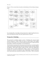
for characterizing software adaptation to target changes.
As shown in Figure 3.2, the Functional Core (FC) covers the domain-dependent con-
cepts and functions. At the other extreme is the Physical Presentation Component (PPC),
which is dependent on the toolkit used for implementing the look and feel of the inter-
active system. The PPC is in charge of presenting the domain concepts and functions in
terms of physical interactive objects (also known as widgets or interactors). The keystone
of the arch structure is the Dialog Control (DC) whose role consists of regulating task
sequencing. For example, the Dialog Control ensures that the user executes the task open
36 DAVID THEVENIN, JO
¨
ELLE COUTAZ, AND GA
¨
ELLE CALVARY
Select Modify
Visualize
Workstation detail
editing
Visualize
PDA detail
Editing
FC
FCA
Dialog
control
Logical
pres.
Physical
pres.
On macOS-X
(NSbutton)
On java/JFC
(Jbutton)
On palm
(button)
Same interactor, different presentations
Navigation using "Tabbed Pane"
Navigation using "Link"
Navigation adaptation:
Presentation adaptation:
Month:
Month:
Label + combobox:
Label + textfield:
Same functional capacity,
different interactors
Functionalities proposed by the system
Views on the
functional core
Workstation detail
- attr 1
- attr 2
- attr 3
- attr 4
PDA detail
- attr 1' = fc (attr1)
- attr 2
Figure 3.2. Arch architecture model.
document before performing any editing task. The FC, DC and PPC do not exchange data
directly. Instead, they mediate through adaptors: the Functional Core Adaptor (FCA) and
the Logical Presentation Component (LPC). The FCA is intended to accommodate vari-
ous forms of mismatch between the Functional Core and the user interface. The Logical
Presentation Component insulates the rendering of domain objects from the interaction
toolkit of the target platform.
Using Arch as a structuring framework, the software components affected by multi-
targeting and plasticity are the FCA, the DC, the LPC, the PPC, or a combination of
them. In particular:
• At the Physical Presentation Component level, physical interactor classes used for
implementing the user interface are kept unchanged but their rendering and behaviour
may change across platforms. For example, if a concept is rendered as a button class,
this concept will be represented as a button regardless of the target platform. However,
the look and feel of the button may vary. This type of adaptation is used in the Tk
graphical user interface toolkit as well as in Java/AWT with the notion of peers.
• At the Logical Presentation Component level, adaptation consists of changing the rep-
resentation of the domain concepts. For example, the concept of month can be rendered
as a Label +TextField, or as a Label + ComboBox, or as a dedicated physical interac-
tor. In an LPC adaptation, physical interactors may change across platforms provided
that their representational and interactional capabilities are equivalent. The implemen-
tation of an LPC level adaptation can usefully rely on the distinction between abstract
A REFERENCE FRAMEWORK FOR THE DEVELOPMENT OF PLASTIC USER INTERFACES 37
interactive objects and concrete interactive objects as presented in [Vanderdonckt and
Bodard 1993].
• At the Dialogue Control level, the tasks that can be executed with the system are kept
unchanged but their organization is modified. As a result, the structure of the dialogue
is changed. AVANTI’s polymorphic tasks [Stephanidis et al. 2001] are an example of
a DC level adaptation.
• At the Functional Core Adaptor level, the nature of the entities as well as the functions
exported by the functional core are changed. Zizi’s semantic zoom is an example of
an FCA level adaptation [Zizi and Beaudouin-Lafon 1994].
As illustrated by the above examples, Arch offers a clear analysis of the impact of a
particular adaptation on the software components of a user interface.
3.3.6. USER INTERFACE MIGRATION
User interface migration corresponds to the transfer of the user interface between different
platforms. It may be possible either at run-time or only between sessions:
• On-fly migration requires that the state of the functional core be saved as well as that
of the user interface. The state of the user interface can be saved at multiple levels
of granularity: when saved at the Dialogue Control level, the user can pursue the task
from the beginning of the current task; when saved at the Logical Presentation or at the
Physical Presentation levels, the user is able to carry on the current task at the exact
point where they left off, and there is no discontinuity.
• When migration is possible only between sessions, the user has to quit the application,
and then restart the application from the saved state of the functional core. In this case,
the interaction process is interrupted. More research is required to determine how to
minimize this disruption.
User interface migration between platforms places a high demand on the underly-
ing infrastructure and toolkits. It also raises interesting user-centred design issues that
should be addressed within the design process. Design phases are addressed next with the
presentation of the Process Reference Framework.
3.4. THE PROCESS REFERENCE FRAMEWORK
FOR MULTI-TARGET AND PLASTIC UIs
The Process Reference Framework provides designers and developers with generic princi-
ples for structuring and understanding the development process of multi-target and plastic
user interfaces. We present an overall description of the framework in Section 3.4.1 fol-
lowed by a more detailed expression of the framework applied to the design stage in
Section 3.4.2. Different instantiations of the framework are presented in Section 3.4.3.
Run-time architecture, which can be found in [Crease et al. 2000] and [Calvary et al.
2001b], is not discussed in this chapter.
38 DAVID THEVENIN, JO
¨
ELLE COUTAZ, AND GA
¨
ELLE CALVARY
3.4.1. GENERAL DESCRIPTION
As shown in Figure 3.3, the framework stresses a model-based approach coupled with a
software development lifecycle.
3.4.1.1. Models and Lifecycle
Model-based approaches, which rely on high-level specifications, provide the foundations
for code generation and code abstraction. This process of code generation and code
abstraction reduces the cost of code production and code reusability while improving
code quality.
The Process Reference Framework uses three types of models, where each type cor-
responds to a step of the lifecycle:
• Ontological models are meta-models that define the key dimensions of plasticity. They
are independent from any domain and interactive system but are conveyed in the tools
used for developing multi-target and plastic user interfaces. They are useful for the
tool developer. When instantiated with tool support, ontological models give rise to
archetypal models.
• Archetypal models depend on the domain and the interactive system being developed.
They serve as input specifications for the design phase of an interactive system.
• Observed models are executable models that support the adaptation process at run-time.
Concepts
Target 1
Final user
interface
Abstract
interface
Run-time infrastructure
Ontological
models
Domain
Concepts
Tasks
Context of use
User
Platform
Environment
Adaptation
Evolution
Transition
Archetypal models
Target 2
Tasks
User
Platform
Environment
Evolution
Transition
Observed
models
Translation
Forward engineering:
reification
Human
intervention
Design
phase
Run-time
phase
Concepts and
task model
Concrete
interface
Reverse
engineering
Figure 3.3. Process Reference Framework for the development of plastic user interfaces.
A REFERENCE FRAMEWORK FOR THE DEVELOPMENT OF PLASTIC USER INTERFACES 39
As shown in Figure 3.3, the design phase complies with a structured development process
whose end result is a set of executable user interfaces (Final User Interfaces) each aimed
at a particular archetypal target.
3.4.1.2. Coverage of the Models
As shown in Figure 3.3, the Process Reference Framework uses the following classes:
• Domain models cover the domain concepts and user tasks. Domain concepts denote the
entities that users manipulate in their tasks. Tasks refer to the activities users undertake
in order to attain their goals with the system.
• Context of use models describe a target in terms of user, platform and environment.
• Adaptation models specify how to adapt the system when the context of use and/or
the target change. They include rules for selecting interactors, building user interface
dialogues, etc.
These three classes of models (i.e., domain, context of use and adaptation models) may
be ontological, archetypal or observed. As an illustration, in ARTStudio, the ontological
task model is similar to the ConcurTaskTree concept [Breedvelt-Schouten et al. 1997],
but is enhanced with decorations that specify the target audience. When instantiated as
an archetypal task model, the ontological model can indicate that a given task does not
make sense with a specific device and context, for example on a PDA in a train.
Having introduced the principles of the Process Reference Framework, we now present
the framework as it is used in the design phase of multi-target and plastic user interfaces.
3.4.2. THE PROCESS REFERENCE FRAMEWORK IN THE DESIGN PHASE
In the design phase, the Process Reference Framework provides designers and develop-
ers with generic principles for structuring and understanding the development process of
multi-target and plastic user interfaces. The design phase employs domain, context of
use and adaptation models that are instantiations of the same models in the ontological
domain. Archetypal models are referenced as well in the development process. As shown
in Figure 3.3, the process is a combination of vertical reification and horizontal trans-
lation. Vertical reification is applied for a particular target while translation is used to
create bridges between the descriptions for different targets. Reification and translation
are discussed next.
3.4.2.1. Reification and Translation
Reification covers the inference process from high-level abstract descriptions to run-
time code. As shown in Figure 3.3, the framework uses a four-step reification process: a
Concept and Task Model is reified into an Abstract User Interface which, in turn, leads
to a Concrete User Interface. The Concrete User Interface is then turned into a Final
User Interface.
At the highest level, the Concept and Task Model brings together the concepts and
task descriptions produced by the designers for that particular interactive system and that
particular target.
40 DAVID THEVENIN, JO
¨
ELLE COUTAZ, AND GA
¨
ELLE CALVARY
An Abstract User Interface (Abstract UI) is a canonical expression of the rendering
of the domain concepts and functions in a way that is independent of the interactors
available for the target. For example, in ARTStudio, an Abstract UI is a collection of
related workspaces. The relations between the workspaces are inferred from (i) the task
relationships expressed in the Concept and Task model and (ii) the structure of the con-
cepts described in the Concept model. Similarly, connectedness between concepts and
tasks is inferred from the Concept and Task model. The canonical structure of navigation
within the user interface is defined in this model as access links between workspaces.
A Concrete User Interface (Concrete UI) turns an Abstract UI into an interactor-
dependent expression. Although a Concrete UI makes explicit the final look and feel
of the Final User Interface, it is still a mock-up that runs only within the development
environment.
A Final User Interface (Final UI), generated from a Concrete UI, is expressed in source
code, such as Java and HTML. It can then be interpreted or compiled as a pre-computed
user interface and plugged into a run-time infrastructure that supports dynamic adaptation
to multiple targets.
A translation is an operation that transforms a description intended for a particular
target into a description of the same class but aimed at a different target. As shown in
Figure 3.3, translation can be applied between tasks and concepts for different targets,
and/or between Abstract UIs, and/or Concrete UIs, and/or Final UIs.
Although high-level specifications are powerful tools, they have a cost. As observed
by Myers et al. concerning the problem of ‘threshold and ceiling effects’ [Myers et al.
2000], powerful tools require steep learning curves. Conversely, tools that are easy to
master do not necessarily provide the required support. Human intervention, decoration
and factorisation, discussed next, can solve this dual problem.
3.4.2.2. Human Intervention
In the absence of tool support, reification and translation are performed manually by
human experts. At the other extreme, tools can perform them automatically. However,
full automation has a price: either the tool produces common-denominator solutions (e.g.,
standard WIMP UIs produced by model-based UI generators) or the designer has to
specify an overwhelming number of details to get the desired results.
As shown in Figure 3.3, the Process Reference Framework addresses cooperation
between human and tool as follows: the development environment infers descriptions
that the designer can then adjust to specific requirements. For example, in ARTStudio,
the designer can modify the relationships between workspaces, can change the layouts of
the interactors, or even replace interactors. Decorations, presented next, provide another
way to perform adjustments.
3.4.2.3. Decorations
A decoration is a type of information attached to description elements. Although a dec-
oration does not modify the description per se, it provides information that modifies the
interpretation of the description.