Software Fault Tolerance Techniques and Implementation phần 2 pot
Bạn đang xem bản rút gọn của tài liệu. Xem và tải ngay bản đầy đủ của tài liệu tại đây (971.08 KB, 35 trang )
hardware fault tolerance. Examples of this type of information redundancy
include error-detecting and error-correcting codes.
Diverse data (not simple redundant copies) can be used for tolerat-
ing software faults. A data re-expression algorithm (DRA) produces differ-
ent representations of a modules input data. This transformed data is input
to copies of the module in data diverse software fault tolerance techniques.
Data diversity is presented in more detail in the following chapter. Tech-
niques that utilize diverse data are described in Chapter 5.
1.5.3 Temporal Redundancy
Temporal redundancy involves the use of additional time to perform tasks
related to fault tolerance. It is used for both hardware and software fault tol-
erance. Temporal redundancy commonly comprises repeating an execution
using the same software and hardware resources involved in the initial, failed
execution. This is typical of hardware backward recovery (roll-back) schemes.
Backward recovery schemes used to recover from software faults typically use
a combination of temporal and software redundancy.
Timing or transient faults arise from the often complex interaction of
hardware, software, and the operating system. These failures, which are diffi-
cult to duplicate and diagnose, are called Heisenbugs [36]. Simple replica-
tion of redundant software or of the same software can overcome transient
faults because prior to the reexecution time, the temporary circumstances
causing the fault are then usually absent. If the conditions causing the fault
persist at the time of reexecution, the reexecution will again result in failure.
Temporal redundancy has a great advantage for some applications
it does not require redundant hardware or software. It simply requires the
availability of additional time to reexecute the failed process. Temporal
redundancy can then be used in applications in which time is readily avail-
able, such as many human-interactive programs. Applications with hard
real-time constraints, however, are not likely candidates for using temporal
redundancy. The additional time used for reexecution may cause missed
deadlines. Forward recovery techniques using software redundancy are more
appropriate for these applications.
1.6 Summary
The need for dependable systems of all types and especially those con-
trolled by software was posed and illustrated by example. We humans, being
imperfect creatures, create imperfect software. These imperfections cannot
Introduction
presently be tested or proven away, and it would be far too risky to simply
ignore them. So, we will examine means to tolerate the effects of the imper-
fections during system operation until the problem disappears or is han-
dled in another manner and brought to conclusion (for example, by system
shutdown and repair). To give a basis for the software fault tolerance tech-
nique discussion, we provide definitions of several basic termsfault, error,
failure, and software fault tolerance. The basic organization of the book and a
proposed reading guide were presented, illustrating both basic and advanced
tours of the techniques.
To achieve dependable systems, it is necessary to use a combination of
techniques from four risk mitigation areas: fault avoidance, fault removal,
fault forecasting, and fault tolerance. Unfortunately, there is no single com-
bination of these techniques that is significantly better in all situations. The
conventional wisdom that system and software requirements should be
addressed early and thoroughly becomes more apparent as it is seen that later
efforts at risk mitigation cannot determine or compensate for requirements
specification errors. However, the effective use of risk mitigation techniques
does increase system dependability. In each case, one must creatively com-
bine techniques from each of the four areas to best address system constraints
in terms of cost, complexity, and effectiveness.
We have seen that neither forward nor backward recovery is ideal.
Their advantages and disadvantages were identified in this chapter. These
recovery techniques do not have to be used in exclusion of each other. For
instance, one can try forward recovery after using backward recovery if the
error persists [20].
Most, if not all, software fault tolerance techniques are based on some
type of redundancysoftware, information, and/or time. The selection of
which type of redundancy to use is dependent on the applications require-
ments, its available resources, and the available techniques. The detection
and tolerance of software faults usually require diversity (except in the case of
temporal redundancy used against transient faults).
Software fault tolerance is not a panacea for all our software problems.
Since, at least for the near future, software fault tolerance will primarily be
used in critical (for one reason or another) systems, it is even more important
to emphasize that fault tolerant does not mean safe, nor does it cover the
other attributes comprising dependability (as none of these covers fault toler-
ance). Each must be designed-in and their, at times conflicting, character-
istics analyzed. Poor requirements analysis will yield poor software in most
cases. Simply applying a software fault tolerance technique prior to testing or
fielding a system is not sufficient. Software due diligence is required!
22 Software Fault Tolerance Techniques and Implementation
References
[1] Neumann, P. G., Computer Related Risks, Reading, MA: Addison-Wesley, 1995.
[2] Leveson, N. G., SAFEWARE: System Safety and Computers, Reading, MA: Addison-
Wesley, 1995.
[3] Herrmann, D. S., Software Safety and Reliability: Techniques, Approaches, and Stan-
dards of Key Industrial Sectors, Los Alamitos, CA: IEEE Computer Society, 1999.
[4] ACM SIGSOFT, RISKS Section, Software Engineering Notes, Vol. 15, No. 2, 1990.
[5] Mission Control Saves Inselat Rescue from Software Checklist Problems, Aviation
Week and Space Technology, May 25, 1992, p. 79.
[6] Asker, J. R., Space Station Designers Intensify Effort to Counter Orbital Debris,
Aviation Week and Space Technology, June 8, 1992, pp. 6869.
[7] ACM SIGSOFT, RISKS Section, Software Engineering Notes, Vol. 17, No. 3, 1992.
[8] ACM SIGSOFT, RISKS Section, Software Engineering Notes, Vol. 9, No. 5, 1984.
[9] Software Glitch Cripples AT&T, Telephony, January 22, 1990, pp. 1011.
[10] ACM SIGSOFT, RISKS Section, Software Engineering Notes, Vol. 18, No. 1, 1993.
[11] ACM SIGSOFT, RISKS Section, Software Engineering Notes, Vol. 18, No. 25, 1993.
[12] Denning, P. J. (ed.), Computers Under Attack: Intruders, Worms, and Viruses, New
York: ACM Press, and Reading, MA: Addison-Wesley, 1990.
[13] DeTreville, J., A Cautionary Tale, Software Engineering Notes, Vol. 16, No. 2, 1991,
pp. 1922.
[14] ACM SIGSOFT, RISKS Section, Software Engineering Notes, Vol. 15, No. 2, 1990.
[15] ACM SIGSOFT, RISKS Section, Software Engineering Notes, Vol. 15, No. 3, 1990.
[16] ACM SIGSOFT, RISKS Section, Software Engineering Notes, Vol. 15, No. 5, 1990.
[17] Leveson, N. G., and C. Turner, An Investigation of the Therac-25 Accidents, IEEE
Computer, 1993, pp. 1841.
[18] Neumann, P. G., et al., A Provably Secure Operating System: The System, Its Applica-
tions, and Proofs, (2nd ed.) SRI International Computer Science Lab, Technical
Report CSL-116, Menlo Park, CA, 1980.
[19] Eklund, B., Down and Out: Distributed Computing Has Made Failure Even More
Dangerous, Red Herring, Dec. 18, 2000, pp. 186188.
[20] Laprie, J. -C., Computing Systems Dependability and Fault Tolerance: Basic Con-
cepts and Terminology, Fault Tolerant Considerations and Methods for Guidance and
Control Systems, NATO Advisory Group for Aerospace Research and Development,
AGARDograph No. 289, M. J. Pelegrin (ed.), Toulouse Cedex, France, 1987.
Introduction !
[21] Laprie, J. -C., DependabilityIts Attributes, Impairments and Means, in B. Ran-
dell, et al. (eds.), Predictably Dependable Computing Systems, New York: Springer,
1995, pp. 324.
[22] Randell, B., System Structure for Software Fault Tolerance, IEEE Transactions on
Software Engineering, Vol. SE-1, No. 2, 1975, pp. 220232.
[23] Avizienis, A., On the Implementation of N-Version Programming for Software
Fault-Tolerance During Execution, COMPSAC 77, 1977, pp. 149155.
[24] Laprie, J. -C., Dependable Computing: Concepts, Limits, Challenges, Proceedings of
FTCS-25, Pasadena, 1995, pp. 4254.
[25] Lyu, M. R. (ed.), Handbook of Software Reliability Engineering, New York: IEEE Com-
puter Society Press, McGraw-Hill, 1996.
[26] Pullum, L. L., and S. A. Doyle, Tutorial: Software Testing, Annual Reliability and
Maintainability Symposium, Los Angeles, CA, 1998.
[27] Myers, G. J., Software Reliability, Principles and Practices, New York: John Wiley and
Sons, 1976.
[28] Fagan, M. E., Design and Code Inspections to Reduce Errors in Program Develop-
ment, IBM Systems Journal, Vol. 15, No. 3, 1976, pp. 219248.
[29] Grady, R. B., Practical Software Metrics for Project Management and Process Improve-
ment, Englewood Cliffs, NJ: Prentice-Hall, 1992.
[30] Jalote, P., Fault Tolerance in Distributed Systems, Englewood Cliffs, NJ: Prentice Hall,
1994.
[31] Randell, B., and J. Xu, The Evolution of the Recovery Block Concept, in M. R. Lyu
(ed.), Software Fault Tolerance, New York: John Wiley and Sons, 1995, pp. 121.
[32] Mili, A., An Introduction to Program Fault Tolerance: A Structured Programming
Approach, New York: Prentice Hall, 1990.
[33] Xu, J., and B. Randell, Object-Oriented Construction of Fault-Tolerant Software,
University of Newcastle upon Tyne, Technical Report Series, No. 444, 1993.
[34] Levi, S. -T., and A. K. Agrawala, Fault Tolerant System Design, New York: McGraw-
Hill, 1994.
[35] Avizienis, A., The N-Version Approach to Fault-Tolerant Software, IEEE Transac-
tions on Software Engineering, Vol. SE-11, No. 12, 1985, pp. 14911501.
[36] Gray, J., A Census of Tandem System Availability Between 1985 and 1990, IEEE
Transactions on Reliability, Vol. 39, No. 4, 1990, pp. 409418.
24 Software Fault Tolerance Techniques and Implementation
2
Structuring Redundancy for Software
Fault Tolerance
In the previous chapter, we reviewed several types of redundancy often used
in fault tolerant systems. It was noted then that redundancy alone is not suf-
ficient for tolerance of software design faultssome form of diversity must
accompany the redundancy. Diversity can be applied at several different
levels in dependable systems. In fact, some regulatory agencies require the
implementation of diversity in the systems over which they preside, in par-
ticular the nuclear regulatory agencies.
For instance, the U.S. Nuclear Regulatory Agency, in its Digital
Instrumentation and Control Systems in Advanced Plants [1] states that
1. The applicant shall assess the defense-in-depth and diversity of
the proposed instrumentation and control system to demonstrate
that vulnerabilities to common-mode failures have been adequately
addressed. The staff considers software design errors to be credible
common-mode failures that must be specifically included in the
evaluation.
2. In performing the assessment, the vendor or applicant shall analyze
each postulated common-mode failure for each event that is evalu-
ated in the analysis section of the safety analysis report (SAR) using
best-estimate methods. The vendor or applicant shall demonstrate
adequate diversity within the design for each of these events.
#
The digital instrumentation and control systems of which they speak are
used to detect failures so that failed subsystems can be isolated and shut
down. These protection systems typically use a two-out-of-four voting
scheme that reverts to a two-out-of-three voter if one of the channels fails.
The failed channel is taken out of service, but the overall service continues
with the remaining channels.
The Canadian Atomic Energy Control (AECB) takes a similar stance
in Software in Protection and Control Systems [2], as stated below:
To achieve the required levels of safety and reliability, the system may
need to be designed to use multiple, diverse components performing
the same or similar functions. For example, AECB Reg. Docs. R-8 and
R-10 require 2 independent and diverse protective shutdown systems
in Canadian nuclear power reactors. The design should address this
danger by enforcing other types of diversity [other than design diversity]
such as functional diversity, independent and diverse sensors, and tim-
ing diversity.
In aviation, the regulatory situation differs, but the use of diversity is
fairly common. In terms of regulation, the U.S. Federal Aviation Admin-
istration states in [3] that since the degree of protection afforded by design
diversity is not quantifiable, employing diversity will only be counted as an
additional protection beyond the already required levels of assurance.
To illustrate the use of diversity in an aviation system, look at Airbus,
in which diversity is employed at several levels. Diverse software is used in
the Airbus A-310, A-320, A-330, and A-340 flight control systems [4, 5].
The A-320 flight control system uses two types of computers that are manu-
factured by different companies, resulting in different architectures and
microprocessors. The computers are based on different functional specifi-
cations. One of four diverse software packages resides on each control and
monitoring channel on the two computers. The controller uses N-version
programming (NVP) to manage the diverse software, enabling software fault
tolerance.
This chapter will illustrate how redundancy is structured for software
fault tolerance. We will start by taking a step back to examine robust soft-
waresoftware that does not use redundancy to implement fault tolerance.
The majority of the chapter will examine design diversity, including issues
surrounding its use and cost, case studies examining its effectiveness, levels
of diversity application, and factors that influence diversity. Next, we will
examine two additional means of introducing diversity for fault tolerance
26 Software Fault Tolerance Techniques and Implementation
TEAMFLY
Team-Fly
®
purposesdata and temporal diversity. To assist in developing and evaluat-
ing software fault tolerance techniques, several researchers and practitioners
have described hardware/software architectures underlying the techniques
and design/implementation components with which to build the techniques.
We will provide these results to assist the reader in developing and evaluating
his or her own implementations of the techniques.
2.1 Robust Software
Although most of the techniques and approaches to software fault tolerance
use some form of redundancy, the robust software approach does not. The
software property robustness is defined as the extent to which software can
continue to operate correctly despite the introduction of invalid inputs [6].
The invalid inputs are defined in the program specification. The definition
of robustness could be taken literally and include all software fault tolerance
techniques. However, as it is used here, robust software will include only
nonredundant software that, at a minimum, properly handles the following:
• Out of range inputs;
•
Inputs of the wrong type;
• Inputs in the wrong format.
It must handle these without degradation of those functions not dependent
on the invalid input(s).
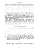
As shown in Figure 2.1, when invalid inputs are detected, several
optional courses of action may be taken by the robust software. These
include:
•
Requesting a new input (to the input source, in this case, most likely
a human operator);
•
Using the last acceptable value for the input variable(s) in question;
•
Using a predefined default value for the input.
After detection and initial tolerance of the invalid input, the robust software
raises an exception flag indicating the need for another program element to
handle the exception condition.
Structuring Redundancy for Software Fault Tolerance %
Examination of self-checking software [7] features reveal that it can
reside under the definition of robust software. Those features are:
•
Testing the input data by, for example, error detecting code and
data type checks;
•
Testing the control sequences by, for example, setting bounds on
loop iterations;
•
Testing the function of the process by, for example, performing a
reasonableness check on the output.
28 Software Fault Tolerance Techniques and Implementation
Inputs
Raise
exception
flag
Request
new input
Use last
acceptable
value
Use predefined
default value
or
Valid
Input
?
or
Continue
software
operation
Handle
exceptions
Robus
t software
T
rue
False
Result
Figu re 2.1 Robu st software operation.
An advantage of robust software is that, since it provides protection
against predefined, input-related problems, these errors are typically detected
early in the development and test process. A disadvantage of using robust
software is that, since its checks are specific to input-related faults as defined
in the specification, it usually cannot detect and tolerate any other less spe-
cific faults. Hence, the need exists for other means to tolerate such faults,
mainly through the use of design, data, or temporal diversity.
2.2 Design Diversity
Design diversity [8] is the provision of identical services through separate
design and implementations [911]. As noted earlier, redundant, exact cop-
ies of software components alone cannot increase reliability in the face of
software design faults. One solution is to provide diversity in the design and
implementation of the software. These different components are alterna-
tively called modules, versions, variants, or alternatives. The goal of design
diversity is to make the modules as diverse and independent as possible, with
the ultimate objective being the minimization of identical error causes. We
want to increase the probability that when the software variants fail, they fail
on disjoint subsets of the input space. In addition, we want the reliability of
the variants as high as possible, so that at least one variant will be operational
at all times.
Design diversity begins with an initial requirements specification. The
specification states the functional requirements of the software, when the
decisions (adjudications) are to be made, and upon what data the decision-
making will be performed. Note that the specifications may also employ
diversity as long as the systems functional equivalency is maintained. (When
coupled with different inputs for each variant, the use of diverse specifica-
tions is termed functional diversity.) Each developer or development organi-
zation responsible for a variant implements the variant to the specification
and provides the outputs required by the specification.
Figure 2.2 illustrates the basic design diversity concept. Inputs (from
the same or diverse sources) are provided to the variants. The variants per-
form their operations using these inputs. Since there are multiple results, this
redundancy requires a means to decide which result to use. The variant out-
puts are examined by a decider or adjudicator. The adjudicator determines
which, if any, variant result is correct or acceptable to forward to the next
part of the software system. There are a number of adjudication algorithms
available. These are discussed in Chapter 7.
Structuring Redundancy for Software Fault Tolerance '
When significant independence in the variants failure profile can be
achieved, a simple and efficient adjudicator can be used, and design diversity
provides effective error recovery from design faults. It is likely, however, that
completely independent development cannot be achieved in practice [12].
Given the higher cost of design diversity, it has thus typically been used only
in ultrareliable systems (i.e., those with failure intensity objectives less than
10
−6
failure/CPU hour) [12].
A word about the cost of design diversity before we continue. It has
been often stated that design diversity is prohibitively costly. Studies have
shown, however, that the cost of an additional diverse variant does not dou-
ble the cost of the system [1316]. More recently, a study on industrial soft-
ware [17] showed that the cost of a design diverse variant is between 0.7 and
0.85 times the cost of a nondiverse software module. The reason for the less-
than-double cost is that even though some parts of the development process
are performed separately for each variant (namely detailed design, coding,
and unit and integration testing), others are performed for the software
system as a whole (specifications, high-level design, and system tests). Note
that the systemwide processes can limit the amount of diversity possible. In
addition, the process of developing diverse software can take advantage of
the existence of more than one variant, specifically, through back-to-back
testing.
The remainder of this discussion on design diversity presents the results
of case studies and experiments in design diversity, the layers or levels at
which design diversity can be applied, and the factors that influence
diversity.
30 Software Fault Tolerance Techniques and Implementation
Input
Variant 1
Variant 2 Variant n
. . .
Decider
Correct
Incorrect
. . .
Figu re 2.2 Basi c design d ivers ity.
2.2.1 Case Studies and Experiments in Design Diversity
There have been numerous experiments and case studies on design diversity,
mainly on the NVP technique that employs design diversity. Bishop [18]
presents a useful review of the research in this area. The focus of most of
the research centers around the factors affecting the diversity of the faults
encountered, the reliability improvement using NVP, and investigation
of the independence assumption. (The independence assumption states that
the failures of diverse versions will be independent and thus detectable.)
Table 2.1 summarizes some typical experiments.
The summarized findings of the experiments are provided below [18].
•
A significant proportion of the faults found in the experiments were
similar.
•
The major cause of the common faults was the specification.
[Attempts to avoid this include use of diverse specifications and the
N-version software process (see Section 3.3.3).]
• The major deficiencies in the specifications were incompleteness and
ambiguity. This caused the programmer to make sometimes incor-
rect and potentially common, design choices.
•
Diverse design specifications can potentially reduce specification-
related common faults.
Structuring Redundancy for Software Fault Tolerance !
Table 2.1
Summary of Some N-Version Programming Experime nts.
(From: [18], © 1995, John Wiley & Sons, Ltd. Reproduce d with permiss ion.)
Experiment Specifications Languages Versions Reference
Halden, React or Trip 1 2 2 [19]
NASA, First Generation 3 1 18 [20]
KFK, Reactor Trip 1 3 3 [21]
NASA/RTI, Lau nch Interceptor 1 3 3 [22]
UCI/UVA, Laun ch Interceptor 1 1 27 [23]
Halden (PODS), Reactor Trip 2 2 3 [24]
UCLA, Flight Control 1 6 6 [25]
NASA (2nd Generation), Inertial
Guidance
1 1 20 [26]
UI/Rockwell, Flight Con trol 1 1 15 [27]
•
It was found that the use of relatively formal notations (see [20, 28])
was effective in reducing specification-related faults caused by
incompleteness and ambiguity. The use of diverse specifications
raises additional concerns, however, because the specifications may
not be equivalent. In practice, a single good requirements specifica-
tion is used unless it is shown that the diverse specifications are
mathematically equivalent.
•
In general, fewer faults seem to occur in strongly typed, tightly
structured languages such as Modula 2 and Ada, while low-level
assembler has the worst performance in terms of fault occurrence.
•
The protocol for communication between the development teams
and the project coordinator in the N-version design paradigm
[25, 27] is key to the success of the resulting software. Also key is
the presence of a good initial specification.
•
A significant improvement in the reduction of identical and very
similar faults was found by using the N-version design paradigm.
•
An experimental te st of the independe nce a ssumpti on [23, 29]
rejected the assumption to a high level of confidence. The depen-
dent failures were claimed to be due to design faults only, and not
due to faults in the specification. Analysis of the faults showed that
the programmers tended to make similar mistakes.
•
A theoretical analysis of coincident failures [26] showed that if mis-
takes were more likely for some specific input values, then depen-
dent failures would be observed.
•
Littlewood and Miller [30] refined the previous finding to show
that it was possible to have cases in which dependent failures
occurred less frequently than predicted by the independence
assumption. It is noted that the degree of difficulty distribution
is not the same for all programmers and if this distribution can be
altered using different development processes, then failures are likely
to occur in different regions of the input space, and hence the fail-
ures would not be correlated.
•
Masking of internal errors causes dependent failures to be observed
even if the internal error rates are independent. Any output variable
whose computation relies on masking functions (e.g., AND gates,
OR gates, MIN and MAX functions, and selection functions such
as IF/THEN/ELSE, case statements, and such) is likely to exhibit
some dependent failures in diverse implementations.
32 Software Fault Tolerance Techniques and Implementation
•
The reliability improvement in one study [27] showed an improve-
ment factor of 13 for an average triple (set of three variants), not
including the error correction capabilities of the voting system. With
the voting system included, the average reliability improvement is
increased to approximately 58.
Given these results, the main lesson to be gained from these experi-
ments is that the performance of N-version software (diverse software) is
severely limited if common faults are likely. The sources for these common
failures are most probably common implementation mistakes and omissions
and ambiguities in the requirements specification. Use of the N-version pro-
gramming paradigm has been helpful in minimizing these risks. In addition,
the use of metrics for identification of trouble spots in the program [31] may
be useful in focusing diversification efforts.
2.2.2 Levels of Diversity and Fault Tolerance Application
There are two aspects of the level of fault tolerance application to consider.
One is determining at what level of detail to decompose the system into
modules that will be diversified. The other involves the determination of
which layers of the system to diversify. To determine the level of decom-
position for diversification, we must examine the trade-offs between small-
and large-size components. Small components are generally less complex,
and their use leads to DMs, or adjudicators, that are easier to handle. Larger
components, however, are more favorable for effective diversity. Note also
that those places where a decision takes place (decision points) are nondiver-
sity points (and synchronization points for techniques such as NVP and
N-self-checking programming (NSCP)) and must be limited [32]. These
decision points are only required a priori for interaction with the environ-
ment in, for example, sensor data acquisition, delivery of orders to actuators,
and interactions with operators [32].
Diversity can be applied to several layers of the systemhardware,
application software, system software, operators, and the interfaces between
these components. When diversity is applied to more than one of these lay-
ers, it is generally termed multilayer diversity.
The use of diverse hardware architectures provides the benefits of hard-
ware diversityprotection of faults in the hardware manufacturing process
and subsequent physical faults. This diversity has been primarily used to tol-
erate hardware component failures and external physical faults.
Structuring Redundancy for Software Fault Tolerance !!
We have discussed the use of diversity at the application software level
(and will examine the specific fault tolerance techniques in a later chapter).
This is the most common form of diversity, typically used in safety-critical
systems to provide either a fail-halt property or to ensure continuity of
service. It has also been examined by several researchers (e.g., [33, 34], and
others) as a guard against malicious faults. Several multiversion systems using
both diverse hardware and software have been builtflight control comput-
ers for the Boeing 737-300 [35] and 7J7 [36]; the ATR.42, Airbus A-310,
A-320 [37], A-330, and A-340 aircraft; and the four-version MAFT sys-
tem [38].
Diversity at the operator-machine interface has been used to tolerate
both hardware and software design faults. Dual or triple displays of diverse
design and component technologies can be used by human operators in
many types of systems, including air traffic control, airliner cockpits, nuclear
power plant control rooms, and hospital intensive care facilities [39].
The major disadvantages of multilayer diversity are cost and speed. The
cost of designing and implementing diversity in multiple layers can be pro-
hibitive. In addition, the requirement to wait for the slowest component at
each diversified layer is a critical drawback for real-time systems.
One way to add diversity at a potentially lower cost is systematic
diversity, although it is typically used as a software technique for tolerating
hardware faults. Some examples of systematic diversity are [40]:
•
Utilization of different processor registers in the variants;
•
Transformation of mathematical expressions;
•
Different implementation of programming structures;
•
Different memory usage;
•
Using complementary branching conditions in the variants by trans-
forming the branch statements;
•
Different compilers and libraries;
•
Different optimization and code-generation options.
2.2.3 Factors Influencing Diversity
It is important to understand the factors that influence the diversity of soft-
ware so that resources may be put to use most effectively. The ultimate goal is
to determine those factors whose influence on software diversity most affect
a reduction in the likelihood of common mode failures. The collection of a
34 Software Fault Tolerance Techniques and Implementation
set of attributes that influence software diversity (in this case, the differences
between two pieces of software) was gathered by Burke and Wall [41].
A model was developed to represent the resulting software in terms of
both product and process attributes and the relationships between the attri-
butes. The attributes include both those that have the potential to enhance
and to inhibit diversity. For example, the software product attribute is decom-
posed into use and product profile attributes. These attributes are further bro-
ken down until leaf nodes such as number of loops and hazards containment
techniques are found. The software process attribute is decomposed into the
following subattributes: process profile, tools, personnel, and machines. Leaf
nodes on this major branch include the attributes skill level and assurance
of software tool. Some of these attributes may only be applicable to certain
applications.
Inputs to the model are provided for the leaf nodes only, such as skill
level, number of decision points, hardware dependencies, throughput, use of
recursion, standards compliance, consistency, and actual proof coverage, to name
a few. The resulting model output is a numerical measure indicating the
degree of belief that the two software versions under consideration are
diverse. Burke and Wall provide definitions for each of the attributes used
in the model [41]. Wall elsewhere [42] gives the rules used in the model.
Once a measure of diversity is known, it remains to be seen how that
diversity in fact influences the reduction of the likelihood of occurrence of
common-mode failures.
2.3 Data Diversity
Limitations of some design diverse techniques led to the development of data
diverse software fault tolerance techniques. The data diverse techniques are
meant to complement, rather than replace, design diverse techniques.
Ammann and Knight [4345] proposed data diversity as a software
fault tolerance strategy to complement design diversity. The employment of
data diversity involves obtaining a related set of points in the program data
space, executing the same software on those points, then using a decision
algorithm to determine the resulting output. Data diversity is based on a gen-
eralization of the works of Gray, Martin, and Morris [4648], which utilize
data diverse approaches relying on circumstantial changes in execution con-
ditions. These execution conditions can be changed deliberately to effect
data diversity [45]. This is done using data re-expression to obtain logi-
cally equivalent variants of the input data. Data diverse techniques use data
Structuring Redundancy for Software Fault Tolerance !#
re-expression algorithms (DRAs) to obtain their input data. Through a pilot
study on data diversity [4345], the N-copy programming (NCP) and retry
block (RtB) data diverse software fault tolerance structures were developed.
These techniques are discussed in Chapter 5.
The performance of data diverse software fault tolerance techniques
depends on the performance of the re-expression algorithm used. Ammann
and Knight [4345] suggest that there are several ways to perform data
re-expression and provide some insight on actual re-expression algorithms
and their use. DRAs are very application dependent. Development of a DRA
also requires a careful analysis of the type and magnitude of re-expression
appropriate for each data that is a candidate for re-expression [45]. There is
no general rule for the derivation of DRAs for all applications; however, this
can be done for some special cases [49]. It has also been shown that DRAs
exist for a fairly wide range of applications [50]. Of course, a simple DRA is
more desirable than a complex one because the simpler algorithm is less likely
to contain design faults.
A failure domain is the set of input points that cause program failure
[51]. The failure region is the geometry of the failure domain. It describes the
distributions of points in the failure domain and determines the effective-
ness of data diversity. The input space of most programs is a hyperspace
of many dimensions. For example, if a program reads and processes a set of
25 floating-point numbers, its input space has 25 dimensions. The valid
program space is defined by the specifications and by tested values and
ranges. Failure regions tend to be associated with transitions in the output
space [45].
The fault tolerance of a system employing data diversity depends upon
the ability of the DRA to produce data points that lie outside of a failure
region, given an initial data point within a failure region. The program exe-
cutes correctly on re-expressed data points only if they lie outside a failure
region. If the failure region has a small cross section in some dimensions,
then re-expression should have a high probability of translating the data
point out of the failure region. Many real-time control systems and other
applications can use DRAs. For example, sensors typically provide noisy and
imprecise data; hence small modifications to those data would not adversely
affect the application [43] and can yield a means of implementing fault toler-
ance. The performance of the DRA is much more important than the pro-
gram structure (e.g., NCP, RtB, and so on) in which it is embedded [52].
Not all applications can employ data diversity. Those that cannot do
so include applications in which an effective DRA cannot be found. This
may include: applications that do not primarily use numerical data (although
36 Software Fault Tolerance Techniques and Implementation
TEAMFLY
Team-Fly
®
character data re-expressions are possible), some that use primarily integer
data, some for which an exact re-expression algorithm is required (or where
approximation is not useful or that cannot afford or perform postexecution
adjustment), those for which a DRA that escapes the failure region cannot
be developed, and those for which the known re-expression algorithm(s) that
escape the failure region are resource-ineffective.
The remainder of this section provides an overview of data re-
expression, describes output sets and related types of data re-expression, and
illustrates examples of DRAs.
2.3.1 Overview of Data Re-Expression
Data re-expression is used to obtain alternate (or diverse) input data by gen-
erating logically equivalent input data sets. Given initial data within the
program failure region, the re-expressed input data should exist outside that
failure region. A re-expression algorithm, R, transforms the original input x
to produce the new input, y = R(x). The input y may either approximate x or
contain xs information in a different form. The program, P, and R deter-
mine the relationship between P(x) and P(y). Figure 2.3 illustrates basic data
re-expression. The requirements for the DRA can be derived from character-
istics of the outputs.
Other re-expression structures exist. Re-expression with postexecution
adjustment (Figure 2.4) allows the DRA to produce more diverse inputs than
those produced using the basic structure. A correction, A, is performed on
P(y) to undo the distortion produced by the re-expression algorithm, R.
If the distortion induced by R can be removed after execution, then this
approach allows major changes to the inputs and allows copies of the pro-
gram to operate in widely separated regions of the input space [45].
In another approach, data re-expression via decomposition and recom-
bination (Figure 2.5), an input x is decomposed into a related set of inputs
Structuring Redundancy for Software Fault Tolerance 37
x
Execute
P
Execute
P
Re-expression
y R x( )=
P y( )
P x( )
Figu re 2.3 Basi c da ta re-expression method. (Sourc e: [45], © 1988, IEE E. Reprinted with
perm issio n.) New data re-expression methods ma y be developed by varia-
tion on the ba sic method or by entirely new methods and algorithms.
and the program is then run on each of these related inputs. The results are
then recombined. Basic data re-expression and re-expression with postexecu-
tion adjustment allow for both exact and approximate DRAs (defined in the
following section).
2.3.2 Output Types and Related Data Re-Expression
Requirements for a DRA can be derived from characteristics of the outputs.
There exist three sets in the output space for a given input x (see Figures 2.6
and 2.7). The identical output set I contains all inputs y for which the correct
output is the same (up to numerical error) as the correct output, given x as
an input. Correct(in, out) is true if and only if (IFF), out is the output
required by the specifi- cation for input in. P
correct
represents a correctly imple-
mented specification. P
correct
(x) is the correct output for input x.
38 Software Fault Tolerance Techniques and Implementation
x
Adjust for
re-expression
Execute
P
Execute
P
Re-expression
y R x( )=
A P y( ( ))
P x( )
Figu re 2.4 Data re-expression with postexecution adjustment. (Source: [45], © 1988,
IEEE . Reprinted with permission.) Data re-expr essio n with postexecut ion
adju stmen t can prov ide even more diversity than basic data re-express ion.
x
Execute
P
.
.
.
x
.
.
.
P x( )
1
P x( )
P x( )
2
F P x( ( ))
i
P x( )
N
Recombine
P x( )
i
Decompose
, ,x x x→ …
1 N
Figu re 2.5 Data re-express ion via decomposition and recomb inati on. (Source : [45],
© 1988, IEEE. Reprinted with permission.) Data re-ex press ion via decomposi-
tion and recombination ca n also provide more diversity than bas ic data re-
expr essio n.
The valid output set V is the set of all inputs y for which a correct pro-
gram produces an acceptable output, given x as the actual input. Valid(in,
out) is true IFF out is a valid or acceptable output for input in. Hence, V is
the set of all inputs y for which a correct program produces an acceptable
output given x as the actual input.
The failure set F represents all inputs y for which the program fails to
produce a correct or acceptable output. Elements of F are, by definition, not
enumerated. However, the effectiveness of data diversity is determined by the
proportion of re-expressed points that lie in F.
Structuring Redundancy for Software Fault Tolerance 39
Identical output set
{ ( , ( ))}y Correct x P y|
correct
Valid output set
{ ( , ( ))}y Valid x P y
correct
|
Failure set
{ ( , ( ))}y not Valid y P y|
Figu re 2.6 Sets in the output space fo r a given x. These sets are important in the devel-
opme nt of data re-e xpres sion algorithms .
Input space
Output space
Failure
region
Valid output set
Failure set
Identical output set
x
P x( )
P y( )
R x y( ) =
Figu re 2.7 Data re-expression. D ata re-expression alters the original input to yield a
vali d result.
Data re-expression in the set I, that is, selection of re-expressed inputs y
from I, is desirable because it is transparent outside the program and imple-
mentation of the error detection mechanism is simplified. DRAs resulting in
values belonging to I are called exact. These algorithms may preserve those
aspects of the data that cause failure. It is easier to produce values in the set V
than in I, but error detection for members of V is more difficult because of
the problem of voting with multiple correct outputs. DRAs resulting in val-
ues belonging to the set V are called approximate. Approximate DRAs may
have a better chance than exact DRAs of escaping a failure region [45].
2.3.3 Example Data Re-Expression Algorithms
This section provides several examples of exact and approximate DRAs.
An example of re-expression with postexecution adjustment provided in [45]
follows. Suppose a program computes intersections of line segments. A DRA
could alter the representation of the input by multiplying the input by a non-
singular matrix. After execution of P, the distortion could be recovered by
multiplying the program output by the inverse of the matrix.
For an example of an exact DRA, suppose we have a program that
processes Cartesian input points. Also suppose that only the relative position
of the points is relevant to the application at hand. An example of an exact
DRA for this program would be one that translates the coordinate system
to a new origin or one that rotates the coordinate system about an arbitrary
point [45].
Another example of an exact DRA, this time for a sort function, is ran-
dom permutation of the input. The re-expressed data is different from the
original data, and it should yield identical output. Another exact DRA, this
one for a sort function, is to subtract each input data value from a value larger
than all the input data values. The output is simply related to the original
and can be easily recovered through postexecution adjustment.
An example of an approximate DRA for sensor values is to introduce
a low-intensity noise term into the sensor values used by a control system.
Since sensor data generally has limited accuracy, this DRA should have little
or no impact on the application, other than the desired fault tolerance contri-
bution. Perturbing real-valued quantities within specified bounds provides
this type of data diversity. This example is from [43]. One of the inputs to
the programs the authors of [43] studied is a list of (x, y) pairs representing
radar tracks. To use data diversity, it was assumed that data obtained from
the radar was of limited precision. A DRA moved each (x, y) point to a ran-
dom location on the circumference of a circle centered at (x, y) and of some
40 Software Fault Tolerance Techniques and Implementation
small, fixed radius. Figure 2.8 shows how this algorithm re-expresses a set of
three radar points.
An example of an exact DRA of the re-expression via decomposition
and recombination type [45] considers a data diverse computation of
the sine function. Assume the failure probability for the sine function in this
example, on a randomly chosen input x, is p, where p « 1. Use the following
trigonometric identifiers for computing sin(x)
sin(a + b) = sin(a) cos(b) + cos(a) sin(b)
cos(a) = sin(F/2 − a)
to rewrite
sin(x) = sin(a) sin(F/2 − b) + sin(F/2 − a) sin(b)
a and b are real numbers such that a + b = x. Suppose that sin(x) is computed
using three independent decompositions for x obtained by using three dif-
ferent values for each a and b, and that a simple majority voter selects the
output. Using the worst case assumption that all incorrect answers appear
identical to the voter, a conservative estimate of the probability of computing
an incorrect value for sin(x) can be shown to be on the order of 48p
2
[44].
Data re-expression can be used on numeric data, character strings, dif-
ferential equations, and other data representations. For example, combining
tree transformations, data storage reordering, and code storage reordering
(generation of code for subprograms in an arbitrary order) provide consider-
able diversity in the data processed by large fractions of a conventional
compiler [45]. For example, Figure 2.9 [52] illustrates a simple tree
Structuring Redundancy for Software Fault Tolerance 41
x
y
Figu re 2.8 Re-e xpres sion of three radar points [43]. © 1987 IEEE. Reprinted with permis-
sion . This type of re-expression y ields value s in set
V
and is thus termed an
appr oxima te data re-expressio n algorithm.
transformation for evaluating the expression (= + >) ∗ ?. The figure shows
three semantically identical trees that represent the given expression. Nor-
mally, compilers are designed to optimize such trees. For example, the third
tree is undesirable from a performance standpoint because the variable ? must
be evaluated twice. From a data diverse standpoint, however, performance is
not the major issue. In this example, the goal is to convert different trees rep-
resenting the same expression into code. The different representations will
encourage, for instance, a different allocation of registers to the values =, >,
and ?.
Ammann and Knight [52] also caution that exact re-expression algo-
rithms may have the defect of preserving precisely those aspects of the data
that cause program failure. An exact re-expression algorithm may cause all
inputs in the failure region to be re-expressed as other inputs in the failure
region. An approximate DRA may have a higher probability of escaping the
failure region. The DRA designer must fully understand the program and
the characteristics of its input failure region (e.g., cross section) to provide a
DRA that enables effective data diversity.
2.4 Temporal Diversity
Temporal diversity involves the performance or occurrence of an event at dif-
ferent times. For example, temporal diversity can be implemented by begin-
ning software execution at different times or using inputs that are produced
or read at different times. Temporal diversity can be an effective means of
overcoming transient faults (as discussed in Section 1.5.3) because the tem-
porary conditions that cause problems in one execution may be absent when
the software is reexecuted.
42 Software Fault Tolerance Techniques and Implementation
a bc c
∗
+
∗
a b
+
c
∗
+
c
a b
∗
Figu re 2.9 Invariant tree transformations. (Source: [52], © 1990, Springer-Verlag, Figure 6,
p. 49. Repri nted with per missi on.) This example illustrates that data re-
expr essio n algorithms do not have to be performed solely on numeric data.
Temporal diversity by using data produced at different times can also
provide diverse inputs to a data diverse technique. Temporal skewing of
input data was proposed by Martin [47] and by Morris [48]. Their two-
version systems use data from adjacent real-time frames rather than from the
same frame. The data differs because it is read from the sensors at different
times. Each version is provided inputs from different time frames. A correc-
tion may be necessary prior to voting on the results to account for the differ-
ent read times.
Figure 2.10 illustrates event timing for a sample temporally diverse sys-
tem. Inputs are received at times t
i
, t
i + 1
, and t
i + 2
. The input received at time
t
i
is used by the software to produce its results. The results are checked by an
adjudicator, say in this case, an acceptance test (AT). (Chapter 7 describes
ATs, but for this example lets assume the test checks the result against
a maximum. That is, if the result is less than or equal to the maximum
allowed value, it passes the AT. Otherwise, it fails the AT.) Suppose the
result produced using the input received at time t
i
fails the AT. Given this
failure, our program accepts an input retrieved at time t
i + 1
. The resulting
program output passes the AT. If our scheme is set up to receive three inputs
and accept the first that passes the AT, then the input retrieved at time t
i + 2
is
discarded.
Temporal diversity can be used to tolerate transient faults by re-
execution. It can also be used to provide diverse inputs for data or design
diverse systems or, as illustrated in our example, for a simple temporally
diverse, sequentially executed fault tolerance technique.
Structuring Redundancy for Software Fault Tolerance 43
Receive
input
Receive
input
Receive
input
Software
execution
Adjudicate
result
J
E
J
E 1+
J
E 2+
Reject
Accept
Discard
Figu re 2.10 Sample illustration of temporal divers ity.
2.5 Architectural Structure for Diverse Software
The typical systems for which software fault tolerance is applicable are highly
complex. To aid in the avoidance of faults in the first place and the tolerance
of those remaining faults, the system complexity must be controlled. Struc-
turing the hardware and software components that comprise these systems is
a key factor to controlling the complexity.
Laprie, et al. [32] describe two such structuring mechanismslayering
and error confinement areas. In structuring the system into layers, we want
each layer to have the fault tolerance mechanisms to handle the errors pro-
duced in that layer. The fault tolerance mechanisms in each layer should
handle the error recovery time performance and containment of error data
propagation.
Error confinement areas [53] are described in terms of the system hard-
ware and software architecture elements. These architectural elements are [32]:
• The elements providing the services necessary for application soft-
ware to be executed, that is, hardware and executive software
(termed a hardware component in this usage [32]);
• The application software variants.
Laprie, et al. [32] define a hardware error confinement area (HECA) as cov-
ering at least one hardware component. A software error confinement area
(SECA) covers at least one software variant.
2.6 Structure for Development of Diverse Software
Another way to control the complexity of software fault tolerant systems is
to provide a framework or structure for design and implementation. Several
such frameworks exist (e.g., [5457]) and share, in general, the following
characteristics.
•
They are based on the concept of an idealized fault-tolerant compo-
nent [58, 59].
•
They are recursive in natureeach component can be viewed as a
system in itself [60].
•
Many details of their implementation are made transparent to the
users.
44 Software Fault Tolerance Techniques and Implementation
•
They provide well-defined interfaces for the definition and imple-
mentation of fault tolerance schemes.
•
They consist, in general, of three parts of a fault-tolerant compo-
nent: the controller, redundant variants, and an adjudicator.
The controller orchestrates the operation of the fault tolerance technique
by invoking the variants and using an adjudicator to determine the system
result. The variants provide the same service, but through diverse software
or data. The adjudicator selects a presumably correct system result from the
results provided by the variants.
We will present the frameworks of Xu and Randell [54, 55] and
Daniels, Kim, and Vouk [56] in this section. The Pullum and Duncan
approach is presented in [57, 61].
2.6.1 Xu and Randell Framework
The basic building block used in the Xu and Randell framework is an ideal-
ized fault-tolerant component [55]. It receives requests for service and pro-
duces responses. If the component cannot satisfy a service request, it returns
an exception. The idealized fault-tolerant component provides both normal
and abnormal (i.e., exception) responses in the interface between interacting
components. There are three classes of exceptional situations, in which some
fault tolerance response is needed, identified for this framework as fol-
lows [55]:
•
Interface exceptions: signaled when interface checks find that an
invalid service request has been made to a component;
•
Local exceptions: raised when a component detects an error that
its own fault tolerance capabilities could or should deal with in the
hope that the component would return to normal operations after
exception handling;
•
Failure exception: signaled to notify the component that made the
service request that, despite the use of its own fault tolerance capa-
bilities, it has been unable to provide the service requested of it.
The framework [54] for describing, comparing, and implementing
various software fault tolerance schemes is illustrated in Figure 2.11. The
framework consists of an idealized component that in turn consists of an
Structuring Redundancy for Software Fault Tolerance "#