General ultrasound In the critically ill - part 2 pdf
Bạn đang xem bản rút gọn của tài liệu. Xem và tải ngay bản đầy đủ của tài liệu tại đây (1.47 MB, 20 trang )
12 Chapter 2 The Ultrasound Equipment
conscious patient. Since we have begun using it,
ultrasound has become a true pleasure. Just wet a
compress with some
tapwater
and leave the gel to
the attic This is one example among others (see
lung ultrasound) which shows that simplicity is
central to the ultrasound philosophy.
Disinfection and General Care
The basic problem of the disinfection of the probe
and of the areas which are touched during the
examination is dealt with in
Chap.
3.
The ultrasound unit, the probe, and the cable
are fragile objects to be respected.
The Problem of Incident Light
Emergency ultrasound has another particularity:
it is practiced around the clock. Daylight can be a
real problem when it bleaches the screen. Manu-
facturers do not always think of systems to prevent
this inconvenience.
We
must imagine several tem-
porary set-ups adapted to each unit. The most
promising seems to be sliding
panels.
A
matt black
cylinder applied to the screen at an oblique angle
(towards the operator's eye) is another possible
solution.
References
1.
Denys
BG,
Uretsky
BF,
Reddy
PS,
Ruffner RJ (1992)
Fast and accurate evaluation of regional left ventri-
cular wall motion with an ultraportable 2D echo
device.
Am J
Noninvas Cardiol
6:81-83
2.
Schwartz KQ and Meltzer RS (1988) Experience
rounding with
a
hand-held two-dimensional cardiac
ultrasound
device.
Am J
Cardiol 62:157-158
3.
Lichtenstein D and Courret JP (1998) Feasibility of
ultrasound in the helicopter. Intensive Care Med 24:
1119
4.
Taylor KJW (1987)
A
prudent approach to Doppler
ultrasonography
(editorial).
Radiology 165:283-284
5.
Miller DL (1991) Update on
safety of
diagnostic
ultra-
sonography.
J
Clin Ultrasound 19:531-540
CHAPTER
3
Specific Notions
of
Ultrasound
in the
Critically
From the ultrasound perspective, the critically ill
patient differs from other patients on two levels.
First, since most often comatose and immobilized
in the supine position, the patient cannot partici-
pate in the examination, maintain apnea,
etc.
Sec-
ond, this patient depends more than others on
optimal initial management.
The intensive care environment includes both
limitations and advantages.
Limitations Due to the Patient's Position
An ambulatory patient can easily be positioned in
lateral decubitus with inspiratory apnea for study-
ing the
liver, or sitting for studying pleural effusions,
or again with legs hanging down for venous analy-
sis,
etc. The problem of the critically ill patient has
rarely been dealt with in the literature. In this venti-
lated, sedated patient, the supine position must be
exploited
to
its
maximum.
The
ultrasound approach
must be adapted to this
position.
As
a consequence,
the procedures described in the following pages are
not always purely academic. Their sole ambition is
to provide answers to critical clinical questions.
Intensivists performing echocardiography have
long adapted their technique by an extensive use of
the subcostal route, often the only available route.
Limitations Due to the Material
The critically ill patient is surrounded by impres-
sive life-support materials: ventilator, hemodialy-
sis device, pleural drainage kits, and others. The
operator must make sufficient room to work com-
fortably, a mandatory step for the examination to
contribute fully to diagnosis. However, this obsta-
cle can already be minimized by adopting a small
ultrasound unit.
The barrier is lowered, thoracic electrodes are
withdrawn for heart and lung study (or, to save
time,
the team should place the electrodes on non-
strategic areas such as the shoulders and sternum),
the tracheal tube is gently removed in order to free
the cervical areas, the elbows are spread from the
chest in order to study the lateral areas (lung,
spleen, etc.).
Apnea is difficult to obtain because the patient
is mechanically ventilated and cannot hold his
breath.
A
nonventilated patient
is
often dyspneic or
encephalopathic. Experience is sometimes required
for this examination, but solutions do exist.
Lung ultrasound of a dyspneic patient is perfectly
feasible (see Chap.
28).
With a little experience, it
is even possible to follow the respiratory move-
ments by slight pivoting movements of the probe,
and the image will remain stable. In ventilated
patients, we rarely need absolute immobility. If
needed, lowering the respiratory cycles to a mini-
mum (or simply disconnecting the tube) will be
fully effective.
Other Limitations
A sedated patient cannot show pain. Thus, this
basic clinical sign will be absent
when,
for instance,
cholecystitis is suspected. One could envisage
interrupting the sedation for the duration of the
examination, but this procedure remains extreme-
ly theoretical. It is better to approach the patient
with a different attitude: ultrasound patterns must
speak for the
patient.
This
step requires experience
as well as a good clinical sense, especially true for
the gallbladder.
The Advantages of Ultrasound
in a Critically III Patient
The critically ill patient is - in a way - a privileged
patient with respect to ultrasound. This patient is
already sedated, and all interventional procedures
14 Chapter 3 Specific Notions of Ultrasound in the Critically III
will be facilitated. Other remarkable features should
render an ultrasound examination optimal.
For instance, mechanical ventilation can allow
exploration of organs that were previously hidden,
such as an inaccessible gallbladder. When the sub-
costal approach is limited, it is possible to lower
the diaphragm by increasing the tidal volume
during a few cycles, as long as there is no risk of
barotrauma.
Prolonged intensive care with parenteral feed-
ing can result in
a
progressive decrease in digestive
gas,
a feature which considerably increases ultra-
sound performance.
A
hydric surcharge is frequent in septic patients
with impaired capillary permeability. This is not
an obstacle, since water is a good ultrasound con-
ductor.
The feasibility of ultrasound varies with the
patient and with the area. Some examinations are
feasible, others are not. Among the feasible ones,
some fully answer the clinical question, others do
not. In our institution, a study showed a
92%
feasi-
bility, all areas combined
[1].
The examination was
classified as difficult in 29% of feasible cases. The
pancreas and abdominal aorta were the main
organs that could not
be
visualized, mainly because
of gas (Table 3.1).
We
should immediately note that
in some instances, conditions reputed to make an
examination unfeasible can provide precious infor-
mation. As a simple example, a gas barrier pre-
venting abdominal analysis can indicate pneu-
moperitoneum perfectly.
All
in
all,
one idea should
be highlighted: ultrasound examination is always
indicated, since only beneficial information can
emerge from this policy.
To
our knowledge, other
studies have also found positive data [2].
Developing an efficient system to eradicate bowel
gas in any critically ill patient can be of major
interest. The idea is to give the physician the best
conditions allowing permanent ultrasound access
to the abdomen at any time. If such a method
exists,
is
simple and nontoxic, a great step forward
will be made in abdominal ultrasonography.
A supine patient offers wide access to the
abdomen, the
lungs,
the majority of the deep veins,
the maxillary sinuses, etc. The hidden side of the
patient conceals information on very posterior
alveolar consolidations, some small pleural effu-
sions,
abdominal aorta (lumbar approach), and
calf
veins.
All these areas
can,
however, be basically
assessed without moving the patient, since turning
a critically ill patient may sometimes be harmful.
To sum up, a whole-body investigation can be
performed in the supine position with maximal
results.
The critically
ill
patient has benefited from gen-
eral ultrasound studies that concluded that this
examination was useful
[3,4].
Our hospital is in all
Table 3.1. Feasibility of general emergency ultrasound (expressed as a percentage of cases where the item was
analyzed)
Organ
Explorable organ Optimal exploration Exploration with
a risk of error
Liver
Gallbladder
Right kidney
Left kidney
Spleen
Left pleura (via the abdominal route)
Right pleura (via the abdominal route)
Pancreas
Abdominal aorta
Peritoneum
Femoral veins
Internal jugular veins
Subclavian veins
Maxillary sinuses
Anterior lung surface
Lateral lung surface
Optic nerve
NA not available.
96
97
97
100
98
86
71
70
84
98
98
98
93
100
98
92
100
11
82
87
63
75
54
58
51
51
NA
NA
95
87
100
98
86
94
22
14
10
37
22
32
13
19
NA
NA
3
6
Conducting an Ultrasound Examination
15
probability the first to study assessing the useful- Conducting an Ultrasound Examination
ness of general ultrasound, handled by the inten-
sivist
himself,
using a set-up belonging to the ICU The region of dinical interest will be studied, of
[5].
This study showed that, as regards the classic course, but it is often advisable to make a complete
indications ofgeneral ultrasound alone,22% of the examination. The potentials of this noninvasive
patients benefited from a systematic study, with a test are thus exploited as fully
as
possible.
Table
3.2
direct change in the immediate therapeutic man- is a suggestion of an ultrasound report made with
agement. This study did not take into account this in mind.
negative resdts (with positive outcome on patient
^^
good
conditions,
in
emergency situations, the
management), cardiac results, interventional pro- abdomen, thorax and deep veins can be analyzed
cedures and, above
all,
nonclassic indications such i^ l^ss than 10 min, or even less than 5 min with
as lungs or maxillary
sinuses.
If it had, the percent- experience. The examination can be recorded in
age of patients benefiting from the ultrasound real-time without losing time taking down figures,
approach would not have been
22%
but a number A precise answer to a cUnical question such as
not far from 100%. As an example, the following checking for absence of pneumothorax, absence of
pages will show that it is possible to decrease irra- thrombosis of the vein to be catheterized, absence
diation in every patient admitted to an
ICU.
or presence of bladder distension, etc., usually
require only a few seconds.
Table
3.2.
Usual ultrasound report
Ambroise-Pare Hospital Medical intensive care unit
General ultrasound
Name Date and hour
Operator Unit: Hitachi
405
Sumi,
5-MHz
probe
Age,
history
Clinical question(s)
Conditions, echogenicity of the patient
Position of the patient: supine half-sitting chair other
Ventilatory
status:
spontaneous or mechanical ventilation PEP 02 level Eupnea or dyspnea sedation
Thorax
Lungs
Anterior analysis (level 1)
lung sliding
air artifacts
Lateral analysis up to bed level (level 2)
Type of artifacts
Pleural effusion
Alveolar consolidation
Lateral analysis with posterior extension (level 3)
Anteroposterior examination in lateral decubitus and apex analysis (level 4):
Hemidiaphragm: location, dynamics (mm)
Heart (general two-dimensional analysis)
Easiness:
Pericardium: subnormal or not
Left ventricle
Diastolic diameter
Systolic diameter
Global contractility: impaired low normal exaggerated
Dilatation: absent mild substantial
Wall thickness
Other (asymmetry, etc.)
Right ventricle
Dilated or not
Free wall thin or not
Contractility
Thoracic aorta (initial, arcus, descending aorta)
Right pulmonary artery: exposed or not
16 Chapter
3
Specific
Notions
of Ultrasound
in
the Critically
III
Table
3.2
(continued)
Abdomen
Easiness and difficulties (and reasons)
Fluid peritoneal effusion: absent or other
Pneumoperitoneum: absent (present peritoneal sliding and/or splanchnogram) or else
Stomach: full empty Gastric tube location
Small
bowel:
peristalsis present or aboUshed or not
accessible.
Wall
thickness. Caliper (mm) normal
or distended. Content (echoic or anechoic)
Colon: air-fluid level search
Aorta: regular or else
Inferior vena cava: expiratory caliper at the left renal vein
Search for thrombosis
Gallbladder: Painful or not. Global
dimensions.
Wall
thickness. Content (anechoic or sludge or calculi).
Perivesicular effusion. Other items (wall abnormalities) or absence of these features
Liver: no detectable abnormality, no portal gas in partial or exhaustive
analysis,
or other
Intrahepatic and common bile duct: caliper (mm)
Spleen: homogeneous or not, measurement (mm)
Portal
veins:
without anomaly or other
Pancreas: normal size and echostructure or other
Kidneys: nondilated cavities or other
Bladder: full empty
Uterus
Other
Deep venous trunks
Two-dimensional ultrasound, without Doppler, with the technique of soft compression
Internal jugular axes (right or left dominant)
Subclavian axes
Inferior vena cava
Iliac axes
Femoropopliteal veins
Calf
veins:
compressible at least partly (%) or other
Head
Optic nerves: caliper
Distal bulge
Maxillary sinuses (head supine or upright)
No signal or presence of sinusogram
If sinusogram present: complete or incomplete
Miscellaneous
Muscle/adipose tissue ratio
Others
In practice, a practical synthesis is made from these previously detailed
data,
with immediate management chan-
ges to be envisaged. The clearest answer possible must be given to the clinical question. Positive as well as negati-
ve items should be specified. Serendipitous items with immediate consequences must be recalled here.
The style of this report has been adapted for the needs an initial reference for later examinations. The item
of the book. It contains a maximum of information »normal or other« has been created in order to avoid
which will be printed in a minimum of
time
(a precious any ambiguity, if for instance the item was not analyzed,
advantage in emergency situations). Some data serve as
Disinfection of the Device ization. In fact, asepsis in ultrasound is not only
mandatory, but is above all very easy to follow. A
Prevention of cross-infections is a major concern small intellectual investment is the only require-
in the ICU. It is therefore mandatory to return the ment. We must create automatic reflexes based on
ultrasound set-up free of any harmful microbes logic.
after examination of a septic patient (or of any The first step is to define septic areas: the probe
patient). One could logically compare an ultra- and the cable, the keyboard, the lower part of the
sound examination with a central venous catheter- contact product bottle. These areas will be distinct
Indications for
an
Ultrasound Examination
17
from the clean areas: the cart, the disinfectant
product, and the upper part of the contact product
bottle. Septic and nonseptic areas should not be
confused during an examination.
With a device set up before any contact with the
patient, if the operator touches, after patient con-
tact, only the probe, the keyboard and the contact
product, only these three elements will have to be
wiped down after the examination (and after
hand-washing).
A
thousand useless gestures should
be avoided, such as nonchalantly putting soiled
hands on nonseptic parts of the device. The con-
tact product bottle should never lie over the bed;
nor should the disinfectant be held by soiled
hands.
If the device has to be moved sHghtly, one
will use the elbows, or even a foot, but not soiled
hands,
unless this area
is
carefully disinfected after
the examination, which would be unnecessarily
time-consuming.
The disinfectant must remain in a separate
place on the cart, for instance on the lower level.
It should never be held with contaminated
hands.
The hands must be washed after having
recovered the patient, etc. The probe is then
cleaned. It should never be inserted onto its stand
before being cleaned. Our procedure is to leave the
probe on the bed at the end of the examination,
wash our hands, then handle the cable by the end
(toward the device) and clean it up to the probe
itself.
Note
that the use of more than one probe will
cause serious problems, since a contaminating
gesture will be unavoidable. All these steps, at all
times necessary, should become automatic and be
executed in a precise order. Loss of time will be
minimal and the device will remain microorgan-
ism-free. The only problem will occur in case of
multiple operators: each operator must trust the
previous operator. We are fully convinced that,
more than 150 years after Semmelweis's first
observations, physicians are aware of and take this
concern to heart.
Which product should be used? The problem is
that the probe must tolerate the product without
being damaged.
We
noted that manufacturers gen-
erally provided a vague answer and we have built
up experience with the micro-convex, silicone-
covered probe of our Hitachi Sumi unit, and a 60°
alcohol-based alkylamine bactericide spray with
neutral tensioactive amphoteric
pH.
We
have used
this system since 1995, and our probe has not
shown the slightest damage. Some authors have
proposed
70°
alcohol as a simple and efficient pro-
cedure
[6],
but a majority of authors find alcohol
risky for the probes and not effective enough in
terms of decontamination.
An
aldehyde-based and
alcohol-based spray has been advocated [7], but
this is a questionable approach since this blend
fixes the proteins. Some authors again find that
withdrawing all marks of gel with an absorbent
towel between two patients is a good solution [8].
In hospital atmosphere and particularly in the
ICU,
this
solution seems highly questionable. All in
all,
we should not forget that very precise proce-
dures have been established for material disinfec-
tion, but since the major problem is removing the
gel (a genuine culture medium for bacteria), if gel
is no longer used (see Chap.
2),
these complicated
and constraining procedures should be, to our
opinion, forgotten.
Indications for an Ultrasound Examination
When we see the possible benefits of ultrasound
for the patient as well as the drawbacks, extensive
use of ultrasound clearly is beneficial. Simply
admission to an ICU, regardless of the initial pos-
sible diagnosis, is an obvious sign of gravity, and
justifies a routine ultrasound examination. The
question of whether to perform an ultrasound
examination should never be raised in a critically
ill patient. Too often we have seen cases evolving
unfavorably, where the use of ultrasound was late,
although it then immediately clarified so-called
difficult diagnoses - but too late.
In practice, in our institution, a whole-body
ultrasound approach is taken for each new patient
admitted to the
ICU.
It
is
repeated as many times as
necessary. Schematically, three steps can be
described:
• The initial step is the initial diagnosis at admis-
sion.
• The second step is material management. Inter-
ventional ultrasound is of prime importance
here (puncture of suspect areas, insertion of
catheters, etc.).
• The third step is the follow-up of long-stay crit-
ically ill patients, where complications occur
(infections, thromboses, etc.).
In each of these
steps,
ultrasound will play
a
deter-
mining role.
18 Chapter 3 Specific Notions of Ultrasound in the Critically III
References
1.
Lichtenstein D, Biderman P, Chironi G, Elbaz N,
Fellahi JL, Gepner A, Meziere G, Page B, Texereau J,
Valtier
B
(1996) Faisabilite de Techographie generale
d'urgence en reanimation. Rean Urg
5:788
2.
Schunk
K,
Pohan
D,
Schild
H
(1992) The clinical rele-
vance of sonography in intensive care
units.
Aktuelle
Radio 2:309-314
3.
Slasky
BS,
Auerbach D, Skolnick ML (1983) Value of
portable real-time ultrasound in the intensive care
unit. Grit Care Med 11:160-164
4.
Harris RD, Simeone
JF,
Mueller PR, Butch RJ (1985)
Portable ultrasound examinations in intensive care
units.
J
Ultrasound Med 4:463-465
5.
Lichtenstein
D,
Axler 0 (1993) Intensive use of gen-
eral ultrasound in the intensive care unit, a prospec-
tive study of 150 consecutive patients. Intensive Care
Med 19:353-355
6. O'Doherty
AJ,
Murphy
PG,
Curran RA (1989) Risk of
Staphylococcus aureus transmission during ultra-
sound investigation.
J
Ultrasound Med
8:619-621
7.
Pouillard
F,
Vilgrain
V,
Sinegre
M,
Zins
M,
Bruneau
B,
Menu
Y
(1995) Peut-on simplifier le nettoyage et la
desinfection des sondes d*echographie? J Radiol
76:4:217-218
8. MuradaU
D,
Gold
WL,
Phillips A, Wilson
S
(1995) Can
ultrasound probes and coupling gel be a source of
nosocomial infection in patients undergoing sono-
graphy? Am
J
Roentgenol 164:1521-1524
CHAPTER
4
General
Ultrasound:
Normal Patterns
The term »general ultrasound« is usually under-
stood as abdominal ultrasound. We will accept
this rather simplistic view for the time being and
provide the physician with a better understand-
ing of the abdominal examination, which can, if
necessary, make the very young operator quick-
ly operational. This chapter is highly simplified,
including only notions useful in emergency situa-
tions.
The abdomen is in fact a modest part of gener-
al ultrasound examination, and the reader
will
find
the rest of the body (thorax,
veins,
head and neck,
etc.) described in separate chapters.
It
is
opportune to adopt a precise order.
A
possi-
ble plan is suggested in
Chap.
3,
Table
3.2,
p 15.
Fig.
4.1.
Abdominal aorta, longitudinal view, with the
origin of
the celiac axis {arrow) and the
superior mesen-
teric artery
(arrows)
Peritoneum
The peritoneal cavity is normally virtual, thus not
visible using ultrasound.
Abdominal Aorta
The abdominal aorta descends anterior to the
rachis and at the left of the inferior vena cava. Its
caliper is regular. The celiac axis and the superior
mesenteric artery arise from its anterior aspect
(Fig.
4.1).
Inferior Vena Cava
The inferior vena cava rises anterior to the rachis
and at the right of the aorta. It passes posterior to
the liver (Fig. 4.2) and ends at the right auricle
(Fig. 4.3). It receives the renal veins and the three
hepatic
veins,
just before it opens into the right auri-
cle.
The walls are rarely parallel, and wide move-
ments are often observed. With all these features,
the aorta and inferior vena
cava
cannot be confused.
Fig.
4.2.
Inferior vena cava
(y)>
longitudinal
view.
Note
the bulge (at the
V),
a variation of
normal.
A
measure-
ment of the venous caliper should not be taken at this
level
20
Chapter 4 General
Ultrasound:
Normal Patterns
Fig.
4.3.
Oblique scan of the liver through the axis of the
three hepatic veins (v). They meet in the inferior vena
cava (V),
a
little before it opens into the right auricle (Jf).
Although reputed
as
having no visible wall, they can, like
the right vein
here,
be separated from the liver by a thin
echoic stripe
Fig.
4.5.
Long-axis scan of the portal vein. The common
bile duct {thick arrow) and the hepatic artery {thin
arrow)
run anterior to the portal
vein.
The inferior vena
cava
{V)
passes posterior to it
Liver
The liver is studied by longitudinal and transversal
scans.
Its anatomy is complex to describe, with a
right lobe occupying the right hypochondrium,
and a smaller left lobe extending to the epigastri-
um. Radiologists use precise reference scans.
Fig.
4.4.
Portal branching, subtransverse scan (slightly
oblique to the top and left). This scan shows the right
branch
{R)
pointing to the
right,
and the left branch (L),
also pointing to the
right.
The walls
of the veins are thick
and hyperechoic, a sign which, among others, distin-
guishes portal from hepatic veins. Intrahepatic bile
ducts are anterior to the portal branching and are nor-
mally hardly visible
{arrows)
Analysis of the hepatic segmentation is complex
and finally of little use to the intensivist.
Several vessels cross the liver. Using more or less
transverse scans, and from top to bottom, one re-
cognizes:
• The three hepatic veins, which converge toward
the inferior vena cava (Fig. 4.3).
• The branching of the portal vein (Fig. 4.4).
• The portal vein, which has reached the inferior
aspect of the liver, in an oblique ascending right
route (Fig. 4.5).
• The biliary intrahepatic ducts should be looked
for just anterior and parallel to the branching of
the portal vein (Fig. 4.4).
• The common bile duct passes anterior to the
portal vein. Its normal caliper is less than 4 mm
(7 mm for some) (Fig. 4.5).
• The portal vein comes from the union between
the splenic vein, horizontal, coming from the
spleen (Fig. 4.6), and the superior mesenteric
vein, visible anterior to the aorta (see Fig. 6.14,
p38).
In longitudinal
scans,
the liver is visible, from right
to left, anterior to the right kidney (see
Fig.
4.8),
the
gallbladder (see Fig. 4.7), the inferior vena cava
(Fig. 4.2) and the aorta (Fig. 4.1).
Kidneys
21
Fig,
4.6.
Transverse scan of the pancreas. From rear to
front are identified the rachis
(R),
then the aorta
(A)
and
inferior vena cava
(V),
then the left renal vein, then the
superior mesenteric artery (a). Just anterior to it, the
splenic vein (v) has a comma shape. The splenic vein
constitutes the posterior border of the pancreas, which
is now located. Its head (P) is in contact with the inferi-
or vena
cava.
The isthmus and body
(p)
are in continui-
ty with the head. Anterior to the pancreas, the virtual
omental sac
{arrow)y the
stomach
(E)
and the left lobe of
the liver (L) are outlined.
All
these structures are rarely
all present in a single view
aca. In some instances, it is visible only via the
intercostal approach. In order to avoid gross con-
fusions (with a renal cyst, normal duodenum,
enlarged inferior vena cava, aortic aneurysm, etc.),
one should always locate the gallbladder by first
locating the right branch of the portal vein, from
which arises a hyperechoic line, the fossa vesicae
felleae, which leads to the gallbladder.
Normal dimensions in a normal fasting subject
are approximately
50
mm in the long axis and
25
mm
in the short
axis.
The content is anechoic. The wall is
at best measured by a transverse scan of the gall-
bladder. The proximal wall should be preferentially
measured. Tangency artifacts should be avoided by
making a transversal rather than an oblique scan. A
normal gallbladder wall is less than 3 mm thick.
Kidneys
The right kidney is located behind the right liver.
From the surface area to the core, a gray then
white then black pattern can be described. The
gray, echoic peripheral pattern corresponds to the
parenchyma. It can vary from average gray (cor-
tex) to darker gray (pyramids or medulla). The
white, hyperechoic central pattern corresponds to
the central zone, an area rich in fat and interfaces.
The dark zone, at the core, is inconstant and corre-
sponds to the renal pelvis, which is normally bare-
ly or not visible (Fig. 4.8).
Just under the spleen (Fig.
4.9),
the left kidney is
less easy to access than the right. It
is,
however, rare
Fig.
4.7.
The gallbladder (G) usually has a familiar loca-
tion, at the inferior aspect of the liver, and a familiar
piriform shape. It is seen here in the longitudinal
axis,
has thin
walls,
anechoic contents and usual dimen-
sions
Gallbladder
The gallbladder is located at the inferior aspect of
the right liver, with a piriform shape (Fig. 4.7). It
should be sought first in the right hypochondrium,
but can sometimes be found in unusual places
such as the epigastrium or even the right fossa ili-
Fig.4.8.
Longitudinal scan of the liver through the right
kidney axis. The kidney has a normal size, regular
boundaries, a mildly echoic peripheral area, and an
echoic internal area (F)
22 Chapter 4 General
Ultrasound:
Normal Patterns
and piriform in the longitudinal scan. When full,
the bladder becomes enlarged and round.
Fig.
4.9.
Spleen
(S)
and left kidney
(K)
in
a
longitudinal
scan.
Note the
left hemidiaphragm
(arrows) just over the
spleen.
The
kidney
is
located in the splenic concavity
that no information on the left renal pelvis can be
provided.
Over each kidney, the adrenal is normally not
identified within the fat (see
Fig.
11.9,
p
68).
Below,
the psoas muscle is recognized, with a striated
pattern. It
descends,
vertical,
from the rachis to the
ala ilii.
Bladder
If
empty,
it cannot be detected. If half-full, it shows
a medial fluid image over the pubic area, with a
square section in the transverse scan (Fig. 4.10)
Pancreas and Plexus Cellacus
The pancreas and plexus celiacus area is one of the
most intricate to master. The surrounding vessels
make it possible to recognize the pancreas, with,
from rear to front, in a transverse scan, the follow-
ing ten structures
(Fig.
4.6):
1.
The rachis, echoic arc concave backward.
2.
The inferior vena cava to the
right,
the
abdom-
inal aorta to the left.
3.
The left renal vein, oriented horizontally
between the aorta and the superior mesenteric
artery.
4.
The superior mesenteric artery, vertical and
thus seen in cross-section. It is easily located
since it is surrounded by hyperechoic fat.
5.
The splenic vein, horizontal and comma-
shaped with a large end to the right, where it
receives the superior mesenteric vein and
gives rise to the portal vein.
6. The pancreatic gland is then recognized ante-
rior to the splenic
vein.
The head is anterior to
the inferior vena cava. The isthmus and the
body are parallel to the splenic vein.
7.
The main pancreatic duct can be observed
within the gland, horizontal.
8. The virtual omental sac anterior to the pan-
creas.
9. The horizontal portion of the stomach even
farther anterior.
10.
The left liver.
The celiac axis is located in a superior plane, and
gives the splenic artery to the left and a hepatic
artery to the right, which converges toward the
portal vein and is applied anterior to it.
Spleen
Located under the left hemidiaphragm, it has a
familiar convex and concave shape and is homo-
geneous (Fig. 4.9). In a supine patient, the probe
should be inserted against the bed since the spleen
can be more posterior than lateral.
Fig. 4.10.
Normal
bladder, transverse
scan over the
pubis.
It has a roughly square shape (in fact slightly concave),
which indicates moderate repletion
Normal Ultrasound Anatomy In a Patient in Intensive Care 23
Diaphragm and Pleura
During an abdominal examination, these struc-
tures are classically studied through the liver or
spleen.
The
hemidiaphragm and the joined pleural
layers form a thick stripe, hyperechoic, concave
downward (Fig. 4.9) and stopping the ultrasound
beam beyond.
We
will see in Chaps. 15-18 that this
abdominal route is very limited to study the pleu-
ral cavity.
Normal Ultrasound Anatomy in a Patient
in Intensive Care
To the previous descriptions, one must add the
gastric
tube,
tracheal
tube,
urinary
probe,
and cen-
tral venous catheters. These materials, and others
(e.g., the Blakemore probe) will be studied in the
following chapters.
CHAPTER
5
Peritoneum
Detection of
a
peritoneal effusion or a pneumope-
ritoneum is routine in the ICU.
The peritoneum covers the major part of the
GI tract, abdominal organs, and the abdominal
wall.
The
peritoneal cavity
is
normally
virtual,
thus
impossible to visualize using ultrasound.
Positive Diagnosis of Peritoneal Effusion
Ultrasound diagnosis of peritoneal effusion is
such a basic point that it embodies the place of
ultrasound as a tool for the emergency physician.
This approach has contributed to saving numerous
lives.
It suffices to note that the FAST protocol,
which in fact has been used for several decades
(simply called ultrasound search for peritoneal
effusion) has been popularized by the miniaturiza-
tion of ultrasound units. We strongly believe that
this approach could have been available in ambu-
lances since
1978,
if ambulances had been extend-
ed by one small centimeter (see
Chap.
2).
Peritoneal effusion
will give a
characteristic pat-
tern,
provided its analysis is
rigorous.
It can be rec-
ognized by its usually dark echogenicity, location,
shape, and dynamic patterns.
1.
Dark echogenicity is an accessory sign. In fact,
depending on the etiology, the liquid can be
anechoic or frankly echoic
(pus,
blood).
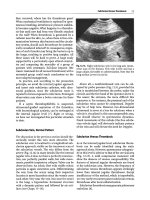
2.
Location. In ventilated patients in the supine
position, the effusion will collect in five areas
(Fig. 5.1). The diaphragm must be localized in
order to avoid any confusion with pleural effu-
sion (see
Fig.
5.6).
The effusion is searched for:
- Anterior to the
liver.
One must explore the last
intercostal spaces, where the pattern is char-
acteristic (Fig. 5.2). We immediately empha-
size this very upper location, at the intercostal
spaces.
- Surrounding the spleen, with the same com-
ment
(Fig.
5.3).
- At the flanks.
- In the pelvis (Douglas pouch) (Fig. 5.4, and
see
Fig.
9.13,
p
59).
- Morrison's pouch. In our
experience,
clinical-
ly relevant effusions located at Morrison's
pouch, a familiar area but very rarely visible
when isolated in a supine patient,
are
anecdo-
tal or redundant.
3.
The shape is highly characteristic. The limits of
the collection are concave outside (Fig.
5.5)y
since they surround the intraperitoneal struc-
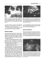
Fig.5.1.
The
five
areas where peritoneal effusion should
be searched for: (A) right hypochondrium, (B) right
flank,
(C)
pelvis,
(D)
left
flank,
(E)
left hypochondrium.
Note that
arrows
A and
E
are located in the intercostal
spaces,
not under the ribs as classically done
28 Chapters Peritoneum
Fig. 5.2. Prehepatic effusion. Here anechoic small ef-
fusion, whose thickness varies with the respiratory
cycle. A peritoneal effusion can reach this location,
and an exploratory puncture at this level is highly con-
tributive
Fig. 5.5. Substantial pelvic effusion. Note its concave
limits,
which underline the bowel loops. The effusion
allows
a
very fine analysis of
the
bowel structures. Here,
the wall is fine and regular, without
villi,
i.e., of the ileal
type.
The content is echoic and homogeneous
Fig.
5.3.
Suprasplenic effusion
(asterisk).
Although,
mini-
mal,
this
effusion is clearly identified, with
a
moon shape
between the spleen and diaphragm. Longitudinal scan
Fig.5.4. This substantial
pelvic
effusion isolates the uterus
(U)
and the ligamentum
teres.
Transversal subpubic scan
tures
(liver,
gallbladder, urinary bladder,
GI
tract,
etc.).
Conversely, encapsulated liquids (gallblad-
der, urinary bladder, renal cyst, digestive liquid,
etc.) have convex limits outside. A dynamic
analysis by scanning the area shows that a peri-
toneal effusion is an open structure, whereas an
encapsulated liquid gives a closed shape (this
image appears and then disappears during
scanning). In practice, a liquid image with con-
cave limits inside cannot correspond to free
peritoneal effusion. In the pelvis, a small effu-
sion may simulate, in a hasty test, a half-full uri-
nary bladder (see Fig.
9.13,
p 59).
4.
Dynamic patterns. A peritoneal effusion can be
shaped by the pressure of the probe or by respi-
ratory movements. The bowel loops seem to
swim within the effusion.
Ultrasound sensitivity
is
high for detection of even
minimal effusions [1]. A substantial effusion will
fill the entire peritoneal cavity and outline the
organs. Bowel loops thus become easier to analyze.
Perihepatic effusions can be distinguished from
pleural effusions provided the intercostal approach
is used, thus first detecting the diaphragm
(Fig.
5.6,
and see
Fig.
15.5,
p
98).
Nevertheless, if the subcostal
route is used, it must be known that only a pleural
effusion is located behind the inferior vena cava
(see Fig.
15.4,
p 97).
Last, ultrasound easily rules out what physical
examination can wrongly interpret as an effusion.
Ultrasound has often allowed us to avoid inserting
a needle in misleading cases, such as a case of
Hemoperitoneum 29
Fig. 5.6. Voluminous suprahepatic effusion, longitudinal
scan.
The
cupola
(arrow)
is separated from the liver (L)
by
the effusion, which means peritoneal location of
the
effusion. The anechoic pattern of the effusion is sug-
gestive of
a
transudate
Fig. 5.7. This patient had hydric dullness in the left iliac
fossa.
An
ultrasound examination precluded
a
puncture,
which would have been unproductive or even bloody.
It shows absence of peritoneal effusion and several ag-
glomerated
bowel loops
(/) with fluid inside
agglutination of bowel loops with liquid contents,
which gave dullness of
the
flank
(Fig.
5.7).
Diagnosis of the Nature of the Effusion
Fig.
5.8. Peritoneal effusion with multiple septations.
Patient with peritonitis due to pneumococcus. These
septations are
rarely visible
on
CT
tilation, right heart failure), capillary leakage, or
portal hypertension. Most of these etiologies have
characteristic ultrasound patterns (right heart
dilatation, hepatic structure of cirrhosis, etc.).
Peritoneal effusion in a patient suffering from
anasarca should not, in principle, be punctured,
but we have a more flexible attitude with this (see
Interventional Ultrasonography
Chap.
26).
Effusion containing a multitude of echoes in
suspension, as if in weightlessness, with dynamics
in rhythm with respiration cannot be
a
transudate.
Frank hemoperitoneum, peritonitis but also hem-
orrhagic ascites will give this pattern (see
Fig.
5.9).
One could call this sign the sign of the internal
dynamics, or better yet, the weightiessness sign,
but we have retained the plankton sign (see
Chap.
15).
Effusion with multiple septations indicates in-
flammatory effusion, generally, peritonitis
(Fig.
5.8).
Note that these septations are not visualized
with CT.
Although the echostructure of an effusion can
guide the diagnosis, our outlook is to practice easy
puncture, since the excellent risk-benefit ratio
makes this procedure particularly safe (see Inter-
ventional Ultrasonography
Chap.
26).
An anechoic effusion generally means transudate,
though exudate or hemoperitoneum can produce
the same pattern. Anechoic peritoneal effusion is
a very frequent finding in an ICU (38% in our
series),
sometimes limited to a small subphrenic
location. This usually occurs when there is an
obstacle to venous return (e.g., mechanical ven-
Hemoperitoneum
Patterns showing hemoperitoneum can be vari-
ous.
It can produce anechoic collection, can dis-
play a multitude of slowly moving echoes as if in
weightlessness, or plankton sign, which is immedi-
30 Chapters Peritoneum
Fig,
5.9.
In a longitudinal scan of
the
left hypochondri-
um,
this
mass,
which may
simulate
a
spleen in an exclu-
sively static
analysis,
is
in fact moving in a
slow
rhythm
(plankton sign). This pattern is the one of a recent
hemoperitoneum.
£,
stomach
Fig. 5.10.
The
gallbladder
(G)
of
this
patient
is
surround-
ed by a mass with an apparently solid pattern. This is
in fact
a
clotted hemoperitoneum
ately suggestive
(Fig.
5.9), and can also appear as a
large echoic, heterogeneous mass, caused by early
clotting (Fig. 5.10 and see Fig. 9.19, p 60). In this
case,
the collection appears solid and one of its
main characteristics, variations in shape, is no
longer found. It can thus be confounded within the
abdominal contents, which melts bowel loops,
omentum and various types of fat. Figure 20.24
proves that the blood can alter its echogenicity in a
few
seconds.
In some subtle
cases,
clotting appears
by successive layers, and can give the illusion of
bowel loops. This pattern, which can appear early,
could be problematic, since abundance and even
the existence of the hemoperitoneum can be inad-
equately
assessed.
This
trap can be easily bypassed,
however, with intercostal scans. Observation
shows that a majority of cases of clotted hemo-
peritoneum have a double component, with an
upper liquid that usually collects in the very
superior areas. A puncture, possibly within the
intercostal space, can on occasion confirm the
diagnosis.
On some occasions, ultrasound can show the
origin of the bleeding: splenic or hepatic rupture,
for example.
Note that in the trauma context, ultrasound is
increasingly replacing the traditional diagnostic
peritoneal lavage [2].
Peritonitis
Perforating peritonitis is a constant risk in the crit-
ically
ill.
Our experience in terms of acute abdom-
inal disorders shows that physical examination,
especially in sedated, aged patients, is notoriously
insufficient. Bedside plain abdominal radiographs,
always hard to obtain, generally generates useless
irradiation.
Observation suggests that, in a patient with any
acute diagnostic problems, detection of peritoneal
effusion is
decisive.
Minimal effusions are general-
ly more suspect that substantial ones. Secondary
development of a peritoneal effusion in a patient
whose hydric balance is maintained negative is
also suggestive of
a
complication.
The pattern of the effusion is suggestive when it
is echoic or has multiple septations (see Fig. 5.8).
Echoic layers surrounding the bowel loops are
seen when there is formation of pseudomem-
branes. Presence of gas within the collection [3]
seems a rare observation. Once more, a policy of
easy puncture can substantially clarify a clinical
situation that was complex or caused hesitation.
Surgical decisions can be made before clinical
signs become obvious.
Bowel analysis can also be rich in information
that can accelerate the decision for surgery (see
Chap.
6).
Thickened
walls
and abolished peristalsis
are some of the basic anomalies.
Last, detection of pneumoperitoneum will be
decisive here (see next section).
Interventional Ultrasonography 31
Pneumoperitoneum
Ultrasound's potential to detect pneumoperi-
toneum
is
rarely
exploited.
The
literature describes
an air barrier with a linear shape and acoustic
shadow in the extradigestive situation
[4],
visible
under the left
liver,
surrounding the gallbladder, in
the Morrison
pouch.
However,
the
abdomen is rich
in gas structures, and more precise signs should be
described.
1.
Gut sliding
[5].
It is possible to observe a sliding
movement, in rhythm with respiration, at the
abdominal level, which obviously corresponds
to the two peritoneal layers coming in contact.
We called this sign gut sliding in the interest of
brevity
(Fig.
5.11).
Gas
collects in the nondepen-
dent area of
the
abdomen,
i.e.,
in highly accessi-
ble areas in a supine patient. In
a
personal study,
gut sliding
was
present in
92
of
100
cases in nor-
mal subjects, and it was abolished in all seven
confirmed cases of pneumoperitoneum [5].
These data show that gut sliding can be
abolished in various conditions, for example,
because of peritoneal symphysis after some
surgeries, or because of an abolition of the
diaphragmatic course in critically ill patients.
A distended stomach will come against the
anterior
wall,
making gut shding hard to detect.
Consequently, analysis of gut sliding will con-
tribute more if the stomach was previously
localized in one way or another.
2.
Splanchnogram [5]. An extremely contributive
sign when gut sliding
is
absent
is
the detection of
anatomical structures such as the liver or bowel
loops (see Figs. 5.2-5.10), a familiar pattern
we called the splanchnogram in this context
when the probe is applied in a supine patient in a
sky-earth direction. It can refer to the liver or
even to the mesenteric fat, and can be called
a hepatogram or steatogram, for instance. This
observation obviously proves that no gas struc-
ture is interposed between the abdominal wall
and the visceral structures. A gas collection
would yield
a
complete acoustic shadow. In
a
per-
sonal study, absence of splanchnogram predict-
ed pneumoperitoneum with a 100% sensitivity.
3.
Other signs. Horizontal lines arising from the
peritoneal line are a basic sign of pneumoperi-
toneum, very sensitive, although not specific.
Detection of
a
peritoneal point is a very specific
sign. An equivalent of these signs is described in
Chap.
16, devoted to pneumothorax, since the
principle is the same.
Fig.
5.11.
Pneumoperitoneum.
Left
(real-time): massive
air barrier.
Right
(time-motion): this mode objectifies
the complete absence of
gut
sliding
In acute abdominal disorders, ultrasound can
replace the traditional radiograph showing cupo-
las or the positional radiographs, which are irradi-
ating and tiring (not to say dangerous when the
patient is asked to be upright). It is highly logical
that ultrasound
is
more sensitive than radiography
for early pneumoperitoneum.
In practice, note that a conserved peak gut slid-
ing or the visualization of visceral structures in a
sky-earth approach of the abdomen, allow pneu-
moperitoneum to be discounted, at the bedside.
Interventional Ultrasonography
When working with peritoneal effusion, we prac-
tice ultrasound-assisted puncture at the shghtest
doubt. Free of complications when done properly,
it has an excellent risk-benefit ratio. This is espe-
cially true in the critically
ill
patient, whose clinical
data rarely lead to a clear diagnosis. We find this
attitude paradoxically safer than the always risky
attitude of inferring the type of effusion from its
echostructure. In our routine, basic diagnoses are
regularly made, in spite of a misleading clinical
presentation.
We almost always use a 21-gauge green needle.
One major advantage of ultrasound is that one can
puncture far from the traditional landmarks. It
should be remembered that an intercostal tap can
be highly
contributive.
A
tap in the right iliac fossa
is classically forbidden, but is for us very common-
place: ultrasound shows that a Uquid collection
is interposed before the cecum. Ultrasound even
makes it possible to puncture the forbidden area
located at the level of the epigastric vessels, since
these vessels can be clearly identified
(Fig.
5.12).
32 Chapters Peritoneum
hypothesis, which seems confirmed by real-time
ultrasound observation, is that the needle drives
back a loose parietal layer without piercing it. In
this case, persisting in inserting the needle to the
end could lead to piercing undesirable structures
(bowel loops, iliac vessels, etc.). Ultrasound guid-
ance is required but, even here, some procedures
remain dehcate.
References
Fig 5.12. Transverse paraumbilical scan. Two tubular
parietal structures can be seen: the epigastric vessels
(arrows).
Note the peritoneal effusion deeper
The procedure itself is simple: one almost always
performs the tap just after ultrasound location
(see Chap. 26).
It is sometimes difficult to puncture very local-
ized effusions in the pelvis of elderly patients. One
Ferrucci
JT,
Vansonnenberg E (1981) Intra-abdomi-
nal
abscess.
JAMA
246:2728-2733
Rose
JS,
Levitt
MA,
Porter
J
et al (2001) Does the pre-
sence of ultrasound really affect computed tomogra-
phic scan use? A prospective randomized trial of
ultrasound in trauma.
J
Trauma 51:545-550
Taboury J (1989) Echographie abdominale. Masson,
Paris,
pp 246-249
Gombergh R (1985) Atlas illustre des indications
classiques et nouvelles de Techographie. Polaroid,
Paris
Lichtenstein
D,
Meziere
G,
Courret JP
(2002).
Le
glis-
sement peritoneal, un signe echographique de pneu-
moperitoine. Reanimation
11
[Suppl3]:165
CHAPTER
6
Gastrointestinal Tract
Ultrasound analysis of the GI tract is not routine
and is rarely listed in abdominal ultrasound
reports. The bowel is, in fact, often considered a
hindrance to the analysis of deeper structures.
However,
its
analysis can be decisive in the critical-
ly ill.
Bowel
analysis,
it is
true,
is conditioned
by
the
presence of gas, and is somewhat hazardous
(Fig. 6.1).
Nevertheless,
it
is
extremely rare that one
cannot see at least a small part of the 8 m of the
abdominal
bowel.
Nearly every part of the GI tract
can be disturbed by acute disorders.
Normal Ultrasound Anatomy
Bowel wall thickness, practically unchanged from
the stomach to the colon, ranges from 2 to 4 mm
[1].
Some authors describe several layers [2].
Abdominal Esophagus
The esophagus penetrates the abdominal cavity just
anterior
to
the
aorta.
The
frank acoustic shadow of a
gastric tube serves as
a
practical landmark
(Fig.
6.2).
Stomach
The
vertical portion, or fundus, passes between the
liver and spleen
(Fig. 6.3).
It is often hard to visual-
ize by the anterior approach and we study it by a
lateral, trans-splenic approach. It can be observed
in the concavity of the spleen.
The horizontal portion, or antrum, should be
investigated by the epigastric approach, with a
rounded pattern when empty, or enlarged when
the antrum is filled with liquid
(Fig.
6.4).
Duodenum
The duodenal bulb follows the pyloric stricture.
The second duodenum descends vertically at the
contact of the gallbladder and surrounding the
Fig. 6.1.
The probe is applied on an abdomen affected
with meteorism. No deep structure can be identified,
since digestive gas stops the progression of the ultra-
sound echoes
Fig. 6.2.
Abdominal esophagus
(arrow)
anterior to the
aorta (A), behind the left hepatic lobe (L) and con-
tinuing up to the stomach (£). The frank posterior
shadow arising from the gastric tube
(arrow)
gives a
precise
landmark.
Transversal epigastric scan
34 Chapter
6
Gastrointestinal
Tract
Fig.
6.3.
Vertical portion of the stomach (£), clearly out-
lined by an anechoic fluid content. Longitudinal scan.
L,
left hepatic lobe
Fig.
6.15). The ileum has a tubular, regular pattern
(see Fig. 5.5, p 28). Observation shows that acute
disorders of
the bowel
affect the whole of
the
bowel.
Consequently, ultrasound analysis of an even small
portion can be rich in information. Many relevant
items can be extracted:
1.
Peristalsis gives a permanent crawling dynam-
ics,
with regular contractions [3]. A present
peristalsis can be objectified in a few seconds.
This is the usual pattern in the normal subject.
Prolonged observation (at least 1 min) seems
necessary to affirm abolition of peristalsis.
2.
Cross-sectional area, in our observations, the
normal caliper of the small bowel is approxi-
mately 12-13 mm.
3.
Contents can have either
a
homogeneous echoic
(see Fig. 5.5, p 28) or hypoechoic pattern (see
Fig. 6.15). The clinical relevance of this distinc-
tion is being investigated.
4.
Wall thickness ranges from 2 to 4 mm
[1].
Fine
analysis of the wall is greatly facilitated when
there is liquid contrast from both sides, i.e.,
peritoneal effusion associated with fluid con-
tent, two conditions often present in acute dis-
orders (see
Fig.
6.15).
Fig. 6.4. Horizontal portion of the stomach (£), just
under the liver. One can precisely measure the wall
thickness, describe an anechoic fluid content, and local-
ize the gastric tube (more by the frank acoustic shadow
[arrow]
than by the tube itself). Epigastric longitudinal
scan
Colon
The colon is a tubular structure with visible haus-
tra
(Figs.
6.5
and 6.6), without identifiable peristal-
sis.
Roughly, the ascending and descending colon
pancreas head. Duodenum patterns are variable
and should not be confused with pathological col-
lections.
A
prolonged observation will show filling
and emptying movements. The third duodenum is
visible between the aorta and the superior mesen-
teric artery.
Small Bowel
It is almost always possible to visualize at least
some loops of the small
bowel.
The jejunum is rec-
ognized by the endoluminal presence of villi (see
Fig.
6.5. The cecum (C) in a longitudinal scan. Fluid
sequestration makes the cecum easy to identify. The en-
tire GI tract is filled with huge amounts of fluid in this
patient in shock, reflecting major hypovolemia. This
disorder should be exploited, since it allows fine analy-
sis of the digestive wall