General ultrasound In the critically ill - part 7 pptx
Bạn đang xem bản rút gọn của tài liệu. Xem và tải ngay bản đầy đủ của tài liệu tại đây (1.69 MB, 20 trang )
References lis
8. Steier M, Ching N, Roberts
EB,
Nealon TF Jr (1974)
Pneumothorax complicating continuous ventilatory
support.
J
Thorac Cardiovasc Surg 67:17-23
9. Holzapfel L, Demingeon G, Benarbia S, Carrere-
Debat
D,
Granier
P,
Schwing
D
(1990) Diagnostic du
pneumothorax chez
le
malade presentant une
insuf-
fisance respiratoire aigue. Evaluation de Tincidence
en decubitus lateral. Rean Soins Intens Med Urg
1:38-41
10.
Lichtenstein D (1997) L'echographie pulmonaire:
une methode d'avenir en medecine d'urgence et de
reanimation ? (editorial) Rev Pneumol Clin 53:
63-68
11.
Lichtenstein
D,
Lascols N, Prin S, Meziere G (2003)
The
lung
pulse:
an early ultrasound sign of complete
atelectasis. Intensive Care Med 29:2187-2192
12.
Lichtenstein D, Holzapfel L, Frija J (2000) Projec-
tion cutanee des pneumothorax et impact sur
leur diagnostic
echographique.
Rean
Urg 9
[Suppl
2]:
138
13.
Lichtenstein D,Menu
Y
(1995)
A
bedside ultrasound
sign ruling out pneumothorax in the critically ill:
lung sliding. Chest 108:1345-1348
14.
Rantanen NW (1986) Diseases of the thorax. Vet
Clin North Am 2:49-66
15.
Wernecke
K,
Galanski
M,
Peters
PE,
Hansen
J
(1989)
Sonographic diagnosis of pneumothorax. ROFO
Fortschr Geb Rontgenstr Nuklearmedl50:84-85
16.
Targhetta R, Bourgeois JM, Balmes P (1992) Ultra-
sonographic approach to diagnosing hydropneu-
mothor
ax.
Chest 101:931-934
17.
Lichtenstein D, Meziere G, Biderman P, Gepner A
(2000)
The
lung
point:
an ultrasound sign specific to
pneumothorax. Intensive Care Med 26:1434-1440
18.
Lichtenstein D, Meziere G, Biderman P, Gepner A
(1999) The comet-tail artifact, an ultrasound sign
ruling out pneumothorax. Intensive Care Med
25:383-388
19.
Lichtenstein D, Meziere G, Biderman P, Gepner A,
Barre 0 (1997) The comet-tail artifact: an ultra-
sound sign of alveolar-interstitial syndrome. Am J
Respir Crit Care Med 156:1640-1646
20.
Chiles
C,
Ravin
CE
(1986) Radiographic recognition
of pneumothorax in the intensive care unit. Crit
Care Med 14:677-680
21.
Sahn SA, Heffner JE (2000) Spontaneous pneumo-
thorax. New Engl
J
Med 342:868-874
CHAPTER
17
Lung
»The
lung
is
a
major
hindrance for the
use
of ultrasound at the
thoracic leveU
TR Harrison, Principles of Internal Medicine,
1992,
p.
1043
»Ultrasound
imaging
is not
useful for
evaluation
of the pulmonary parenchyma«
TR Harrison, Principles of Internal Medicine,
2001,
p
1454
»Most
of the
essential ideas
in
sciences
are fundamentally
simple
and can,
in
general,
be explained
in a
language which can
be
understood
by
everybody«
Albert Einstein, The evolution of physics, 1937
»Le
poumon ,
vous
dis-je!« (The lung / tell you!)
Moliere, 1637
In daily practice, examination of the lung can be
approached by physical, radiological and CT
scan examination. Physical examination is mas-
tered by auscultation, nearly a two- century-old
technique
[1].
Chest radiography is a century-old
technique
[2].
CT
has been fully available since the
1980s
[3].
It is not usual to proceed to lung ultra-
sonography, since this organ is reputedly inacces-
sible to this method
[4,5].
Ultrasound artifacts are
in principle undesirable structures. Yet the ultra-
sound representation of the lung is made up sole-
ly of artifacts, which can explain this apparently
solid dogma (see Figs. 16.1-16.5 and 17.6-17.9).
The lung may be an aerated organ, but it is a vital
organ.
The ultrasound beam is, it is true, totally
stopped when it reaches the
lung,
or any
gas
struc-
ture.
We saw
in
Chap.
16
that the numerous artifac-
tual signals generated by the gas structures can be
described and differentiated from each
other.
They
can
be
classified into A,
B,
Z
lines.
Indeed, obser-
vation shows that the pathological lung basically
differs from the normal lung.
One application has already been analyzed, the
diagnosis of pneumothorax. It
is,
in
a
way,
an ultra-
sound of the »non-lung«. Lung sliding and lung
rockets (see Chap. 16) indicate that the very lung
surface is visualized.
The Normal Lung Pattern
The lung ultrasound technique was described in
Chap.
15 and the normal pattern of the lung in
Chap.
16.
Let us recall the essential
points:
the nor-
mal lung signal consists of
one
dynamic
sign,
lung
sliding, and one static sign, the
A
line, exclusive or
predominant.
In diseased lung, virtually any disorder gives a
particular signal. Alveolar consolidation, atelecta-
sis,
interstitial syndrome,
abscess,
even pulmonary
embolism all have a characteristic pattern.
Alveolar Consolidation
Numerous terms are used in daily practice such as
alveolar syndrome, alveolar condensation, density,
infiltrate, parenchymatous opacity, pneumonia,
bronchopneumonia, pulmonary edema or even
atelectasis (a term often misused). This profusion
may indicate a certain diagnostic uncertainty.
»Hepatization« is an interesting word in the ultra-
sound field, since the lung and the liver have a sim-
ilar pattern. The term »alveolar filling« refers to a
nonretractile cause. The only and simple term we
use
is
»alveolar consolidation«,
since
this term does
not involve an etiology (infectious, mechanical,
hydric).
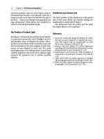
From the moment the consolidation reaches the
visceral pleura, lung consolidation will be perfect-
ly explorable with a short surface probe (Fig. 17.1).
The consolidation can
be
in contact with the pleur-
al line or be visualized through a pleural effusion
(see Fig. 15.7, p 99). As early as 1946, Denier, the
father of ultrasound, described this possibility
[6].
Ultrasound's potential was defined in the
meantime
[7-9],
but CT correlations are rarely
available.
Alveolar Consolidation 117
Fig.
17.1.
This
CT
scan of an alveolar consolidation shows
a large pleural contact at the posterior aspect of the lung,
a condition necessary to make this consolidation acces-
sible to ultrasound. This pleural contact is present in
almost all alveolar consolidations seen in acute patients
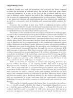
Fig.
17.3.
Massive alveolar consolidation of the lower
right lobe, longitudinal scan of the lower intercostal
spaces.
Hyperechoic opacities are
visible,
punctiform at
the
topy
linear at the bottom. They indicate air bron-
chograms
Fig.
17.2.
Massive alveolar consolidation of
the
lower left
lobe.
The acoustic barrier that is normally expected is
replaced with a large tissular supraphrenic mass. This
consolidation is substantial. If one takes, in this single
scan, a measure in the core-surface axis (vertical on the
image),
the value is 9
cm.
The measure in the horizontal
axis of the
image,
i.e.,
in the craniocaudal
axis,
is
8.5 cm
here.
These dimensions indicate major injury (a conso-
lidation index of
76.5).
Note also the homogeneous pat-
tern of
the
consolidation. Pleural effusion and air bron-
chogram are not visible. Longitudinal scan of the left
base,
lateral approach
In our observations, alveolar consolidation yields
a pattern characterized by the following items:
1.
Tissue pattern. Instead of the usual air bar-
rier, a real image, whose echostructure is a
reminder of the hepatic parenchyma, is
observed (Fig. 17.2).
2.
Boundaries. The superficial boundary is regu-
lar, since it is the visceral pleura, i.e., the pleu-
ral line in the absence of effusion. The deep
boundary can be ragged (the junction between
consolidated and aerated parenchyma) or
regular, when the whole lobe is involved.
3.
Dynamics. The consoUdation can have a glob-
al dynamics along the craniocaudal axis or no
dynamics at all, but no dynamics in the core
superficial area as in pleural effusion (see
Fig.
15.8,
p 99).
4.
Echostructure.
4A. Air bronchograms. The consolidation can
include numerous punctiform or linear hyper-
echoic opacities, obviously corresponding to
the air bronchograms (Fig. 17.3). These bron-
chograms, when present, are either dynamic
or static:
4A1.
The dynamic air bronchogram (Fig. 17.4).
Visualization of a dynamics within an
air bronchogram has clinical relevance:
the air present in the bronchi is subject
to a centrifuge inspiratory pressure
resulting in its movement toward the
periphery. An air bronchogram is thus
in continuity with the gas inspired by
the patient (either spontaneously or
through mechanical ventilation). In other
words, a dynamic bronchogram con-
solidation (DBC) indicates that the con-
solidation is not retractile: atelectasis
118 Chapter 17 Lung
Fig.
17.4.
Demonstration of dynamic air bronchogram.
The hyperechoic punctiform images, which indicate
the air bronchograms within alveolar consolidation (see
Fig. 17.2), happen to show an inspiratory centrifuge
motion. Time-motion mode perfectly highlights this
dynamics
(7,
inspiration. £, expiration). This exclusively
ultrasonic feature affirms the nonretractile character of
this alveolar consolidation
can be ruled out. To detect the dynamic
air bronchogram, the bronchus must be
in the precise axis of the probe. The
operator must avoid confusion with
false dynamics such as the out-of-plane
effect. This effect will give the erroneous
impression that the bronchograms light
up:
this is a different dynamics.
A consolidation is often associated with
an abolition of lung sliding, probably
by a decrease in lung expansion. This
motionlessness of the lung is a fortu-
itous condition facilitating the dynamic
analysis of its content.
4A2.
The static air bronchogram. When no
dynamics is observed on an air bron-
chogram, we speak of static bronchogram
consolidation
(SBC).
This pattern means
either that the air bubble is trapped and
isolated from the general air circuit
(before being dissolved) or that the
observation is not correctly located. In
the first case, it is tempting to see a sign
of atelectasis there, with air still trapped
in the bronchi. A study has confirmed
that a dynamic air bronchogram was
never observed in case of atelectasis,
whereas it was observed in 60% of cases
of alveolar consolidation of infectious
origin [10].
4A3.
Consolidation without visible bron-
chogram. The consolidation can be com-
pact, exclusively tissue-like. We then
speak of consolidation with no bron-
chogram, or NBC (see Fig. 17.2).
4B.
Signs of abscess. When the volume of the
consolidation is substantial, it is possible to
scan this area, in order to check for the homo-
geneous pattern (air bronchograms except-
ed).
An abscess can then be detected (see
»Abscess« p 125).
5.
Location of the consolidation, the consolida-
tion can be precisely located, considering the
relation with the diaphragm, but also the
cutaneous projection. The usual location in a
supine, ventilated patient is the lower lobe,
i.e., the lower half of the lateral zone, or more
posterior. Anterior location is rare, except in
complete atelectasis. In case of community-
acquired pneumonia, the location can be any-
where. The lower anterior half corresponds to
middle-lobe pneumonia. Pneumonia due to
pneumococcus usually has extensive contact
with the wall, often anterior.
6. Volume. Scanning makes it possible to rough-
ly evaluate the volume of the consolidation.
We have found it practical to measure only
two dimensions in a single longitudinal scan.
For instance.
Fig.
17.2 shows a substantial con-
solidation, with a 90-mm core-to-superficial
length, and an 85-mm craniocaudal height.
7.
Details. The following signs may or may not
have consequences on the etiological diagno-
sis of the consolidation.
- The C lines. A real, tissular image touching
the surface, with a size on the centimeter
scale or less, roughly pyramidal or cupola-
shaped (hence the C for cupola), is a small
alveolar node, although interstitial disor-
ders (with nodules) may give this pattern
(Fig. 17.5).
- Satellite images. A pleural effusion is often
associated with consolidation. When it is
not, we speak of dry consolidation.
The areas near the alveolar consolidation
can have an interstitial pattern (with B
lines;
see below) or a normal pattern, with
A
lines.
- The dynamics but also the location of the
hemidiaphragm should be described.
- A deviation of the nearby organs may be
informative.
If the definition of the alveolar consolidation
includes detection of a tissular pattern, with a reg-
Acute Interstitial Syndrome 119
Acute Interstitial Syndrome
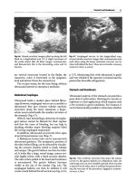
Fig.
17.5. The
pleural line
is
interrupted
by
a
centimeter-
scale
image,
concave
in depth
(M).
This
is a
C
line,
a
sign
of
very distal
alveolar
syndrome,
or
sometimes
a
nodule
ular superficial boundary and an irregular deep
boundary, with craniocaudal or abolished dynam-
ics but without a sinusoid sign, and with more or
less hyperechoic punctiform opacities, sensitivity
of ultrasound is 90% and specificity
98%
when CT
is taken as the gold standard [11].
Our search technique varies as a function of the
possibility of moving the patient and the thera-
peutic consequence. In supine patients, stage 2 or
stage
3
investigation is usually sufficient (see p 97).
Stage 4 is most often carried out in order to make
the most exact correlations with CT, but the
additional information rarely alters therapeutic
plans.
Pitfalls
The distinction between complex pleural effusion
and alveolar consolidation is usually easy (see
Chap.
15).
The sinusoid sign,
a
deep boundary pat-
tern, air bronchograms, especially when dynamic,
are decisive signs. In very rare cases, it is impossi-
ble to distinguish the solid part from the fluid part
(the ultrasound dark
lung;
see Chap.
15,
p 102).
Abdominal fat should
be
very similar to alveolar
consolidation, but it is a good habit to first locate
the hemidiaphragm for easy distinction.
Is such a long description of ultrasound pat-
terns relevant, since radiograph is already avail-
able? The answer is yes, above all because alveolar
consolidations, especially of the lower lobes, can
easily be invisible on bedside radiographs. Second,
because ultrasound gives an approach by sections,
which allows accurate recognition and measure-
ment of fluid, alveolar syndrome, abscesses, etc.
Pleural effusions, pneumothorax and alveolar con-
solidation are therefore accessible to ultrasound, in
spite of
the
reputation of non-feasibility at the tho-
racic
level.
However, the performance of ultrasound
does not stop
here.
Analyzing air artifacts alone, the
very ones that supposedly made thoracic ultra-
sound impossible, make it possible to go further.
Therefore and paradoxically,
the
detection of an
interstitial syndrome is indeed the concern of
ultrasound. This application was announced in
1994 [12] and confirmed in 1997
[13]. We
will first
see how to detect
it,
then why to detect it.
Acute interstitial syndrome involves a wide
range of
situations,
including adult respiratory
dis-
tress syndrome, cardiogenic pulmonary edema,
bacterial or other pneumonia, chronic interstitial
diseases with exacerbation.
The interstitial syndrome is not known to give
physical signs, nor is a bedside chest radiograph
expected to show interstitial changes, without
exception. Even in a good-quality radiograph
taken in an ambulatory patient, this diagnosis is
particularly difficult, subjective, and a single read-
er can interpret differently from one day to the
next [14].
The Ultrasound Signs
Elementary sign, the comet-tail artifact arising
from the pleural
line,
well defined, erasing
A
lines,
in rhythm with lung sliding and spreading up to
the lower edge of the screen without fading, i.e., the
ultrasound
B
line (Fig.
17.6).
This description dis-
tinguishes the
B
line from the
Z
line (Fig. 17.7) and
the
E
line (see
Fig.
16.11,
p
113).
The elaborated sign is the visualization of sever-
al B lines in one longitudinal view between two
ribs.
This
pattern
is a
reminder of
a
rocket after lift-
off, and
is
called lung rockets
(a
practical
label).
The
distance between two
B
lines at their origin
is 7
mm
or
less.
When it is 7 mm, one speaks of
B7
rockets
(Fig. 17.8). When this distance is less, usually
around 3 mm, the B lines are twice as numerous,
and
we
speak of
B3
lines or B+ lines (Fig. 17.9).
The pattern that defines interstitial syndrome is
the presence of lung rockets wherever the probe is
applied at the anterolateral chest wall in a supine
or half-sitting patient. The term here is »diffuse
rockets«,
which implies
a
bilateral anterior and lat-
eral pattern, from apex to
bases.
An isolated
B
line
has not yet been shown to be pathological, to our
120 Chapter 17 Lung
Fig.
17.6.
Example of a b line. Arising from the pleural
line,
an isolated comet-tail artifact, well defined, laser-
like,
is spreading up to the edge of the screen without
fading and erases
A
lines
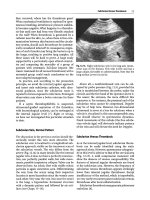
Fig.
17.8.
Five B lines are identified in this longitudinal
scan of the anterior chest
wall.
They
define
a
pattern remi-
niscent of a rocket at
lift-off.
Artifacts are separated from
each other by an average distance of
7
mm. Lung rockets
are an ultrasound elementary
sign
of interstitial syndrome
Fig. 17.7. Three vertical, ill-defined artifacts arising
from the pleural line and fading after a few centimeters
were defined. These artifacts are Z lines, a type of air
artifact which should never be confounded with
B
lines.
Because of the clinical importance of this distinction, we
prefer to dupHcate Fig.
16.3
here.
Arrows:
A
line
Fig.
17.9.
Massive lung rockets. Here, seven comet tails
can be counted and the distance between each comet tail
is approximately
3
mm. This pattern is quasi-specific of
ground-glass
areas.
In our experience, this pattern indi-
cates acute interstitial syndrome
knowledge. In order to specify that a B line is iso-
lated, we speak of b line (lower case »h«).
Value of Lung Rocket Signs
In a study including 81 cases of massive alveolar-
interstitial syndrome and 119 controls without
alveolar or interstitial changes, ultrasound sensi-
tivity based on the previous definition was 92.5%
and specificity 94% [13]. Note that feasibility was
100%.
Which structure is at the origin of the comet-
tail artifact? Nine items can clearly define it:
1.
The comet-tail artifact indicates an anatomical
element with a substantial acoustic impedance
gradient with the surrounding elements [15],
for instance, air and water.
2.
The detected element is small, inferior to the
resolution power of ultrasound, which is rough-
ly
1
mm, hence not directly visible.
3.
This structure is visible at the lung surface.
4.
It is visible all over the lung surface.
Acute Interstitial Syndrome
121
5.
The element is separated from each other by
7 mm.
6. It is present at the last intercostal space in about
one-quarter of normal subjects; see Chap. 16.
7.
It is correlated with pulmonary edema.
8. It vanishes with the treatment of the pulmonary
edema (in a few hours when the edema has car-
diogenic origin).
9. It is also present in any interstitial disease.
All these criteria, in a way casting out the nines,
are the precise description of thickened interlobu-
lar
septa.
The hypothesis that lung rockets indicate
thickened septa has been confirmed: in fact, CT
correlations showed that normal structures stop a
few centimeters before the lung surface, whereas
thickened interlobular septa reach the periphery,
i.e., the visceral pleura (Fig. 17.10). In this view-
point, the ultrasound B lines appear as an ultra-
sound equivalent of the familiar Kerley's B lines
[16].
Note that Kerley's
B
lines are observed at the
bases of 18% of thoracic radiographs of healthy
subjects
[17].
This number is not very far from the
28%
of lung rockets present at the last intercostal
space of healthy subjects [
13].
The difference prob-
ably indicates a slight superiority of ultrasound to
detect these very fine elements.
The potential of ultrasound to detect water
explains the high performance.
Here,
water is pre-
sent in
a
very small amount,
a
submillimeter thick-
ness.
A thickened interlobular septum is 700 |im
thick, versus
300
|im for
a
normal
septum.
However,
this infinitesimal amount of water is surrounded
by air. This mingling is the essential condition
required to generate the ultrasound
B
lines.
In
addi-
tion, clinical observation shows that the interstitial
syndrome, especially in pulmonary edema (either
cardiogenic or lesional) is a diffuse disorder. This
makes its detection immediate wherever the probe
is applied. It should be understood that interstitial
edema involves all interstitial
tissue,
the superficial
part of it being accessible to ultrasound.
Pathological
and
Nonpathological Locations
of Lung Rockets
• The b lines can be occasionally observed in
normal subjects, possibly indicating the small
scissura.
• Lung rockets localized at the last intercostal
space are found in
28%
of normal subjects [13].
• Lung rockets located at the lateral wall but
including more than two intercostal spaces
Fig.
17.10.
CT scan of massive alveolar-interstitial syn-
drome. Thickened interlobular
septa
are
visible
touching
the anterior surface
(arrows).
In a normal subject, no
dense structure is visible at the anterior or posterior
aspects
above the diaphragm should be considered
abnormal. The label used is »extensive lateral
rockets.« In general, more posterior analysis
usually shows alveolar changes.
• Posterior lung rockets in supine patients are
usual, and possibly indicate that the lung water
preferentially accumulates in the dependent
areas.
Analysis of CTs without lung disorders
clearly shows these dependent changes. On the
other hand,
the
absence of posterior rockets in a
chronically supine patient is singular, and may
mean, if validated, substantial hypovolemia.
Clinical Relevance
of
Lung Rockets
Ultrasound recognition of the interstitial syn-
drome has several implications,
a
majority of them
already validated.
Ultrasound Diagnosis
of
Pneumothorax
The recognition of lung rockets immediately rules
out complete pneumothorax [18]. Note that this
item is basic when lung sliding is very weak or
absent, which is a common finding in ARDS.
Absence of anterior lung rockets in a patient with
a white lung on radiography
is
suggestive of pneu-
mothorax, but far from specific.
122 Chapter
17
Lung
Ultrasound Diagnosis of Pulmonary Edema
Diagnosis Before radiography
In the emergency situation, the physical examina-
tion can be atypical in a dyspneic patient with pul-
monary edema. We know that interstitial edema
precedes alveolar edema [19]. Crackles can be
absent at the early stage [20] or
be
replaced by sibi-
lants in cardiac asthma. Last, fine auscultation can
be illusory in a ventilated patient.
In all these cases, ultrasound provides early
diagnosis.
Pararadiological Diagnosis
Ultrasound can reinforce the radiograph, once
read.
• The chest
X-ray,
even
of good
quality,
can be
dif-
ficult to interpret. Let us cite again Fraser, who
notes that some radiographs that were inter-
preted normal on Monday are labeled intersti-
tial on Friday, and by the same reader [14].
• The radiograph can be taken too
early.
A
good-
quality radiograph, when taken too
early,
can be
subnormal, even in genuine, very severe pul-
monary edemas
[21,22].
The
radiograph should
clear evidence of advanced stages of edema.
• The radiography can be ill-defined. This is the
usual case in emergency. The radiograph is
known not to be accurate enough to detect signs
of left heart dysfunction. X-ray sensitivity in
detecting interstitial edema can range between
18%
and
45%
[23].
Bedside chest radiography is
known to be insufficient for the diagnosis of
interstitial syndrome
[24].
In addition, Kerley
B
lines have been described in pulmonary edema
and exacerbation of
COPD
[25].
Nonradiological Diagnosis
When the radiography is not readily available such
as in pre-hospital medicine, or, in rare instances, in
the hospital
itself,
or when radiography
is
not indi-
cated such as in pregnant women or children, and
possibly in each patient, ultrasound can
find
a
place.
Differential Diagnosis Between Cardiogenic
Pulmonary Edema and Exacerbation of Chronic
Obstructive Pulmonary Disease
Presence or absence of lung rockets generally
places a dyspneic patient immediately into one of
these two groups: diffuse interstitial syndrome or
absence of interstitial syndrome. Diffuse bilateral
lung rockets is a pattern seen in 100% of cases in
cardiogenic acute pulmonary edema vs 8% of
cases in patients with exacerbation of
COPD
[26].
Differential Diagnosis Between Lesional
and Cardiogenic Pulmonary Edema
Determining the lesional or cardiogenic origin of a
white lung
is a
frequent
task.
To
oversimplify, water
in cardiogenic pulmonary edema is submitted to
hydrostatic pressure and moves up to the nonde-
pendent areas. In lesional edema, water passively
descends to the dependent
areas.
These
movements
will have a sonographic outcome: the absence of
diffuse anterior lung rockets when there are white
lungs on the radiograph are highly suggestive of
lesional edema (study in progress).
Diagnosis of Pulmonary Embolism
We will see in a dedicated section that visualizing
lung rockets is highly uncommon in this disorder.
Qualitative Estimation of Wedge Pressure
We will not debate on whether wedge pressure
provides pertinent or totally outdated informa-
tion. Some turn their back on this information
judged obsolete. The reader can refer to p 180 in
Chap.
28, where the problem is detailed more
extensively. Our wish is to provide noninvasive
data that correlated with wedge pressure for the
intensivist who can find such a parameter useful.
Observation shows that the absence of lung
rockets is clearly correlated with low wedge pres-
sure.
This
relies on elementary
logic.
The
same log-
ic indicates that lung rockets are a reflection of
lung
water.
Note that neither right-heart catheteri-
zation nor the transesophageal echocardiography
provide direct representation of the lung water.
Lung rockets are indeed a tracer that directly
indicates edematous septal engorgement. In this
application, lung ultrasonography will have the
advantage of exploring the primary cause of the
pulmonary edema, which is as a rule radio-occult.
Of course, septa can be thickened by inflamma-
tion, and the relation between lung rockets and
high wedge pressure is less correlated.
Atelectasis 123
Monitoring Fluid Therapy
The analysis of lung rockets may have an appar-
ently unexpected relevance directly derived from
the previous wedge pressure. First observations
show that the appearance of lung rockets during
fluid therapy is the first change, which occurs
before any others (crackles, desaturation or radio-
graphic
changes).
This is
logical since
gas
exchanges
occur at the fine, not yet edematous area of the
alveolocapillary membrane
[27].
Surface lung ultra-
sonography will indicate that the septa are
dry,
and
that a safety margin exists if fluid therapy
is
envis-
aged. We should remember that the radiological
signs of interstitial change precede the clinical
signs of pulmonary edema [28].
Evaluation of Lung Expansion
The movement of
the
pathological comet-tail arti-
facts can be analyzed and measured. This can give
an accurate index of the lung expansion and can
have clinical implications. The normal lung excur-
sion is 20 mm at the bases in ventilated patients. It
can be completely aboUshed in pathological condi-
tions.
Monitoring the Ventilatory Parameters in ARDS
According to recent studies of ARDS patients with
diffuse attenuations on
CT,
a positive end-expira-
tory pressure can induce alveolar recruitment
without overdistension, whereas in lobar patients,
alveolar recruitment is modest and overdistension
of previously aerated areas occurs
[29].
A
relation-
ship can be estabHshed between overdistension
and lung
rockets.
In
ARDS,
the anterior pattern can
display lung rockets or A-line areas. B+ lines are
correlated to ground-glass areas
[13].
This notion
can be of interest for the intensivist who alters the
management of the patient as a function of the
presence or absence of ground-glass areas (study
in progress).
Diagnosis of Nonaerated Lung
The detection of lung rockets in a posterior
approach of a supine patient
is
equivalent to ruling
out alveolar consolidation, since an overwhelming
majority of cases of alveolar consohdation reach
the posterior pleura. In these cases, the posterior
aspect of the lung is interstitial, but not alveolar.
We previously stated that posterior lung rockets
are quasi-physiological in chronically supine
patients.
Following this
logic,
if alveolar consohda-
tion is detected in a dependent area, pleural effu-
sion can be ruled out as well.
Atelectasis
Ultrasound patterns in atelectasis have not been
extensively described. Artifacts and real image
analysis
is,
however, possible.
A
number of obser-
vations can describe several aspects:
• An immediately available and reliable pattern
is the lung pulse. This sign was described in
Chap.
16 (see Fig.
16.5,
p 108). The lung pulse,
which in addition rules out pneumothorax, can
be observed within the first seconds of complete
atelectasis.
A
characteristic example is realized
in case of selective intubation. Selective intuba-
tion creates a sudden and complete left atelecta-
sis.
The left lung is aerated, and remains thus
a certain time, if an early radiograph is per-
formed. Paradoxically, the lung pulse ultra-
sound sign is immediately present in 90% of
cases
[30].
A
lung pulse can be visible or invisi-
ble,
but the abolition of lung shding is constant,
since it is observed in 100% of cases. In addi-
tion, the left hemidiaphragm descent is abol-
ished.
Eventually, the lung empties of its gas, and the
atelectasis becomes patent, i.e., visible on radio-
graphs. The consolidated lung is thus directly
analyzable using ultrasound (Fig. 17.11).
Lung sliding is always abolished in complete
atelectasis.
The lung has a tissular pattern. Air bron-
chograms can most often be observed, but only
static air bronchograms should be observed [10].
The absence of any air bronchogram is
a
very indi-
rect sign of atelectasis.
Fluid bronchograms have been described [31].
They would yield small anechoic tubular struc-
tures and be observed in obstructive pneumonia
only.
We
were not able to observe them, or to dis-
tinguish them from visible vessels, with our
5-MHz
probe.
Very characteristic signs of complete atelectasis
are all the signs indicating a loss of lung volume.
The intercostal spaces are narrowed. The hemidi-
aphragm is heightened above the mammary line.
The spleen or liver have a frank thoracic location.
The mediastinal attraction is one of the more
124 Chapter 17 Lung
Fig.
17.11.
Massive atelectasis of
the
right
lung.
Transver-
sal scan of the right anterior third intercostal space.
Instead of an acoustic barrier,
a
tissular image
is
visible.
It
shows complete consolidation of the upper right
lobe.
We
can observe the ascending aorta (A), the superior vena
cava (V) and
the
right pulmonary artery
{PA),
in
brief,
the
mediastinum, which is here frankly shifted to the right.
Other pathological points were noted in this ventilated
patient: static air bronchograms, phrenic elevation,
aboUshed lung sliding, and lung pulse among others
Fig. 17.12. The b line of the left image is completely
motionless.
A
time-motion view at the exact level of this
b line objectifies the disorder. A mobile b line would
escape at regular intervals outside the cursor line like a
pendulum, and would yield a succession of clear and
dark bands, and not this homogeneous clear pattern
(right image). This pattern indicates abolition of the
lung expansion
striking patterns (Fig. 17.11). The mediastinum,
usually difficult to access, is perfectly analyzable,
as during transesophageal examinations. This
serendipitous effect allows a clear analysis of usu-
ally hidden structures: the vena cava superior at
the right (see Fig.
12.20,
p
80),
the pulmonary artery
and its left and right branches, the pulmonary
veins,
and possibly the main bronchi can be ana-
lyzed. Before the treatment of an atelectasis, scan-
ning the mediastinum is recommended. If time
lacks,
it is always possible to quickly record the
data on videotape, and quietly visualize the images
later, searching for venous or arterial thromboses,
mediastinal tumors, etc.
Acute Pleural Symphysis
Using lung sliding and the comet-tail artifact has
allowed us to identify a frequent situation occur-
ring in severe disorders: abolition of lung sliding
without pneumothorax (Fig. 17.12). This situation
is particularly frequent in ARDS and massive
pneumoniae, especially those due to pneumococ-
cus.
Patients are generally on mechanical ventila-
tion. In a few cases we could check, inflammatory
adhesions of the lung stuck the visceral pleura
against the parietal pleura. It is important to know
acute pleural symphysis is possible in order not to
speak of pneumothorax in these cases. As a rule,
lung rockets or a lung pulse will often be present
here and thereby rule out pneumothorax.
The diagnostic relevance of this disorder may
be to provide an argument to differentiate lesional
from cardiogenic pulmonary edema. In cardio-
genic edema, only water transudates from the pleu-
ra, which cannot impair lung sliding. In lesional
edema, there is exudation of fibrin, which may
result in the pleural layers sticking.
As regards therapeutic relevance, for the
moment, one can only assume that acute pleural
symphysis will result in acute restrictive ventilato-
ry disorder. The appropriate therapy is another
matter. Note finally that other conditions can abol-
ish lung sliding: complete atelectasis or again pul-
monary fibrosis.
Pulmonary Abscess
This disorder is also explored successfully using
CT.
Bedside radiographs are usually inadequate,
Pulmonary Embolism 125
since the air-fluid level is not aligned by the X-
rays.
Ultrasound can be tried as often as necessary.
In fact, abscesses are most often peripheral and
benefit from a parenchymatous acoustic window.
An abscess within alveolar consolidation
appears as a hypoechoic, clearly defined, rather
regular image (Fig.
17.13).
A
collection of gas gives
strong echoes.
The air-fluid level is accessible to ultrasound if
the probe is applied at the patient's back and points
frankly toward the
sky.
The
screen will successively
display a fluid image then an air acoustic barrier
with a lapping boundary. This
assumes,
however,
a
levitation maneuver, which is in practice difficult
to
achieve.
A
more accessible maneuver is possible
(Fig. 17.14): the approach is as posterior as possi-
ble,
but without levitation maneuvers. Small
bumps are made in the bed. The fluid level will
thus be moved. As for bowel occlusion or hydro-
pneumothorax (see pp 39 and 111), the ultra-
sound translation will be strong, highly suggestive
dynamics: one can imagine the dynamics of a
shaken glass of
water.
This sign is called the sign of
the air-fluid
level,
or better, the swirl sign.
Fig.
17,13.
Within an alveolar consolidation, a hypo-
echoic rounded image is visible in this longitudinal
supraphrenic image of
the
right
base.
This
lung abscess
is
visible from the echoic
surroundings.
Located
20
mm
below the pleural line (and 30 mm beneath the skin),
this abscess
is
ready for ultrasound-guided aspiration
Pulmonary Embolism
Sometimes an obvious
diagnosis,
sometimes tricky,
pulmonary embolism remains a daily concern.
The abundance of protocols and algorithms indi-
cates that progress is indeed needed. Any help
should be studied with attention, especially if non-
invasive.
Cardiac and venous signs are detailed in the
corresponding chapters. Briefly, a dilatation of the
right ventricle is one of several signs, but right
heart analysis is frequently difficult in the emer-
gency room using surface ultrasound. Chapter 28
shows that this is not
a
hindrance. Venous signs are
found in a majority of cases (more than 80%) if
one makes the effort to search for them in the low-
er but also upper extremities in ICU patients.
At the lung
itself,
three signs can be described.
1.
The most striking sign in our experience is the
presence of a majority of
A
lines at the antero-
lateral chest wall. Absence of lung rockets was in
fact noted in 91% of 33 cases of severe pul-
monary embolism
[32].
This pattern is immedi-
ately suggestive in a patient without chronic
lung disease (asthma, COPD) with sudden dys-
pnea. This should not be surprising, as it is an
Fig.
17.14.
This figure is composed of two zones: one
fluid at the
right,
one
aerated at the
left.
A
roughly hori-
zontal line is thus created
(arrows).
Real-time would
show air-fluid
swirls.
In order to pick up this interface,
the ultrasound
beam
must first enter
the
fluid
zone
then
the air zone. Obviously, the probe should point to the
sky. CT showed a voluminous fluid-air collection in a
consolidated lower lobe
ultrasound equivalent of the usually normal
radiography. The advantage is immediate, bed-
side availability. Note that if
B3
lines are taken
into
account,
the
detection of
B3
lines has a neg-
ative predictive value of
100%
for the diagnosis
of severe pulmonary embolism; we are still
awaiting our first case.
A small, usually radio-occult pleural effusion
can be contributive.
126 Chapter
17
Lung
3.
Some authors describe small peripheral alveo-
lar images as indicating pulmonary infarction
[33].
We
have seen these patterns (see Fig. 17.5)
in less than 4% of cases in a personal series of
severe pulmonary
embolism.
Our explanation is
that distal small alveolar infarction may indicate
mild pulmonary embolism, a logical deduction,
since the smaller the embolism, the more distal
the disorder.
C
lines, as we have called this pat-
tern for
years,
are more often observed in severe
pneumonia with hematogenous extension in
our experience.
Routine use of lung ultrasound should rid the
intensivist of an old problem: should this patient
be transported to the CT room, or worse, to con-
ventional angiography? Should that patient in
shock be submitted to the risk of heparin therapy
or blind thrombolysis?
Phrenic Disorders
The diaphragm can be dealt with
here,
since it par-
ticipates in lung function.
The
diaphragm has been
described in
Chaps.
4
(see
Fig.
4.9,
p
22)
and
15
(see
Figs.l5.5,p98andl5.7,p99).
The normal inspiratory amplitude of the
diaphragm can be analyzed in a longitudinal scan
of the liver or the spleen. In spontaneous ventila-
tion in a normal subject, or in conventional
mechanical ventilation in a patient without respi-
ratory disorder, it is located between 10 and 15,
sometimes 20 mm. Note that a pleural effusion,
even substantial, does not affect this amplitude
even in mechanical ventilation.
An amplitude under 10 mm, approximately
5 mm, is pathological. Several factors possibly
explain a small or abolished phrenic amplitude:
pleural symphysis, atelectasis, low tidal volume, or
abdominal hyperpressure.
Ultrasound can recognize a phrenic paralysis, a
frequent complication in cardiac or thoracic surgery.
Transporting the patient to the radioscopy room can
be avoided. Phrenic paralysis yields these signs:
• Abnormal movement of the hemidiaphragm in
spontaneous
ventilation:
limited
(less
than
5
mm)
or absent amplitude, or paradoxical movement
• High, intrathoracic location of liver or spleen
• Very diminished or abolished lung sliding
• Absence of thickening of the hemidiaphragm
during inspiration,
a
subtle
sign,
not always easy
to
see,
and still theoretical (Fig. 17.15).
Fig.
17.15.
Phrenic
respiration.
These views
objectify
the
inspiratory thickening of the cupola, increasing from
4
to
6
mm.
£,
expiration.
I,
inspiration
Let us recall that the location of the hemidia-
phragm is a first step in any pleural or lung so-
nography.
Ultrasound in the Etiological Diagnosis
of
an
Alveolar-Interstitial Disorder
The ultrasound pattern alone can suggest certain
etiologies.
• Massive alveolar consolidation with dynamic
air bronchogram. In our experience, pneumonia
caused by pneumococcus yields a pattern of
massive alveolar consolidation, with a system-
atized location: the alveolar consolidation
appears all of a sudden, replacing aerated pat-
terns.
• Symmetric pattern associating mild dependent
consolidation, mild pleural effusion, diffuse
B-H
lung
rockets.
This symmetric pattern is the usu-
al association in acute cardiogenic pulmonary
edema.
• Alveolar consolidation without lung rockets.
Alveolar syndrome not associated with intersti-
tial syndrome is frequently observed in aspira-
tion pneumonia. This is a logical finding, since
aspiration pneumonia is a situation where al-
veolar lesions occur before interstitial lesions.
• Substantial alveolar consolidation without pleur-
al effusion.
A
massive consolidation without the
smallest pleural effusion probably has a precise
meaning. The pneumococcus seems to be asso-
ciated with this pattern.
• Exclusive diffuse lung rockets, no consolidation,
no pleural effusion. This particular profile has
References 127
been observed in miliary tuberculosis as well as
in pneumocystosis. Lung rockets are usually B3
type,
and present at the antero-latero-posterior
walls.
interventional Uitrasound
Some studies have dealt with the possibiHty of
parenchymal puncture for bacteriological investi-
gation purposes. Indeed, procedures were said to
be blind, since fluoroscopy was the only means of
locating the puncture [34]. If an area of alveolar
consolidation is recognized using ultrasound, the
precise area where the puncture should be done
will be indicated, at the bedside.
Since lung taps are made without ultrasound, let
us examine the advantages that ultrasound would
provide. First, lung sUding can be assessed. If the
lung is adhering to the wall, by pleural symphysis,
for instance, the risk of pneumothorax will theo-
retically be limited. This is the case for fixed alveolar
consolidations, i.e., consoUdations associated with
aboUshed lung sHding. Second, if the needle crosses
completely consoUdated lung without contact with
the airways, the risk of pneumothorax will clearly
fall.
Third, if the puncture is posterior, the heavy
lung will weigh its full weight over the
hole.
Using all
these precautions, it should be interesting to com-
pare the risk of pneumothorax with the rate of
pneumothorax that occurs under a plugged tele-
scopic catheter, an infrequent but possible complica-
tion. Fourth, the route is very direct: bacteria swarm
just a few centimeters deep below the skin, making
the risk of contamination very low. A plugged tele-
scopic catheter will take a very long route: risk of
contamination is a main concern. The ultrasound
approach has the advantage of an extremely simple
procedure, when compared to the invasive ones
(fiberscope, plugged telescopic catheter).
Technically, a fine 21-gauge needle should be
used.
A
substantial vacuum will be needed in order
to obtain a small drop of brown material. The best
results in our institution are obtained when the
syringe is directly sent to the laboratory, with the
needle inserted, and without additional fluid
(serum or other).
Community-acquired as well as nosocomial
pneumonia could be approached using the follow-
ing criteria: large pleural contact allowing good
ultrasound location, substantial consolidation,
and abolition of lung sliding. These criteria are
often present.
Large series will specify more fully where this
procedure should be placed. The other invasive or
semi-invasive procedures involve a small but pre-
sent risk, accuracy rates far from perfect and other
drawbacks (e.g., cost). Our series show a rate of
positive bacteriology of 50%. When positive, the
microbes usually swarm in the specimen sent to
the laboratory. With the previously described cri-
teria being present, pneumothorax never occurred
as a consequence of the procedure.
As regards pulmonary abscesses, ultrasound-
guided aspiration was described [35]. This allows
direct bacteriological diagnosis. Pleural symphysis
and the surrounding alveolar consolidation theo-
retically protects from risks of pneumothorax.
Ultrasound-guided aspiration is not yet proposed
in first line treatment, but should be reserved for
resistant or severe abscesses: those that are seen, by
definition, in the ICU.
References
1.
Laennec RTH (1819) Traite de Tauscultation
mediate, ou traite du diagnostic des maladies des
poumons et du coeur. J.A. Bresson 8c J.S. Chaude,
Paris
2.
Williams FH (1986) A method for more fully
determining the outline of the heart by means of
the fluoroscope together with other uses of this
instrument in medicine. Boston Med Surg J 135:
335-337
3.
Hounsfield GN (1973) Computerized transverse
axial scanning. Br
J
Radiol 46:1016-1022
4.
Friedman PJ (1992) Diagnostic tests in respiratory
diseases. In: Harrison TR (ed) Harrison's principles
of internal medicine. 12th edn. McGraw-Hill, New
York,
p 104
5.
Weinberger SE, Drazen JM (2001) Diagnostic tests
in respiratory diseases. In: Harrison TR (ed) Harri-
son's principles of internal medicine, 14th edn.
McGraw-Hill,
New
York,
pp 1453-1456
6. Denier A (1946) Les ultrasons, leur application au
diagnostic. Presse Med 22:307-308
7.
Weinberg B, Diakoumakis EE, Kass EG, Seife B,
Zvi ZB (1986) The air bronchogram: sonographic
demonstration.
Am J
Roentgenol 147:593-595
8. Dome HL (1986) Differentiation of pulmonary
parenchymal consolidation from pleural disease
using the sonographic fluid bronchogram. Radiolo-
gy 158:41-42
9. Targhetta R, Chavagneux R, Bourgeois JM, Dau-
zat M, Balmes P, Pourcelot L (1992) Sonographic
approach to diagnosing pulmonary consolidation.
J
Ultrasound Med 11:667-672
10.
Lichtenstein
D,
Meziere G, Seitz G (2002) Le »bron-
chogramme aerien dynamique«, un signe echogra-
128 Chapter 17 Lung
phique de consolidation alveolaire non retractile.
Reanimation
11
[Suppl]3:98
11.
Lichtenstein D, Lascols N, Meziere G, Gepner A
(2004) Ultrasound diagnosis of alveolar consolida-
tion in the critically ill. Intensive Care Med 30:
276-281
12.
Lichtenstein
D
(1994) Diagnostic echographique de
Toedeme pulmonaire. Rev Im Med 6:561-562
13.
Lichtenstein D, Meziere G, Biderman P, Gepner A,
Barre 0 (1997) The comet-tail artifact: an ultra-
sound sign of alveolar-interstitial syndrome. Am J
Respir Crit Care Med 156:1640-1646
14.
Fraser RG, Pare JA (1988) Diagnoses of disease of
the chest, 3rd edn. WB Saunders Company, Phila-
delphia
15.
Ziskin MC, Thickman DI, Goldenberg NJ, Lapa-
yowker MS, Becker JM (1982) The comet-tail arti-
fact.
J
Ultrasound Med 1:1-7
16.
Kerley
P
(1933) Radiology in heart
disease.
Br
Med
J
2:594
17.
Felson B (1973) Interstitial syndrome. In: Felson B
(ed) Chest roentgenology, 1st edn. WB Saunders,
Philadelphia, pp 244-245
18.
Lichtenstein D, Meziere G, Biderman P, Gepner A
(1999) The comet-tail artifact, an ultrasound sign
ruling out pneumothorax. Intensive Care Med 25:
383-388
19.
Staub NC (1974) Pulmonary edema. Physiol Rev
54:678-811
20.
Braunwald E (1984) Heart disease.
W.B.
Saunders,
Philadelphia
21.
Stapczynski JS (1992) Congestive heart failure and
pulmonary edema.
In:
Tintinalli
JE,
Krome
RL,
Ruiz
E (eds) Emergency medicine: a comprehensive
study
guide.
Mc Graw-Hill,
New
York,
pp 216-219
22.
Bedock B, Fraisse F, Marcon JL, Jay S, Blanc PL
(1995) Gdeme aigu du poumon cardiogenique aux
urgences: analyse critique des elements diagnos-
tiques et d'orientation. Actualites en reanimation
et urgences.
In:
Actualites en reanimation et urgen-
ces.
Arnette,
Paris,
pp 419-448
23.
Badgett
RG,
Mulrow
CD,
Otto
PM,
Ramirez
G
(1996)
How well can the chest radiograph diagnose left
ventricular dysfunction? J Gen Intern Med 11:625-
634
24.
Rigler LG (1950) Roentgen examination of the
chest: its limitation in the diagnosis of disease.
JAMA 142:773-777
25.
Costanso WE, Fein SA (1988) The role of the chest
X-ray in the evaluation of chronic severe heart fai-
lure:
things are not always as they appear. Clin Car-
diol 11:486-488
26.
Lichtenstein
D,
Meziere
G
(1998).
A
lung ultrasound
sign allowing bedside distinction between pulmo-
nary edema and COPD: the comet-tail artifact.
Intensive Care Med 24:1331-1334
27.
Remy-Jardin
M,
Remy
J
(1995) Maladies pulmonai-
res infiltrantes diffuses
a
traduction septale exclusive
ou predominante. In: Remy-Jardin M (ed) Imagerie
nouvelle de la pathologie thoracique quotidienne.
Springer-Verlag,
Paris,
p 123-154
28.
Chait
A,
Cohen
HE,
Meltzer
LE,
VanDurme
JP
(1972)
The bedside chest radiograph in the evaluation of
incipient heart failure. Radiology 105:563-566
29.
Puybasset
L,
Gusman
P,
MuUer
JC,
Cluzel
P,
Coriat
P,
Rouby JJ
and the
CT
Scan
ARDS
Study Group (2000)
Regional distribution of gas and tissue in acute
respiratory distress syndrome. III. Consequences
for the effects of positive end-expiratory pressure.
Intensive Care Med 26:1215-1227
30.
Lichtenstein
D,
Lascols N, Prin S, Meziere G (2003)
The lung
pulse,
an early ultrasound sign of comple-
te atelectasis. Intensive Care Med 29:2187-2192
31.
Yang
PC,
Luh
KT,
Chang
DB,
Yu
CJ,
Kuo
SH,
Wu
HD
(1992) Ultrasonographic evaluation of pulmonary
consolidation.
Am
Rev Respir Dis 146:757-762
32.
Lichtenstein D, Loubiere
Y
(2003). Lung ultrasono-
graphy in pulmonary embolism. Chest 123:2154
33.
Mathis G,DirschmidK (1993) Pulmonary infarction:
sonographic appearance with pathologic correla-
tion. Eur
J
Radiol 17:170-174
34.
Torres
A,
Jimenez
P,
Puig de la Bellacasa
JP,
Cells R,
Gonzales
J,
Gea
J
(1990) Diagnostic value of nonflu-
oroscopic percutaneous lung needle aspiration in
patients with pneumonia. Chest 98:840-844
35.
Yang
PC,
Luh
KT,
Lee
YC,
Chang
DB,
Yu
CJ,
Wu
HD,
Lee LN, Kuo SH (1991) Lung abscesses: ultrasound
examination and ultrasound-guided transthoracic
aspiration. Radiology 180:171-175
CHAPTER
18
Lung Ultrasound Applications
Now that we are more familiar with lung signs,
the present chapter presents some of the clinical
potentials.
Why
Such
a Delay for Lung Ultrasound
to Become Popular?
Considering the numerous applications seen in the
preceding chapters,
we
can wonder why lung ultra-
sound took so many years to develop. When the
present lines were written, the lung was rarely pre-
sent in the ultrasound or intensive care textbooks,
and lung ultrasound was even less a part of emer-
gency procedures. One explanation is that basic
applications such as pneumothorax, pneumonia,
interstitial syndrome, atelectasis, etc., are ignored.
A dogma condemning lung ultrasound until now
is partly responsible for this situation. Another
possible explanation is that the radiologist, who
usually handles ultrasound, has easy access to CT
or
MRI. CT
answers,
it is true,
a
majority of critical
questions at the thoracic level. One would thus
have passed directly from the radiographic era to
the scanographic era. CT developed just after
ultrasound, and has, in a way, buried it alive. The
problem is completely different for the intensivist,
who must answer vital questions in real-time, and
for the physician who wants to limit irradiation.
Ultrasound's use in examining the lung is judged
suboptimal by some authors [1], with whom we
obviously agree [2].
For instance, it is striking to see that thoracic
ultrasonography is limited to the sole diagnosis of
fluid pleural effusion in general reviews
[3-5].
Yet
today this appUcation is still sometimes forgotten
in recent reviews [6]. Practically speaking, the
alternative is bedside radiography or CT [7].
The Seven Principles of Lung Ultrasound
As seen in the preceding chapters, a both accurate
and reliable collection of signs exists at the lung
level,
based on seven main principles.
1.
The thorax is an area where air and water are
intimately mingled. Air rises, water descends. It
is thus basic to define dependent disorders and
nondependent
disorders,
to
specify the patient's
position and the area where the probe is
applied.
2.
The lung surface is extensive. This is the largest
organ in the human body and its surface can be
divided into well-defined areas (see Chap. 15).
3.
All lung signs arise from the pleural line.
4.
Lung signs are mainly based on the analysis
of the artifacts, which are usually undesirable
structures.
5.
The signs are generally dynamic.
6. Nearly all acute disorders of the thorax (pneu-
mothorax, pleural effusions, a majority of alve-
olar consolidations, interstitial syndrome) come
in contact with the surface. This explains the
potential of lung ultrasound, paradoxical only
at
first view. The potential of ultrasound to diag-
nose these disorders stems most particularly
from its capability to clearly distinguish air and
water. In addition, a high feasibility, between
98%
and 100% [8-12] can be explained by the
superficial state of the lung. The examination
will therefore be made with optimism in any
patient.
7.
Last,
a
simple, two-dimensional apparatus meets
the optimal criteria for this task.
The lung, a vital organ, becoming accessible to
ultrasound using a simple technique, is not only
progress in imaging. It is above all a step toward
the concept of
the
ultrasonic stethoscope.
130
Chapter 18 Lung Ultrasound Applications
One Way
to
Approach Lung Ultrasonography
Air creates a complete acoustic barrier. Water is
an excellent acoustic transmitter. Between these
extreme
cases,
various degrees of echogenicity are
encountered. The data that follow do not corre-
spond to scientific manipulations, but rather to a
rough estimation (Table 18.1).
Suggestion
for
Classifying Air Artifacts
The artifacts used for emergency diagnoses are
numerous, and an overview may be useful to clar-
ify
things.
Figure
18.1
provides this overview.
Lung Ultrasound Versus Radiography
and Tomodensitometry
in the
Intensive
Care Unit
It may seem bold to compare ultrasound to chest
radiography (which we have done throughout the
three previous chapters), and ultimately disre-
spectful to dare the comparison with tomodensit-
ometry.
Yet,
if one wishes to obtain useful informa-
tion rather that a fine image, observation shows
that ultrasound can replace almost all the bedside
chest radiographs, and a majority of
CTs.
Lung Ultrasound and Bedside Radiography
The intensivist knows the inadequacies of the bed-
side chest radiograph
[13-19].
Several basic emer-
gency diagnoses can be occulted: pneumothorax
(even tension pneumothorax), pleural effusions
(even abundant), alveolar consolidation (mostly
of
the lower
lobes),
and interstitial syndrome (a diag-
nosis that is not required from a bedside radi-
ograph).
In fact, bedside radiography provides informa-
tion only when the disorders are advanced. Point-
ing out these drawbacks can be awkward with a
procedure as popular and familiar as radiography
has been for over a century [20, 21]. Excellent
radiologists, it is true, know how to read bedside
radiographs, but they are rare, and not available
24 h a day in small, non-university-affiliated hos-
pitals.
We
strongly believe that the study of ultra-
sound signs
is,
paradoxically, much easier to repro-
duce.
In the case of a radiological white lung, for
instance, ultrasound immediately details the fluid
and the alveolar components. It will also diagnose
occult pneumothorax and phrenic rupture.
Lung Ultrasound and Thoracic Tomodensitometry
The inadequacies of
CT
are not often highlighted.
The community has retained the overwhelming
advantage of providing
a
good
overview,
an advan-
tage that will certainly not be contested here.
Ultrasound must now earn its place facing this
heavyweight of
imaging.
Let us view the CT in the
light of seven major concerns:
1.
The need for transportation. This is the major
drawback in an emergency.
- The delay from the decision to perform a CT
to the moment when the patient can benefit
from therapeutic changes subsequent to the
CT results remains substantial. This problem
is only slightly remedied with the CT units
with rapid (one should say pseudo-rapid)
acquisition.
- An unstable patient is at permanent risk.
- Multiple life-support equipment (catheters,
tubes) can be harmed.
- The intensivist must passively assist the
patient during the entire procedure and can-
not deal with other emergencies. It should be
Table
18.1.
Degree of aeration and ultrasound signs
Degree of aeration
100%
98%
95%
80%
10%
5%
0%
Pathological disorder
Pneumothorax
Normal lung
Thickening of the interlobular septa
Ground-glass areas
Alveolar consolidation
Atelectasis
Pleural effusion
Ultrasound pattern
A
lines and abolished lung sliding
A
lines with present lung sliding
B7
lines
B3
lines
Hepatization with numerous air bronchograms
Hepatization with rare or absent air bronchograms
Anechoic collection
Lung Ultrasound
Versus
Radiography
and
Tomodensitometry
in
the Intensive Care Unit 131
Fig.
18.1.
Air artifacts
recalled here that during the night only one
intensivist is present for the ICU and all the
hospital's extreme emergencies.
- Perfect asepsis is impossible to guarantee in a
patient with multiple infections, who there-
fore becomes a »bacteriological bomb« for
the hospital.
- Last, transportation of unstable patients is
inevitably a strain for the medical team.
2.
Irradiation is substantial. One chest CT scan is
50-200 times more irradiating than
a
chest radi-
ography. When a CT is performed at the chest
level of a woman 30 years of age or under, the
risk of having breast cancer is increased by
35%
[22].
Deleterious side effects of CT in the child
are now acknowledged [23]. Investigation of
lung disorders in pregnant women also raises
concerns [24].
3.
Iodine generates vascular overcharge, risk of
anaphylactic shock and renal injury.
4.
Diagnostic inadequacies. CT does not resolve
all problems. The distinction between alveolar
consolidation and pleural effusion can be im-
possible without iodine injection. Septations
within a pleural effusion are not visible. Inter-
stitial syndrome can be hard to detect in venti-
lated patients. CT will detect an alveolar con-
solidation, but the dynamic features of the air
bronchograms are not detected. Abolition of
lung expansion can in no way be documented
by a single CT acquisition. Minimal pneumoth-
orax can be missed if images
have
been acquired
132 Chapter 18 Lung Ultrasound Applications
Table
18.2.
Performance of ultrasound
vs
CT
Data
CT
Ultrasound (+)
Ultrasound (-)
Pneumothorax
(+) (-
1 0
0 69
Performance of ultrasound [25]:
Pneumothorax
Pleural effusion
Alveolar consolidation
Interstitial syndrome
Sensitivity
100%
86%"
91%
96%
in ARDS
Pleural effusion
(+) (-)
45 1
7 17
Specificity
100%
94%
100%
86%
Alveolar consolidation
(+) (-)
55 0
5 10
Interstitial syndrome
(+) (-)
53 2
2 13
"
97%
for more than
10
mm maximal thickness effusions.
at inspiration, which is usual with CT. The
diaphragm is not well studied by transverse
scans,
and its dynamics not at all. These points
are precisely the strong points of ultrasound.
The study of lung signs is a highly dynamic
field, and real-time ultrasound is particularly
well adapted to it.
5.
Intrinsic quality of the
image.
Daily observations
show that CT does not provide optimal-quality
images.
The
signal
is
impaired by numerous arti-
facts such as intracavitary devices such as
catheters. The arms of the patient cannot always
be shifted and are a source of degradation of the
image.
Respiratory or cardiac dynamics create a
blurred pattern. Even when the conditions are
optimal,
observations
show
that the focal resolu-
tion power of
CT
is less than that of ultrasound
(see
Fig. 8.12, p 52). To
sum
up,
when the patient
comes back from
CT,
the additional information
sometimes lacks clarity and sharpness.
6. The cost is high when compared to ultrasound,
which can
be
liberally performed without harm,
once acquired. Maintenance should be consid-
ered for an objective evaluation of costs. For
instance, the failure rate caused by CT break-
downs is much higher than that of
a
basic ultra-
sound unit, which thus remains an essential tool
in emergency diagnosis.
7.
Answers to clinical questions. Both ultrasound
and CT can provide both qualitative and quan-
titative answers to basic questions. Table 18.2
shows the performance of ultrasound compared
to high-resolution CT in ARDS patients: the
performance of ultrasound is not far from
100%.
As regards the false-positives and false-
negatives of ultrasound, studies in progress may
demonstrate that CT can be wrong in some cas-
es,
a delicate assertion regarding a gold stan-
dard of
this
magnitude. Yet one situation can be
verified immediately: the frequent situation
where ultrasound detection of anterior lung
rockets is associated with posterior major dis-
orders (alveolar consoUdation), but CT shows
the posterior alveolar consolidation but no ante-
rior interstitial changes. Should, in these cases,
ultrasound be accused of being too sensitive? Or
maybe this is an indirect but definite proof that
CT is not always able to detect fine interstitial
changes.
Ultrasound
of
Acute Dyspnea
This application, a combination of the others, is
described in
Chap.
28.
A
study was conducted regarding acute dyspnea
seen by the intensivist. It showed that the ultra-
sound data alone provided a correct diagnosis in
85%
of the cases, whereas the diagnosis made by
the senior physician in the emergency room (or in
the pre-hospital instances) with traditional tools
(clinical examination, laboratory tests, chest radi-
ograph) was correct in only
52%
of the cases [26].
These numbers show that this diagnosis is a par-
ticularly difficult one. Ultrasound is here a major
tool.
A
large study will soon confirm our prelimi-
nary results.
Conclusions
This chapter could be closed by underlining that
ultrasound should not be opposed to radiography
or
CT,
but is rather complementary. However, the
References
133
distinctive features of ultrasound do indeed set
this method apart. Ultrasound can be used at the
bedside, with very limited logistics (a simple elec-
trical socket is enough) and at minimal cost, even
by the intensivist in order to gain crucial
time,
with
none of the invasiveness discussed in this chapter.
This is clearly a tool like no other in the inten-
sivist's armamentarium.
Once these applications are well known, accept-
ed and mastered, lung ultrasound will have a first-
line place in intensive care medicine. This method
should, with time, progressively diminish the place
of bedside radiography and even CT. Of course, a
well-trained operator will recognize ultrasound's
inadequacies and if necessary immediately use the
more conventional CT. It is precisely when these
limitations are mastered that ultrasound becomes
the high-precision tool it truly is.
References
1.
Henneghien
C,
Remade
P,
Bruart
J
(1986) Interet et
limites de Techographie en pneumologie.
Rev
Pneu-
mol Clin 42:1-7
2.
Lichtenstein D (1997) L'echographie pulmonaire:
une methode d'avenir en medecine d'urgence et de
reanimation ? (editorial) Rev Pneumol Clin 53:
63-68
3.
Mueller
NL
(1993) Imaging of the pleura,
state
of the
art. Radiology 186:297-309
4.
McLoud
TC,
Flower CDR (1991) Imaging the pleura:
sonography, CT and MR imaging. Am J Roentgenol
156:1145-1153
5.
Matalon TA, Neiman HL, Mintzer RA (1983) Non-
cardiac chest sonography, the state of the art. Chest
83:675-678
6. Desai SR, Hansel DM (1997) Lung imaging in the
adult respiratory distress syndrome: current prac-
tice and new
insights.
Intensive Care Med 23:7-15
7.
Ivatury RR, Sugerman HJ (2000) Chest radiograph
or computed tomography in the intensive care unit?
Crit Care Med 28:1033-1039
8. Lichtenstein
D,
Menu
Y
(1995)
A
bedside ultrasound
sign ruling out pneumothorax in the critically ill:
lung sliding. Chest 108:1345-1348
9. Lichtenstein D, Meziere G, Biderman P, Gepner A,
Barre 0 (1997) The comet-tail artifact: an ultraso-
und sign of alveolar-interstitial syndrome. Am ]
Respir Crit Care Med 156:1640-1646
10.
Lichtenstein
D,
Meziere
G
(1998).
A
lung ultrasound
sign allowing bedside distinction between pulmo-
nary edema and COPD: the comet-tail artifact.
Intensive Care Med 24:1331-1334
11.
Lichtenstein D, Meziere G, Biderman P, Gepner A
(1999) The comet-tail artifact, an ultrasound sign
ruling out pneumothorax. Intensive Care Med 25:
383-388
12.
Lichtenstein D, Meziere G, Biderman P, Gepner A
(2000) The lung point: an ultrasound sign speci-
fic to pneumothorax. Intensive Care Med 26:1434-
1440
13.
Greenbaum DM, Marschall KE (1982) The value of
routine daily chest X-rays in intubated patients in
the medical intensive care unit. Crit Care Med
10:29-30
14.
Henschke
CI,
Pasternack
GS,
Schroeder
S,
Hart KK,
Herman PG (1983) Bedside chest radiography: dia-
gnostic efficacy. Radiology 149:23-26
15.
Janower
ML,
Jennas-Nocera
Z,
Mukai
J
(1984) UtiH-
ty and efficacy of portable chest radiographs. Am J
Roentgenol 142:265-267
16.
Peruzzi
W,
Garner
W,
Bools
J,
Rasanen
J,
Mueller
CF,
Reilley T (1988) Portable chest roentgenography
and CT in critically ill patients. Chest 93:722-726
17.
Wiener MD, Garay SM, Leitman BS, Wiener DN,
Ravin CE (1991) Imaging of the intensive care unit
patient. Clin Chest Med 12:169-198
18.
Winer-Muram HT, Rubin SA, Ellis
JV,
Jennings SG,
Arheart
KL,
Wunderink
RG,
Leeper
KV,
Meduri GU
(1993) Pneumonia and ARDS in patients receiving
mechanical ventilation: diagnostic accuracy of chest
radiography Radiology 188:479-485
19.
Tocino
IM,
Miller MH, Fairfax WR (1985) Distribu-
tion of pneumothorax in the supine and semi-
recumbent critically ill adult. Am J Roentgenol
144:901-905
20.
Roentgen
WC
(1895) Ueber eine neue Art von Strah-
len. Vorlaiifige Mittheilung, Sitzungsberichte der
Wurzburger Physik-mediz Gesellschaft 28:132-141
21.
Williams FH (1901) The Roentgen rays in medicine
and surgery. MacMillan,
New
York
22.
Hopper
KD,
King
SH,
Lobell
ME,
Tentlave
TR,
Wea-
ver JS (1997) The breast: in-plane X-ray protection
during diagnostic thoracic
CT.
Radiology 205:853-
858
23.
Brenner
DJ,
EUiston
CD,
Hall
EJ,
Berdon WE (2001)
Estimated risks of radiation-induced fatal cancer
from pediatric
CT. Am J
Roentgenol 176:289-296
24.
Felten
ML,
Mercier
FJ,
Benhamou
D
(1999) Develop-
ment of acute and chronic respiratory diseases
during pregnancy. Rev Pneumol Clin 55:325-334
25.
Lichtenstein
D,
Cluzel
P,
Grenier
P,
Coriat
P,
Rouby
JJ
(1997) Apport de Techographie pulmonaire dans le
S.D.R.A.ReanUrg 6:781
26.
Lichtenstein D, Meziere G (2003) Ultrasound dia-
gnosis of
an
acute dyspnea. Crit Care
7
[Suppl]2:S93
CHAPTER
19
Mediastinum
Can the mediastinum be analyzed within a gener-
al ultrasound approach, i.e., using a route other
than the transesophageal route? Certainly
yes,
with
an effort to sort out perspective, and if
one
accepts
a low feasibility rate.
A
small probe will be a pre-
cious tool here, as elsewhere. A suprasternal
approach has been described [1]. A parasternal
approach is contributive, when the mediastinum
is shifted to one side. Sometimes, through a not
perfectly closed sternotomy, it is again possible to
have a modest route for ultrasound.
Thoracic Aorta
In good
conditions,
which depend to
a
large extent
on the patient's morphotype, it is possible to ana-
lyze:
• Initial aorta via the left parasternal route
(Fig. 19.1)
• Ascending aorta via the supraclavicular route
(Fig. 19.2)
Fig.
19.1.
Initial aorta (A) visible in a parasternal long-
axis scan, between left auricle
(LA)
and right ventricle
(RV),
LV, left
ventricle.
Note
that
in
this
scan, the right
of
the image corresponds to the head of the patient
Fig.
19.2.
Ascending aorta
(A),
inside the superior vena
cava
(V).
Right supraclavicular approach.
The
origin of
the brachiocephalic artery
can be
seen
• Aortic arch and the three supra-aortic trunks
via the suprasternal route (Fig. 19.3)
• Descending thoracic aorta, over several cen-
timeters, behind the heart, via the cardiac apical
route (Fig. 19.4)
The abdominal aorta is then followed via the ab-
dominal route up to its bifurcation (Fig.
19.5).
It is
thus possible to reconstitute a puzzle. The aortic
isthmus is, however, generally missing from this
puzzle.
A
left pleural effusion (for instance, a hemotho-
rax in the case of aneurysm leakage) provides an
acoustic window that makes the analysis of the
descending aorta possible, via the posterior route
(see Fig.
15.14,
p 101).
A thoracic aortic aneurysm gives a large medi-
astinal mass at the aorta. The walls of the aorta
generally have a sacciform pattern. The content
can show massive thrombosis and then appear as a
tissular mass (Fig. 19.6). However, this mass will
contain a central lumen, with a stratified periph-
ery. Often, the most central layers of the thrombo-
sis are still mobile, and one can see them driven