Next generation wireless systems and networks phần 5 ppt
Bạn đang xem bản rút gọn của tài liệu. Xem và tải ngay bản đầy đủ của tài liệu tại đây (614.14 KB, 52 trang )
192 3G MOBILE CELLULAR TECHNOLOGIES
WCDMA cdma2000
Da-Tang
Telecom
Beijing Ericsson
Nanjing Ericsson
Qualcomm
SK Telecom
Samsung
Eastern Telecom
Chongxing
Huawei
NEC
NTT
ETRI
DACOM
Ericsson
Nokia
China Mobile
China Unicom
Da-Tang Telecom
Huawei
Siemens
Motorola
Nortel
Siemens
Link Air
TD-SCDMA
Da-Tang
Giant Dragon
Chongxing
Huawei
Eastern Telecom
Beijing Post & Telecom
Shanghai Bell and so on.
LAS-CDMA
LinkAir
China 3G Union :
TD-SCDMA Forum :
and other 210 firms
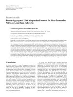
Figure 3.37 The major companies/research groups involved in the activities to develop 3- and 4G
mobile communication systems in China.
seriously involved with the TD-SCDMA platform development. It is clear that the company considers
TD-SCDMA technology to be a vital 3G solution with great opportunity for success. Siemens has
noticeably lead other foreign competitors in TD-SCDMA system development. Currently, Siemens
has invested a large amount in TD-SCDMA R&D facilities in China, where it has recruited sev-
eral hundred research personnel working in the TD-SCDMA system. Several Korean companies and
institutions, such as Samsung and ETRI, have also expressed a keen interest in TD-SCDMA systems
development. In 2001, CATT also sent a large delegation to Taiwan to seek possible collaboration
with Taiwanese companies in chip set design, silicon wafer fabrication support, and so on.
Since China has the largest number of GSM subscribers in the world, the technical similarity
(especially in mobile CNs) between TD-SCDMA and GSM gives an advantage to those GSM oper-
ators who upgraded their networks into TD-SCDMA at a relatively low cost, in comparison with
opting for other 3G standards. CATT estimates that the saving in the upgrading cost can be as much
as 30%. Currently, both CATT and Siemens are developing dual-mode and dual-band terminals for
use in GSM and TD-SCDMA networks to suit the great needs in the transition period from 2- to 3G
systems in China, as well as other regions, where the TD-SCDMA will be selected as a 3G solution
for the replacement of its legacy GSM networks.
3G MOBILE CELLULAR TECHNOLOGIES 193
3.3.2 Overview of TD-SCDMA
As its name suggested, the TD-SCDMA standard carries two important characteristic features: one
is to adopt the Time Division Duplex (TDD) mode for uplink and downlink traffic separation. The
other is to use synchronous CDMA technology, as the character “S” in front of “CDMA” implies.
The use of TDD in the TD-SCDMA standard offers several attractions. First, the agility in
spectrum allocation for mobile services is a great advantage for the TDD operation mode, in com-
parison with FDD, which requires pair-wise spectrum allocation for uplink and downlink, causing
a big burden for the countries where spectrum resources have already become very tight, such as
the United States and Japan. Second, the use of the same carrier in both up- and downlinks helps
with the implementation of smart antenna and other technologies that rely on identical propagation
characteristics in both up- and downlinks. Third, TD-SCDMA facilitates asymmetric traffic support
in up- and downlinks, associated with the increasing popularity of Internet services. The transmission
rates in the two links can be dynamically adjusted according to specific traffic requirements, so that
the overall bandwidth utilization efficiency can be maximized. Fourth, the TDD technology used in
TD-SCDMA is attributed to the lower implementation cost of RF transceivers, which do not require a
high isolation for the transmission and the reception of multiplexing as needed in an FDD transceiver;
therefore an entire TD-SCDMA RF transceiver can be integrated into a single IC chip. On the con-
trary, an FDD transceiver requires two independent sets of RF electronics for uplink and downlink
signal loops. The cost saving can be as much as 20–50% if compared with FDD solutions. Because
of the aforementioned merits, some people expected the TDD technology to be a vital solution for
4G mobile communications, especially for the small coverage areas.
However, it is to be also noted that the use of the TDD operation in TD-SCDMA bears some
technical limitations, if compared to the FDD mode. The relatively high peak-to-average power
(PTAP) ratio is one problem. Because a CDMA transceiver is required to work in a good linearity, a
relatively high PTAP ratio will limit the effective transmission range and consequently, the coverage
area of a cell. Nevertheless, the TD-SCDMA’s PTAP ratio is 10 dB less than that of the UTRA-
TDD WCDMA proposal. Also, the discontinuity of slotted signal transmissions in the TDD mode
also reduces its capability to mitigate fast fading and the Doppler effect in mobile channels, thus
limiting the highest terminal mobility supported by the TDD systems. Fortunately, the highest mobility
supportable by TD-SCDMA can be increased to 250 km/h with the help of antenna beam-forming
and joint detection algorithms, which is comparable to the specification of the WCDMA standard,
which is less than 300 km/h. It was recently revealed in a simulation report released by CATT that
the smart antenna base station can adopt an 8-element circular array with a single-antenna mobile
unit. The results showed a satisfactory performance for a vehicle mobility as high as 250 km/h.
The comparison of fundamental operational parameters of CATT TD-SCDMA, UMTS WCDMA,
and TIA CDMA2000 standards is given in Table 3.24. We also provide a comparison between the
ETSI UTRA-TDD system and the TD-SCDMA in Table 3.25, where the similarities and differences
between the two can be seen. Because of the limits to the space in this book, we should mainly
concern ourselves with the physical layer architecture of TD-SCDMA and we will not address the
upper layer issues of the standard.
3.3.3 Frame Structure
TD-SCDMA combines both TDMA and CDMA techniques in one system, and the channelization in
TD-SCDMA is performed by both time slots and signature codes to differentiate mobile terminals
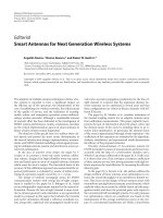
in a cell. The frame structure of TD-SCDMA is shown in Figure 3.38, where the hierarchy of four
194 3G MOBILE CELLULAR TECHNOLOGIES
Table 3.24 The comparison of the physical layer major operational parameters of TD-SCDMA,
WCDMA, and cdma2000 standards
cdma2000 WCDMA TD-SCDMA
Multiple access DS-CDMA/MC-
CDMA
DS-CDMA TDMA/DS-CDMA
CLPC 800 Hz 1600 Hz 200 Hz
PCSS 0.25 1.5 dB 0.25, 0.5, 1.0 dB 1, 2, 3 dB
Channel coding Conv./Turbo Conv./RS/Turbo Conv./Turbo
Spreading code DL: Walsh, UL: M-ary
Walsh mapping
OVSF OVSF
VSF 4···256 4···256 1···16
Carrier 2 GHz 2 GHz 2 GHz
Modulation DL: QPSK, UL:
BPSK
DL: QPSK, UL:
BPSK
QPSK, 8PSK(2 Mbps)
Bandwidth 1.25*2/3.75*2 MHz 5*2 MHz 1.6 MHz
UL-DL spectrum paired paired unpaired
Chip rate 1.2288/3.6864 Mcps 3.84 Mcps 1.28 Mcps
Framelength 20ms,5ms 10ms 10ms
Interleaving periods 5/20/40/80 ms 10/20/40/80 ms 10/20/40/80 ms
Maximum data rate 2.4 Mbps 2 Mbps (low mobility) 2 Mbps
Pilot structure DL: CCMP, UL:
DTMP
DL: DTMP, UL:
DTMP
CCMP
Detection PSBC PCBC PSBC
Inter-BS timing Sync. Async./Sync. Sync.
CCMP: common channel multiplexing
pilot
DTMP: dedicated time
multiplexing pilot
VSF: Variable spreading
factor
CLPC: Close-loop power control PCSS: Power control
step size
DL: downlink
PSBC: Pilot symbol-based coherent PCBC: Pilot channel-
based coherent
UL: upper-link
Table 3.25 The comparison of the physical layer major operational parameters between TD-SCDMA
and UTRA-TDD
UTRA-TDD TD-SCDMA
Bandwidth 5 MHz 1.6 MHz
Chip rate per carrier 3.84 Mcps 1.28 Mcps
Spreading DS, SF = 1/2/4/8/16 DS, SF = 1/2/4/8/16
Channel coding Convol. or Turbo coding Convol. or Turbo coding
No. of time slots/subframe 15*2 7*2
Burst structure Midamble Midamble
Frame length Super frame = 720 ms/Radio
frame = 10 ms
Super frame = 720 ms/Radio
frame = 10 ms
No. of channels/time slot 8 16
No. of channels/Carrier 8 ∗ 7 = 56 16 ∗ 3 = 48
Spectral efficiency 0.662 Mcps/MHz 1.232 Mcps/MHz
3G MOBILE CELLULAR TECHNOLOGIES 195
different layers of the frame structure, superframe, radio frame, subframe and time slot, are depicted.
A subframe (5 ms) consists of seven normal time slots and three special time slots, where TS0 is
reserved for downlink and TS1 is for uplink only; whereas the remaining time slots (TS2 to TS6)
should form two groups; the first group (whose size can vary from 0 to 5) is for uplink and the
second group (whose size can vary from 5 to 0) is for downlink. The size ratio of the two groups can
take 0/5, 1/4, 2/3, 3/2, 4/1 and 5/0 to suit a particular traffic requirement. The agility in the support
of asymmetric traffic is a very attractive feature of TD-SCDMA, which is of particular importance
for the Internet and multimedia services required in 3G applications. The other three special time
slots are the downlink pilot (DwPTS), guard period (GP) and uplink pilot (UpPTS) respectively.
DwPTS and UpPTS are used as SCH (Synchronization Channel) for downlink and uplink respec-
tively, which should be encoded by different PN codes to distinguish different base stations and
mobiles respectively.
A time slot can exactly fit a burst, which consists of two data parts separated by a midamble
part and followed by a guard period, as shown in Figure 3.38. Multiple bursts can be sent in the
same time slot, where the data parts of those bursts should be encoded by up to 16 different OVSF
channelization codes, whose spreading factor (SF) is fixed at 16 for downlinks and can vary from 1
to 16 for uplinks. However, each mobile can send up to two OVSF channelization codes in the same
slot to form multicode transmission. The data parts of the burst should always be spread by using
OVSF codes and scrambling codes, combined to distinguish the mobile and base station respectively.
The information about the OVSF codes can be found in Subsection 3.2.8.
A TD-SCDMA physical channel is uniquely defined by frequency, channelization code, time slot,
and radio frame allocation jointly.
Super Frame (720 ms)
Radio Frame (10 ms)
Subframe No. 2i
Subframe (5 ms)
Subframe No. 2i + 1
Data (352 chips) Midamble (144 chips) Data (352 chips)
Time slot (0.675 ms)
Time slot (0.675 ms)
DwPTS(75us)
TS0 TS3 TS4 TS5 TS6TS2TS1
UpPTS(125us)
G(75us/96 chips)
16 chips
g
gg
128 chips 32 chips32 chips 64 chips
SYNC_ULSYNC_DL
Frame No. i
Frame No. i + 1
Figure 3.38 The four-layered frame hierarchy in TD-SCDMA standard. TS: time slot; DwPTS:
downlink pilot time slot; UpPTS: uplink pilot time slot; G/g: guard period. TS0 is reserved for
downlink and TS1 is for uplink only; while the remaining time slots (TS2 to TS6) can form two
groups, the first group (which can consist of 0 slot) is for uplink and the second group is for downlink
in order to suit a particular traffic requirement.
196 3G MOBILE CELLULAR TECHNOLOGIES
3.3.4 Smart Antenna
Smart antenna techniques have been integrated into the TD-SCDMA standard as they are an indis-
pensable part of the standard. A smart antenna system is composed of an array of multiple antenna
elements and coherent transceivers with an advanced digital signal processing unit. Instead of a single
fixed beam pattern from a traditional antenna, the smart antenna can dynamically generate multiple
beam patterns, each of which is pointed to a particular mobile; such beam patterns can adapt to follow
any mobile adaptively. As a result, cochannel interference can be greatly reduced to enhance recep-
tion sensitivity, and therefore the capacity of the whole system. It can also effectively incorporate
multipath components to combat multipath fading. The 5 ms subframe structure in TD-SCDMA is
designed for the application of the smart antenna. More specifically, it implements fast beam-forming
to follow the time variation of mobile channels. The 5 ms subframe length is a compromise by taking
into account both the number of time slots and switching speed of the RF components used in a
transmitter. It was reported that an 8-element circular array antenna with a diameter of 25 cm has
been considered for use in TD-SCDMA base stations. If compared to an omni-directional antenna,
there is an 8 dB gain obtainable by using such a circular array antenna. The TDD operation in TD-
SCDMA ensures an ideally symmetric beam pattern for both the transmission of and the reception
at the same base station, which improves channel estimation and beam-forming accuracy due to the
same propagation characteristic in the uplink and downlink channels.
As mentioned above, a burst contains a 144-chip midamble, which functions as a training sequence
for beam-forming carried out in the smart antenna system. The midamble is encoded by basic
midamble codes. There are totally 128 different basic midamble codes of length 128 for the whole
system, which are allocated into 32 code groups with four codes in each code group. The choice of
code group is determined by base stations, such that four basic midamble codes are known to base
stations and mobiles. The midambles of different users active in the same cell and the same time slot
are cyclically shifted versions of one single basic midamble code.
Because of the provision for the use of transmit diversity, TD-SCDMA can also take full advantage
of space-time coded signaling to further enhance the capacity of the system.
3.3.5 Adaptive Beam Patterns
There are two categories of transport channels in TD-SCDMA, which are Dedicated Transport Chan-
nels (DTC) and CTCs. The DTC is further divided into DCH and ODMA Dedicated Transport
Channels (ODCH); the CTC is divided into six subtypes, as shown in Table 3.26.
It is specified in TD-SCDMA downlink transmissions from a base station that all CTCs (such as
SCH, Pilot, BCH, PCH etc.) which usually carry the shared information of the network use omni-
directional beam patterns to send their signals; all DTCs, which carry dedicated user or control
signals, use directional beam patterns with the help of smart antenna technology. On the other hand,
all the receiving channels in a base station should also use directional beam patterns to suppress
the interferences from other unwanted transmissions. The use of different beam patterns for different
transport channels in the TD-SCDMA system can effectively increase the utilization efficiency of
transmission power from base stations and reduce cochannel interference in the cell, which contributes
to the increase of cell capacity.
The introduction of beam-forming in all receiving channels can also facilitate mobile location
positioning, based on the numerous new services (otherwise impossible) that can be added in a mobile
cellular system.
3.3.6 Up-Link Synchronization Control
Another critical technique used in the TD-SCDMA is the synchronous CDMA transmission in down-
link and uplink, both of which use OVSF codes for channelization due to its ideal orthogonality.
3G MOBILE CELLULAR TECHNOLOGIES 197
Table 3.26 Two types of transport channels in TD-SCDMA
Common Transport Channels (CTC)* Dedicated Transport Channels (DTC)**
Broadcast Channel (BCH) Dedicated Channels (DCH)
Paging Channel (PCH) ODMA Dedicated Transport Channels (ODCH)
Forward Access Channel (FACH)
Random Access Channel (RACH)
Uplink Shared Channel (USCH)
Downlink Shared Channel (DSCH)
* CTC carries shared information of network
** DTC carries dedicated user/control signals between UE & network
In order to achieve the synchronization in the uplink, the TD-SCDMA introduces open-loop and
close-loop synchronization control in its signaling design.
To pave the way for the successful application of orthogonal codes in asynchronous uplink
channels, uplink synchronization control, which has been considered an option in the UMTS UTRA
[425] and WCDMA [431] standards is necessary. However, real workable schemes have been solely
implemented in the TD-SCDMA standard [432, 433] as an important part of the system architecture.
Similar to the power control algorithm, there are two sectors of uplink synchronization control: the
open-loop sector and the closed-loop sector, which ought to work jointly to achieve an accurate
synchronization, up to 1/8 chip, as specified in the TD-SCDMA standard [432, 433]. With the help
of such an accurate uplink synchronization control algorithm, the transmission channels in the uplink
have been converted into quasi-synchronous ones, effectively enhancing the detection efficiency in
the uplink channel of a CDMA system, which is often a bottleneck in the whole air-link section.
During a call set-up procedure, a mobile should first establish downlink synchronization with the
base station by looking for DwPTS, after which it will initiate the uplink synchronization procedure.
In the beginning, a mobile can estimate the propagation delay from a base by the received power
level of DwPTS. Its first transmission in uplink is performed in the UpPTS time slot to reduce inter-
ference in the normal time slots. The timing used for the SYNC
UL burst is set according to the
received power level of DwPTS. This executes the open-loop synchronization. At the detection of
the SYNC
UL burst, the base station will evaluate the received power level and timing, and reply by
sending the adjustment information to the mobile in order to modify its uplink transmission timing
and power level in the next transmission.
To maintain the uplink synchronization, the midamble field of each uplink burst will be used. In
each uplink time slot, the midamble from each mobile in the cell is distinct. The base station can
estimate the power level and timing by measuring the midamble field from each mobile in the same
time slot. In the next available downlink time slot, the base station will signal the Synchronization
Shift (SS) and the Power Control (PC) commands, which occupy part of the midamble field, to enable
the mobile to properly adjust its transmission timing and power level, respectively. The uplink syn-
chronization can be checked once per TDD subframe and the step size in the uplink synchronization
can be adapted from 1/8 chip to 1 chip duration, which is sufficiently accurate in order to maintain
the orthogonality of OVSF codes from different mobiles. Figure 3.39 shows the flow-chart of the
open/close-loop synchronization algorithm used by TD-SCDMA.
The detailed procedure of the uplink synchronization control algorithm can be explained as fol-
lows. During the cell search procedure in a TD-SCDMA system, a mobile will capture the information
in downlink broadcasting slots to know the power level of a transmitted signal from a BS, based
on which the mobile can roughly estimate the distance from the BS using a simple free-space prop-
agation law to complete the open-loop uplink synchronous control stage. With this knowledge, the
198 3G MOBILE CELLULAR TECHNOLOGIES
Start
Mobile Power On
Cell search
using SYNC_DL
to acquire DwPTS
Establish the downlink
synchronization
Use SYNC_UL to
transmit the UpPTS
according to the
received power level of
DwPTS and/or P-CCPCH
BT will evaluate
the received power
level & timing
Within the 4 sub-
frames BT will
send the adjustment
information to mobile
The uplink
synchronization is
established
Maintenance of
uplink
synchronization
The BT will estimate the
timing shift by measuring the
midamble field of each mobile in the
same time slot.
BT will signal the
Synchronization Shift (SS) to
enable the mobile to adjust its Tx
timing.
Synchronized
Unsynchronized
Figure 3.39 The flow-chart diagram of closed and open loops synchronization control used by TD-
SCDMA for both uplink and downlink, from which it is seen that the downlink synchronization is
established before the uplink synchronization.
3G MOBILE CELLULAR TECHNOLOGIES 199
mobile will send a testing burst in a special slot dedicated only for uplink testing bursts, called an
UpPTS slot. If this testing burst has fallen within the search-window at the BS receiver, the testing
burst will be successfully received and the BS will know if the timing for the mobile to send its burst
is correct or not. If not, the BS should send SS instructions in the next downlink slots to ask the
mobile to adjust its transmission timing to complete the closed-loop uplink synchronization control
cycle. It is specified in the TD-SCDMA standard that the initial uplink synchronization procedure
has to be finished within four subframes, followed by the uplink synchronization tracking process. A
detailed illustration of both the open-loop and closed-loop uplink synchronization control algorithm
implemented by TD-SCDMA is shown in Figure 3.40, where a scenario with three mobiles commu-
nicating with a BS is illustrated with UE3 being the mobile of interest, which wants to proceed with
the uplink synchronization with the BS; furthermore, UE1 and UE2 are the mobiles that have already
established communication links with the BS.
Obviously, the need for uplink synchronization control in the TD-SCDMA system is because
of its use of OVSF codes, which are orthogonal codes, and perform poorly in asynchronous uplink
channels due to the fact that the characteristics of their ACFs and CCFs in an asynchronous channel
are very bad. However, it is still natural for us to question the justification of introducing such a
complicated uplink synchronization control system simply for the application of orthogonal OVSF
codes in uplink channels. Why do we not think about other better solutions, such as using some
new spreading codes with an inherent isotropic or symmetrical performance? This indeed opens an
interesting issue, which should be discussed in Chapter 7.
3.3.7 Intercell Synchronization
The TD-SCDMA standard adopts a technique used to achieve synchronization among neighboring
base stations in order to optimize system capacity and to perform cell search in a handover procedure.
A typical example for such a need is a scenario for coordinated operations with overlapping coverage
areas of the cells, or there is contiguous coverage for a certain area. In fact, a TDD system requires
such intercell synchronization, especially in the handover procedure, where a mobile will communicate
with two or three base stations simultaneously. In such a scenario, a common clock source is needed
to maintain the intercell synchronization. The synchronization between base stations and between
cells is very important for the TDD mode to avoid interferences from nearby cells.
In the TD-SCDMA standard there are several possible ways to achieve the synchronous trans-
mission among neighboring cells. The first way is to achieve the synchronization via the air interface,
in which a special burst, Network Synchronous Burst, is employed. This burst should be sent on a
predetermined time slot at regular intervals. The base stations involved should adjust their respective
downlink signals timing in accordance with the network synchronous bursts. The second alternative
way is to use other cell’s DwPTS as a timing basis for the synchronous transmissions of base stations
involved. Yet another way is to simply use a GPS as a common clock to synchronize the base stations.
It is likely that the first generation TD-SCDMA network will work on a GPS in order to achieve the
intercell synchronization to let the base stations have the same timing reference for transmitting and
receiving. The accuracy for such intercell synchronization is required at about 5 µs.
With the intercell synchronization, the transmission time for each cell can be determined in
network planing and controlled by the TD-SCDMA CN. The time offset in nearby cells is separated
by at least one fixed time delay, which should be approximately 80% of the transmission time between
two neighboring cells.
3.3.8 Baton Handover
Baton Handover is another salient feature offered by the TD-SCDMA standard, which is used to take
advantage of both hard handoff and SHO and is particularly suited for the TDD mode operation.
200 3G MOBILE CELLULAR TECHNOLOGIES
The distance between UE
and the BS is
d1<d2< d3.
Signals at Base Station
Signals at Mobiles
UE1
UE3
UE2
UE2
UE3
UE1
UE2
UE3
UE1
UE2
UE3
UE1
UE2
UE3
UE1
Ts0
Ts0
Ts0
Ts0
Ts0
Ts1
Ts1
Ts1
Ts1
Ts2
Ts2
Ts2
Ts2
GP
GP
BS
BS
BS
BS
BS
GP
GP
t1
t0
t0
t0 t7'
t3 t6t6'
t0
t0 t1 t3 t2 t5 t6' t6 t4 t7' t7
t7'
t7
t2
t3
t1
t2
t3
t4
t5
t1
t2
t4
t5
t3 t6
t1
t2
t4
t5
t6'
UpPTS
UpPTS
UpPTS
UpPTS
DwPTS
DwPTS
Ts0 Ts1 Ts2
GP
UpPTSDwPTS
Ts0 Ts1 Ts2
GP
UpPTSDwPTS
Ts0 Ts1 Ts2
GP
UpPTS
DwPTS
Ts0
GP
UpPTSDwPTS
Ts0 Ts1 Ts2
GP
UpPTSDwPTS
Ts0 Ts1 Ts2
GP
UpPTSDwPTS
Ts0
GP
UpPTSDwPTS
Ts0 Ts1 Ts2
Ts1 Ts2
GP
UpPTSDwPTS
Ts0 Ts1 Ts2
GP
UpPTSDwPTS
Ts0
GP
UpPTSDwPTS
Ts0
GP
UpPTSDwPTS
Ts0 Ts1 Ts2
GP
UpPTSDwPTS
Ts0 Ts1 Ts2
GP
UpPTSDwPTS
Ts0 Ts1 Ts2
GP
UpPTSDwPTS
Ts0 Ts1 Ts2
GP
UpPTSDwPTS
Ts0 Ts1 Ts2
GP
UpPTSDwPTS
Ts0
GP
UpPTSDwPTS
DwPTS
Ts0 Ts1
Ts2
GP
UpPTSDwPTS
DwPTS
DwPTS
BS
d3
d
1
d
2
UE3 adjusts its timing
for sending UpPTS to
establish the uplink
synchronization.
UE3 first transmits signal in
UpPTS and determines the
transmission timing
according to the recieved
power level of DwPTS and/or
P-CCPCH.
After the cell search
procedure the new user
UE3 uses the SYNC_DL(in
DwPTS) to acquire DwPTS
synchronization to the BS.
Ts0 & Dwpts are for the
Downlink channel;
Ts1, Ts2, UpPTS are for the
Uplink channel.
The BS detects the UE3 in the
searching window and will
evaluate the recieved power level
and timing.
The time that UE received
the signal from the BS
t1<t3<t2
The time that UEs transmit
the signal from the BS
t5<t6'<t4
Searching
Window
Searching
Window
The BS replies UE3 by sending the adjiustment
information in the next subframe for UE3 to modify
its timing and power level for the next transmission
to establish the uplink synchronization.
Uplink Synchronization
Completed.
Schedule Diagram of Uplink Synchronization Control
Downlink channel
transmits by BS
Uplink channel
transmits by UE1
Uplink channel
transmits by UE3
UpPTS may not
be sent in normal
connection mode
Uplink channel
transmits by UE2
UE3 receives
the signal
from BS
BS transmits
the Downlink
signal
UE1 receives
the signal
from BS
UE1
transmits the
signal to BS
BS receives
the signal
from UEs
UE2 receives
the signal
from BS
UE3 transmits
the signal to
BS(unsynchr
onization)
UE2
transmits the
signal to BS
UE3
transmits the
signal to BS
BS receives
the signal
from UE3
Uplink channel
transmits by
UE3(unsynchroniz
ation)
Figure 3.40 Illustration of open-loop and close-loop uplink synchronization control algorithm speci-
fied by the TD-SCDMA standard.
3G MOBILE CELLULAR TECHNOLOGIES 201
The baton handover, similar to the procedure as the handover of a baton is in relay, is based
mainly on the user positioning capability provided by TD-SCDMA base stations using smart antenna
technology.
In an urban pedestrian environment, it may obtain wrong information of the position for a mobile
by use of a single base station because of serious multipath. Therefore, it has to be aided by cell
search, based on the report from the mobile to make a decision on which the target base station is.
The successful operation of baton handover is based on the fact that:
• the system knows the position of all mobiles;
• the system knows and determines the target cell for handover;
• the system informs the mobile about the base station in neighboring cells;
• the mobile measurement helps the system to make the final decision;
• after the cell search procedure, the mobile has already established synchronization to the base
station in the target cell.
The procedure of the baton handover supported in TD-SCDMA can be explained as follows.
Assume that BTS0 is the base station the mobile connects to earlier and BTS1 is the base station the
mobile wants to handover. First, the mobile should listen to the broadcasted information from BTS0,
which includes the data related to nearby cells including position, the operation carrier frequency,
the Tx time offset, the short code distributed, and so on. The mobile will search the nearby cells
based on the above received information. With that information the mobile is able to send relevant
information to BTS1 via some common transport channel so that BTS1 can also measure the location
of the mobile by the burst exchange between them. The handover procedure can be initiated by either
a mobile or a BTS, but the network will decide when to execute the handover. Therefore, the baton
handover is different from the soft handover that has been applied in IS-95, which makes use of
macrodiversity.
By using the baton handover concept, the system will support both intrafrequency and interfre-
quency (in the TD-SCDMA system) handovers, and give higher accuracy and a shorter handover time
period for handovers inside the TD-SCDMA system and between different systems. There are several
different handover procedures defined in TD-SCDMA, which include intrasystem and intersystem han-
dovers. The intersystem handover can be further divided into the TD-SCDMA/GSM handover and the
TD-SCDMA/UTRA-FDD handover in order to provide future cooperation among different networks,
which is extremely important especially in the initial period of TD-SCDMA network deployment
when TD-SCDMA may coexist with GSM and other possible 3G systems such as UTRA-TDD, and
so on.
3.3.9 Intercell Dynamic Channel Allocation
Channel allocation in TD-SCDMA can be made very flexible due to the use of synchronous TDD
technology. It is possible that each TD-SCDMA base station can make use of three different carriers to
occupy about 5 MHz bandwidth (each takes 1.6 MHz), which is the same as the bandwidth required
by one carrier in UTRA-TDD. On the other hand, TD-SCDMA can also operate in a mode that
each cell uses only one 1.6 MHz bandwidth and three neighboring cells can use three different
carriers. On the other hand, each TD-SCDMA time slot can support 16 simultaneous code channels
and each subframe has seven normal time slots, which can be made symmetric or asymmetric for
downlink and uplink traffic. Therefore, the physical channels in TD-SCDMA can be viewed as a
“pool,” each element of which can be uniquely determined by three indices: carrier frequency, OVSF
code and time slot. In this way, the channel allocation for each cell can be made a dynamic way in
terms of three neighboring cells to further increase the bandwidth utilization efficiency of the overall
system.
202 3G MOBILE CELLULAR TECHNOLOGIES
3.3.10 Flexibility in Network Deployment
TD-SCDMA carries many similar technical features as GSM and UTRA-TDD standards, which makes
it possible for TD-SCDMA network to be deployed in an evolutionary, rather than a revolutionary way.
It has been suggested that the TD-SCDMA network can be implemented via two phases, taking into
account the currently operating networks in many countries around the world. The initial phase can
only implement TD-SCDMA physical layer functionalities, with only some necessary modifications
to the existing GSM second and third layer core networks to make them compatible with the TD-
SCDMA upper layers requirements. Such an initial TD-SCDMA deployment can offer a maximum
of 284 kbps data transmission rate services, which is comparable to 2.5G mobile communication
system. If compared to the upgrade from GSM to WCDMA network, such an initial deployment of
TD-SCDMA can save up to 50–70% cost, as estimated by some analysts. The saving in the initial
deployment phases is significant in terms of view of business, because it greatly reduces the risk of the
investment of service providers and paves the way for future network evolution toward full-functional
3G network. The second phase involves using full-functional TD-SCDMA physical layers and the
second and third layers should use 3GPP compatible upper layers standard to meet the full functions
required by IMT-2000. The maximum transmission rate can reach 2 Mbps, which is compatible with
3G requirement.
On the other hand, TD-SCDMA can also support the coexisting operation of different mobile
networks, such as GSM and UTRA-TDD standards, which has been discussed in aforementioned
sections on handover procedures across different mobile networks. Therefore, TD-SCDMA is par-
ticularly attractive for homogenous evolution from existing 2G toward 3G mobile networks at a
relatively low upgrading cost and investment risk.
3.3.11 Technical Limitations of TD-SCDMA
There are several technical limitations in TD-SCDMA. Some of them stem from the TD-SCDMA
system itself, and the other from TDD systems in general.
It is to be noted from Tables 3.24 and 3.25 that TD-SCDMA uses SF = 1 at a data rate of 2 Mbps,
implying that no processing gain will be available in the highest transmission rate scenario. In such
a case, multipath diversity gain will not be available, and the system should rely on other techniques
to enhance the detection efficiency.
The use of OVSF codes in TD-SCDMA poses another problem for low-efficient and complex
rate-matching algorithm for multimedia applications. The change of SF in OVSF codes must be
made multiples of two, and as a result it is impossible to support arbitrary transmission rates to fit a
particular data rate.
The application of uplink synchronization control also increases the complexity of the system, in
both handsets and base stations. The success of the Baton Handover relies heavily on the accuracy in
mobile positioning techniques provided by smart antenna, making it necessary to handle all handovers
in a centralized way to increase overall networking traffic.
3.3.12 Global Impact of TD-SCDMA
At the time this book is written, China has not yet formally decided what standard it will adopt as a
major 3G technology. However, there have been some signs that China is likely to support its own
3G standard and encourage its services providers to adopt them. If so, there will be some foreseeable
impact to the world mobile communication market due to its sheer market size. The foreign mobile
manufacturers should be very careful with China’s 3G licensing process, which has not yet been
decided. Table 3.27 shows the different natures of telecommunication markets in the United States,
Europe, Japan, and China.
3G MOBILE CELLULAR TECHNOLOGIES 203
Table 3.27 Driving forces behind mobile
communication technology development
in the United States, Europe, Japan, and
China
Region Driven mainly by
United States Market
Europe Technology
Japan Mobile Operators/Market
China Government/Market
Technically speaking, TD-SCDMA is probably one of the most cost-effective solutions for the
upgradation of existing GSM networks to 3G systems due to its unique technical feature. In this
sense, the possible market for the TD-SCDMA system exists, simply because of the great success of
GSM networks in the world. Therefore, the TD-SCDMA standard is in principle suitable not only for
China, but also for any other regions where GSM is operating. Thus, the possible market competition
with WCDMA (for both its TDD and FDD schemes) can be expected.
Since the submission of the TD-SCDMA proposal to ITU in 1998, China has taken a critical
path in developing its own national 3G standard, which can be ready within years. China has become
the largest single mobile communications market in the world and its great potential for 3G wireless
applications has attracted all the major telecommunication companies in the world, especially after
China’s entry into the WTO. China’s market is now open to foreign investment in terms of mobile
communication equipments and services and is ready to market its own 3G technology to the world.
To deal with the emergence of ever severe competition, China wants to promote its own 3G standard
to save the cost for purchasing foreign IPRs and technologies and to eventually access the world-
wide mobile market. The TD-SCDMA standard adopts numerous advanced technologies and offers
a relatively cost-effective way to upgrade existing GSM networks to 3G CNs. Therefore, it is an
attractive 3G technology, not only for China but also for the world. It can substantially reduce the
investment risk, which is the most serious concern to almost all the existing 2G service providers
with 3G licences in their hands. The impact of TD-SCDMA should never be under-estimated.
More information about the TD-SCDMA can be found in [432–439].
4
Wireless Data Networks
Why create a wireless network? The best-selling feature of most wireless technology is portability
[453]. If every device in a network is joined wirelessly, then users benefit not only from the mobility
of their telephones and notebook computers: They can interface a camera with a PC from the couch
instead of sitting at their desks, where their cameras are connected to their PCs by some sort of
cable or plug, and they can rearrange office equipment by moving devices, like printers or scanners,
anywhere within range, without stringing new wires (and drilling new holes in the walls).
4.1 IEEE 802.11 Standards for Wireless Networks
The Institute of Electrical and Electronics Engineers (IEEE) develops and maintains technological
standards based on the recommendations of individuals with expertise in the technology being stan-
dardized. Scientists, manufacturers, and end-users provide input to the institute, which comes to
a consensus about the standards suitable for a particular technology. Use of an IEEE Standard is
wholly voluntary and the existence of an IEEE Standard does not imply that there are no other ways
to produce, test, measure, purchase, market, or provide other goods and services related to the scope
of the IEEE Standard [452]. Research scientists, manufacturers, and end-users all benefit from the
shared specifications contained in the standards. When everyone uses the standard, customers can use
equipment from different manufacturers with no incompatibilities.
The IEEE 802 set of standards has to do with the physical layer (PHY) and data link layers of local
and metropolitan area networks (LANs and MANs). These are the bottom two layers in the ISO/OSI
networking model, far removed from the application layer, and are concerned with data transmission
(and reception) between computers in LANs and MANs. The IEEE has split the data link layer into
two different sublayers: logical link control (LLC) and media access control (MAC) (see Figure 4.1).
The IEEE LLC protocol concerns the logical address, control information, and data portions of an
HDLC (high-level data link control) frame, while the MAC protocols deal with synchronization, error
control (EC), and physical addresses. MAC protocols are specific to the LAN using them (Ethernet,
Token Ring, Token Bus, etc.) [455].
The IEEE 802.3 standards are concerned with Ethernet (wired) communications. Originally, they
supported 10-Mbps data rates, but as network terminals became faster and thus capable of running
multimedia applications, and as the need to share high-speed servers among LANs became widespread,
faster data rates were included in the standards. They were updated in the mid-1990s to include “fast
Ethernet” transmission rates of 100 Mbps, and in the late 1990s the Gigabit Ethernet was standardized
Next Generation Wireless Systems and Networks Hsiao-Hwa Chen and Mohsen Guizani
2006 John Wiley & Sons, Ltd
206 WIRELESS DATA NETWORKS
Other layers
Network
Logical link control
(LLC)
Media access control
(MAC)
Physical
Other layers
Network
Data link
Physical
Project 802 OSI Model
Figure 4.1 MAC and LLC split [455].
under 802.3 [454]. Experts attest that the two major driving forces of this industry have always been
the ease of installation and increase of data rate, the two important characteristics of Fast Ethernet
and Gigabit Ethernet. Thus, Ethernet dominated over other 802.3 LAN IEEE standards (the so-called
Token Ring and Token Bus).
The 802.4 and 802.5 standards concern the PHY and MAC layers for Token Bus and Token Ring
topologies, respectively. IEEE’s 802.6 standards address the needs of MANs [454]. The 802.11 family
of standards is devoted to the requirements of the bottom two ISO layers in wireless networks (wireless
local-area networks (WLANs)). A complete list of the rest of the standards is given in Table 4.1.
When developing the standards for wireless networks, the IEEE observed the radio frequency
regulations of the US Federal Communications Commission (FCC), since radio waves were the
transmission medium of choice for wireless networking. In 1985, the FCC designated certain portions
of the radio frequency spectrum for industrial, scientific, and medical use, and these became known
as the ISM bands; they are: (1) 902–928 MHz, a bandwidth of 26 MHz; (2) 2.4–2.4835 GHz, a
bandwidth of 83.5 MHz, commonly called the 2.4-GHz band; and (3) 5.725–5.850 GHz, a bandwidth
of 125 MHz, commonly called the 5-GHz band.
Within certain guidelines, the FCC’s regulations allow users to operate radios inside these bands
without an FCC licence, an obvious boon for the developers of wireless network technology (and for
the users who do not have to obtain a licence to operate their cell phones) [453].
The 802.11 standards have evolved over time, and presently six methods for wireless data trans-
mission are defined in the 802.11 standards. Each means of transmission represents its own PHY
within 802.11. The first IEEE 802.11 standards were completed in 1997, and defined three of these
PHY for 1- and 2-Mbps data rates. An overview of these PHY is provided in Table 4.2 and also
explained as follows:
• The Direct-Sequence Spread Spectrum (DSSS)
1
PHY uses the 2.4-GHz band and can transmit
data at 1 or 2 Mbps. It was first used for military communications. To prevent jamming,
and, to a lesser extent, eavesdropping, radios that use DSSS transmit their signals across the
entire available ISM band at very low power. This prevents interference from narrowband
signals (jammers or others) and lessens the likelihood of transmission errors. Eavesdroppers
may interpret these signals as background noise [452, 453].
• The Frequency Hopping Spread Spectrum (FHSS) PHY also uses the 2.4-GHz band for trans-
mission at 1 or 2 Mbps, and also originated in military applications. Two communicating radios
1
More detailed discussions on DS and other station services (SS) techniques can be found in Section 2.2.
WIRELESS DATA NETWORKS 207
Table 4.1 802.11 standards list [486]
802.1 Higher-layer LAN protocols
802.2 Logical link control
802.3 Ethernet (wired)
802.4 Token Bus
802.5 Token Ring
802.6 MAN
802.7 Broadband
802.8 Fiber optic
802.9 Isochronous LAN
802.10 LAN/MAN Security
802.11a Wireless LAN: 5-GHz band
802.11b Wireless LAN: 2.4-GHz band
802.11c Wireless LAN: higher layers
802.11d Wireless LAN: MAC
802.11e Wireless LAN: MAC
802.11f Higher layers
802.11g Wireless LAN: higher rate 2.4-GHz band
802.11h Wireless LAN: MAC
802.11i Wireless LAN: MAC
802.12 Demand priority
802.13 Not used
802.14 Cable modem
802.15 Wireless PAN
802.16 Broadband wireless access
802.17 Resilient packet ring
802.18 Radio regulations
802.19 Coexistence
802.20 Mobile broadband wireless access
Table 4.2 802.11 PHY layers
DSSS 2.4 GHz 1 or 2 Mbps
FHSS 2.4 GHz 1 or 2 Mbps
DFIR 850 to 950 nm (infrared) None implemented
COFDM 5 GHz 54 Mbps
HR/DSSS 2.4 GHz 5.5 or 11 Mbps
OFDM 2.4 GHz 54 Mbps
using FHSS change frequencies according to a predetermined pseudorandom pattern, and only
remain on a given frequency for a split second (FCC regulations require the frequency hops to
take place in 400 ms or less). This technique minimizes the chances that more than one radio
device will be transmitting on the same frequency at the same time. If a sender happens to
detect interference from another radio at a particular frequency, it retransmits its data after the
next hop to a new frequency [453]. FHSS was phased out of 802.11 in the 802.11b standards.
• The Diffused Infrared (DFIR) PHY uses near-visible light in the 850-nm to 950-nm range for
signaling [452]. However, unlike infrared (IR) TV remote controls that need a line of sight to
208 WIRELESS DATA NETWORKS
work, devices that follow the 802.11 DFIR standards do not need to be aimed at one another,
permitting the construction of a true LAN [452]. But, there are no wireless networking products
currently available that implement this PHY [453]. One potential source of interference when
using this technology would be a human being walking between a PC and its printer when they
were trying to communicate.
• A fourth 802.11 PHY is defined by IEEE’s 802.11a standards: The Coded Orthogonal Fre-
quency Division Multiplexing (COFDM) layer is capable of transmitting data at 54 Mbps by
using the broader 5-GHz band. However, FCC regulations limit the transmission power used
at these higher frequencies, and thus it reduces the distance higher-frequency transmissions
can travel. For these reasons, radios that use COFDM technology must be closer together than
those using the other PHY introduced above. The obvious benefit of COFDM is speed. The
IEEE 802.11a standards are further discussed in Section 4.2.
• The IEEE 802.11b standards cover the fifth PHY, the High-Rate Direct-Sequence Spread Spec-
trum (HR/DSSS) layer. Using this layer, data can be transmitted at 5.5 or 11 Mbps, rivaling the
standard Ethernet rate of 10 Mbps, and it has become the most widely used IEEE 802.11 PHY
despite its recent entry onto the scene in 1999. HR/DSSS technology is an extension of DSSS
technology and is designed to be backward compatible with its predecessor (both operate in the
2.4-MHz band) [453]. Further discussion on the 802.11b standards is presented in Section 4.1.7.
• The sixth 802.11 PHY is detailed in the IEEE 802.11g standards and is backward compatible
with 802.11b. The Orthogonal Frequency Division Multiplexing (OFDM) PHY allows 54 Mbps
data rates in the 2.4-MHz band. The speed of transmission under OFDM and COFDM is suf-
ficient to carry voice and image data fast enough for most users. More on the IEEE 802.11g
standards is given in Section 4.1.8.
4.1.1 Fundamentals of IEEE 802.11 Standards
Wireless LAN systems [472, 473, 481, 489] are different from wired LANs for a variety of reasons.
The addressing schemes (and hence the contents of frames) must take into account the mobility of
the network nodes, the PHY have to cope with the lower range and reliability of wireless media
(WM), and the MAC sublayers have to ensure that these adjustments are presented to every higher
layer (from the logical link layer on up) as a “generic” 802.11 LAN would. While one can easily
draw the architecture of a wired LAN, for wireless PHYs, well-defined coverage areas simply do not
exist. Propagation characteristics are dynamic and unpredictable (see Figure 4.2). Small changes in
position or direction may result in dramatic differences in signal strength. Similar effects occur whether
a station (STA) is stationary or mobile (as moving objects may impact station-to-station propagation).
The shapes used in IEEE WLAN architecture drawings are there as a matter of convenience. In
reality, the boundaries of WLANs are not well-defined from one moment to the next, mostly due to
the mobility of the nodes (the addressable units of the WLAN).
In IEEE 802.11, the addressable unit is a STA. The STA is a message destination, but not (in
general) a fixed location, as would be the case in a wired LAN. MAC frames are adjusted to take this
change into account. The IEEE makes these observations about 802.11 PHYs, noting that they (a) Use
a medium that has neither absolute nor readily observable boundaries outside of which stations with
conformal PHY transceivers are known to be unable to receive network frames; (b) Are unprotected
from outside signals; (c) Communicate over a medium significantly less reliable than wired PHYs;
(d) Have dynamic topologies; (e) Lack full connectivity, and therefore the assumption normally made
that every STA can hear every other STA is invalid (i.e., STAs may be “hidden” from each other);
(f) Have time-varying and asymmetric propagation properties [452].
WIRELESS DATA NETWORKS 209
DSS
DSS
SS
SS
DSS
DS
AP
AP
BSS 2
BSS 1
STA 2
STA 3
STA 4
STA 1
Portal
802.×LAN
802.11 Components
ESS
802.11 MAC/PHY
802.11 MAC/PHY
Figure 4.2 802.11 WLAN components [452].
Additionally, the specifications for the 802.11 PHYs must allow for both portable and mobile
stations. Portable stations may change location from one access time to another, but mobile stations
access the network while they are moving. Furthermore, the design of the PHYs recognizes that there
is no guarantee that a particular station will be powered up at any particular time [452].
The architectural components of an 802.11 network include STA, basic service sets (BSSs),
distribution systems (DS), WM, distribution system media (DSM), access points (AP) (also known
as base stations), extended service sets (ESS), and portals, as shown in Figure 4.2 [452].
Stations are addressable units in a network and can be clients or servers. While it is possible for
two personal computers to communicate with one another directly via a wireless connection, in a
wireless LAN a personal computer is more likely to connect with a base station (or AP) for access
to the rest of the network. Personal computers and personal digital assistants (PDAs) are the most
common types of stations in a WLAN [453].
A BSS is the fundamental set of devices in a WLAN, and can comprise as few as two stations. The
IEEE 802.11 (1999) documentation also uses the term BSS loosely to mean the coverage area within
which the member stations of the BSS may remain in communication, allowing for the notion that a
station can move “out” of its BSS, where it can no longer directly communicate with other members
of the BSS [452]. An independent basic service set (IBSS) is possible if stations can communicate
directly with one another. When an IBSS is created dynamically, for temporary use, it is referred to
as an ad hoc network. If a station is a member of the infrastructure of a BSS, it is “associated” with
the BSS by means of a distribution system service (DSS), which is discussed next. The associations
are permitted to be dynamic, since stations come into and move out of range of the BSS, and can be
turned off and back on [452].
A DS (not to be confused with a DSS) is the architectural element used to connect BSSs with
one another. The DS maps addresses to actual destinations for mobile devices in multiple BSSs. In
this type of architecture, the BSSs are not independent, but are components in a larger, extended
network. The DS uses DSM, while the BSSs use what is referred to as WM. The terms are kept
distinct because DSM and WM perform different jobs in the logical view of WLAN architecture.
However, there is no IEEE “rule” that says the media used must be different if employed as DSM
or WM. That is to say, one can use the same medium to perform both logical jobs (but, to allow
210 WIRELESS DATA NETWORKS
for flexibility, one does not have to). The documentation expressly states that the IEEE 802.11 LAN
architecture is specified independently of the physical characteristics of any specific implementation.
APs are stations that provide DS services. Since they are stations, they are addressable. APs
connect STAs with their LAN. Administrators set parameters for APs, including the name of the
wireless network, the channel used by the AP, and which Wired Equivalent Privacy (WEP) key is
employed by the network for security [453]. Wireless networks use encryption to protect transmitted
data from eavesdroppers – the data is usually sent over open airwaves – and WEP keys are one way
to facilitate encryption and decryption. (As discussed in Section 4.3, WEP technology is vulnerable
to crackers.) In short, data moves from STAs in a BSS, via an AP, to the DS, and vice versa.
When you use an AP to combine a DS, one or more BSSs, and potentially one or more LANs,
the resulting network is called an ESS [453]. The IEEE 802.11 DS and BSSs allow IEEE 802.11 to
create a wireless network of arbitrary size and complexity. The key concept is that the ESS network
appears the same to an LLC layer as an IBSS network, and mobile stations may move from one BSS
to another (within the same ESS) transparent to the LLC [452].
In an ESS, all of the following are possible. (a) The BSSs may partially overlap. This is commonly
used to arrange contiguous coverage within a physical volume. (b) The BSSs could be physically
disjointed. Logically there is no limit to the distance between BSSs. (c) The BSSs may be physically
collocated. This may be done to provide redundancy. (d) One (or more) IBSS or ESS networks may
be physically present in the same space as one (or more) ESS network(s). This may occur for a
number of reasons. Two of the most common are when an ad hoc network is operating in a location
that also has an ESS network, and when physically overlapping IEEE 802.11 networks have been set
up by different organizations [452].
The last of the logical architectural units in an IEEE WLAN is the portal, which connects a
traditional wired LAN to the 802.11 WLAN. The device acting as a portal can also act as an AP
[452]. In very simple terms, a portal is the point where a wire (or cable) from a wired LAN meets
a device on the wireless LAN that can read from the portal wire and transmit to the WLAN via its
radio (or its wireless medium of choice). Needless to say, if no device on the WLAN is connected
by wire to a wired LAN, then communication between the two networks will not take place (see
Figure 4.3).
DS
AP
AP
BSS 2
BSS 1
STA 2
STA 3
STA 4
STA 1
Portal
802.×LAN
802.11 Components
Figure 4.3 Portal connects wired LAN to WLAN [452].
WIRELESS DATA NETWORKS 211
Now that we are talking about joining wireless networks to other LANs, it is necessary to adopt
the convention that IEEE uses to portray this concept in the 802.11 standards. In the first place, the
DSS used by the joined networks do not have to be the same; in fact, IEEE 802.11 explicitly does
not specify the details of DS implementations. Instead, IEEE 802.11 specifies services. The MAC
sublayer of the WLAN utilizes these services while connecting the STAs on the network and to
protect the data they wish to exchange. The services are divided into two categories: Services that are
provided by every STA are called station services (SS), and services that are part of a DS are DSS, like
the association of STAs to the infrastructure of a BSS mentioned above. The SSs are authentication
(including preauthentication), deauthentication, privacy, and MAC service data unit (MSDU) delivery.
Since APs are also STAs, APs provide SSs. APs also provide the DSSs; the DS accesses its DSSs
from the APs. The DSSs are association, disassociation, distribution, integration, and reassociation
(as shown in Figure 4.4). In the drawings included with the IEEE 802.11 documentation, DSSs are
represented by arrows inside APs, and SSs are depicted as arrows between STAs [452].
IBSS networks do not have a physical DS and therefore must approach the provision of services
different from the way in which ESSs do. Simply put, IBSS networks cannot provide the DSSs. The
following descriptions of the SSs and DSSs assume a full-fledged ESS is in place.
Service 1: MSDU delivery: Networks are not much use without the ability to get the data to the
recipient. Stations provide the MSDU delivery service, which is responsible for getting the data to
the actual endpoint [456].
Service 2: Distribution: This is the primary service used by IEEE 802.11 STAs. It is conceptually
invoked by every data message to or from an IEEE 802.11 STA operating in an ESS (when the frame
is sent via the DS). Distribution is via a DSS [452]. When two BSSs are part of an ESS, STAs from
the first BSS transmit messages to STAs in the second BSS via their respective APs, which communi-
cate with each other via the DS. The IEEE 802.11 documentation refers to its Figure 7 and offers the
DSS
DSS
SS
SS
DSS
DS
AP
AP
BSS 2
BSS 1
STA 2
STA 3
STA 4
STA 1
Portal
802.×LAN
802.11 Components
ESS
802.11 MAC/PHY
802.11 MAC/PHY
Figure 4.4 The Distribution service. STA 1, a unit in BSS 1, sends a transmission to STA 4 in BSS
2. The two BSSs contain APs that are connected by the DS of the overall ESS. When STA 1 sends
its message, the data first travels to BSS 1’s AP. The AP forwards the data to the distribution service
of the distribution system (DS), and the distribution service maintained by the DS passes the data to
the next appropriate recipient – in this case, BSS 2’s AP. Once “inside” BSS 2, the data is forwarded
to STA 4, their ultimate destination [452].
212 WIRELESS DATA NETWORKS
example of STA 1 in that drawing, a unit in BSS 1, sending a transmission to STA 4 in BSS 2.
The two BSSs contain APs that are connected by the DS of the overall ESS. When STA 1 sends its
message, the data first travels to BSS 1’s AP. The AP forwards the data to the distribution service
of the DS, and the distribution service maintained by the DS passes the data to the next appropriate
recipient–in this case, BSS 2’s AP. Once “inside” BSS 2, the data is forwarded to STA 4, their ulti-
mate destination [452]. It must be stressed that any communication that uses an AP travels through
the distribution service, including communications between two mobile stations associated with the
same AP [456]. The DS makes use of its association-related services (the association, reassociation,
and disassociation services) to gather the information necessary for the distribution system to locate
the appropriate AP to receive a message being passed, as shown in Figure 4.4.
Service 3: Integration: If the distribution service finds that the appropriate next recipient of a
message should be a portal, then the DS will activate the integration service. This service does
whatever is needed to make the message compatible with the wire/cable/fiber that the portal will
transmit on. The integration service is also called upon in the reverse situation – when a portal is
passing a message to the DS – to make the message compatible with the wireless medium employed
by the DS. This occurs before the message is handled by the distribution system. The IEEE 802.11
standard leaves the implementation of whatever is needed up to the DS implementers. (Implementation
of the DS is outside the standards’ scope.)
Service 4: Association: The association, reassociation, and disassociation services all ensure that
the distribution service can do its job, which is to determine the next appropriate AP that a message
needs to go to. These three services provide the DS with a mapping of the network’s STAs to its
APs. One STA can map to only one AP, but an AP may be mapped to several STAs. On a wired
network this information can be keyed by an operator into a table and stored in a read-only format.
On a wireless network, however, the mapping is dynamic because the STAs are mobile and the APs
have limited ranges. The STAs are also fickle – they power down without bothering to inform the
network’s DS, or move out of range of the network entirely. A multitude of APs can improve the
chance that a moving STA will remain within a network’s transmission limits, but this scenario brings
up another complication – how to maintain the DS’s current “map” so that a STA is affiliated with
only one of the network’s APs (presumably the one with the strongest signal to the STA).
Before any STA can transmit messages on a network via a network AP, it must “join” the network.
The term used by IEEE for this “joining” is association, and a STA that has “joined” a network has
become associated with an AP on the network, in IEEE parlance. The actor in the network that
accomplishes this joining is the DS’s association service. It is invoked by an unassociated mobile
STA when that STA requests association with an AP on the network (this is managed in the MAC
sublayer). The DS stores the association – the STA-to-AP mapping – for use by the distribution
service, and the STA is on the network.
Service 5: Reassociation: When an already-associated mobile STA moves and discovers the need
to become associated with a different AP on the network, the reassociation service is invoked. Reas-
sociations are initiated by mobile stations when signal conditions indicate that a different association
would be beneficial. They are never initiated by the AP [456]. The reassociation service updates the
DS’s STA-to-AP map, and the distribution service has up-to-date information at its disposal.
Service 6: Disassociation: When a “polite” STA wishes to terminate its association, it calls upon
the disassociation service, which removes data about the terminating association from the DS’s map.
“Impolite” STAs ignore this courtesy, abandon their APs, and the network relies on functions of the
MAC sublayer to deal with the departed STAs’ information. Disassociation can also be initiated by
the partner AP (perhaps because the AP is leaving the network for maintenance service). Neither
party can refuse disassociation – it is a notification, not a request.
Service 7: Authentication (and Preauthentication): IEEE 802.11 does not mandate the use of
any particular authentication scheme, but it supports several authentication processes and allows
the expansion of the supported authentication schemes. In both ESS and IBSS networks, before an
association can be established, all STAs must confirm their identity. On a network with established
WIRELESS DATA NETWORKS 213
associations, transmitting STAs must have authenticated themselves to the next logical destination
STA – but a STA from which a message originates does not necessarily need to authenticate itself to
the final destination STA. APs can be authenticated to numerous STAs at the same time.
Two authentication schemes are given in the 802.11 standards documentation: Shared Key and
Open System authentication. On a Shared Key network, a secret encryption key is used for a STA
to demonstrate that it has the right to be on the network. In this case the network must implement
the optional WEP option. On an Open System network, any STA may become authenticated, but this
may violate implicit assumptions made by higher network layers [452]. The authentication schemes
are discussed in the Section 4.3.1, and WEP’s vulnerability is covered in Section 4.3.
Preauthentication is a special case. It is also performed by the authentication service. Since STAs
are mobile, they may need to reassociate with new APs at any moment, but they must be authenticated
to the new AP before the new association is established, and authentication takes time. A STA can
be preauthenticated with APs other than the one they are already associated with, to save time when
they need to reassociate to another AP.
Service 8: Deauthentication: Deauthentication terminates an authenticated relationship. Because
authentication is needed before network use is authorized, a side effect of deauthentication is the termi-
nation of any current association [456]. As with disassociation, deauthentication is not a request, it is
a notification, and either partner in a mobile STA-AP relationship may call upon the deauthentication
service – it is an SS. Deauthentication cannot be refused.
Service 9: Privacy: Even if an unauthenticated STA has no permission to send and receive mes-
sages on a network, if it is 802.11-compliant, it can hear them. For this reason, messages sent via the
WM should be encrypted to be more secure. To this end, the optional WEP policy can be used by the
privacy service for data encryption. Since the privacy service is an SS, all STA can invoke it. If, for
some reason, unencrypted data frames arrive at a station configured to expect encrypted data, those
frames are discarded and the LLC is not informed. They are acknowledged, however, to save the band-
width that would be used to send duplicate frames in a Negative ACK (NACK) situation. The same is
true when encrypted data arrive at a STA that does not have the appropriate key to decrypt them [452].
Again, it should be noted that WEP is not ironclad security – in fact, it has been proven recently
that breaking WEP is easily within the capabilities of any laptop [456]. More details will be given
in Section 4.3.
Before turning to address the way that ad hoc networks provide these services, some characteri-
zation of the 802.11 frame types is discussed. Frames are categorized as Class 1, Class 2, and Class
3 frames, and STAs are restricted as to which frame type they can send, on the basis of their authen-
tication/association status. A STA has the status “State 1” if it is unauthenticated and unassociated
with the network. A “State 2” STA is authenticated, but not associated, and a “State 3” STA is both
authenticated and associated. A State 1 STA can send Class 1 frames, State 2 STAs can send Class 1
and 2 frames, and State 3 STAs can send any type of frame. The states are summarized in the 802.11
documentation’s Figure 8 and shown in the Figure 4.5.
The 802.11 definitions of which kinds of frames (data, management, etc.) are considered to be
of Class 1, 2, or 3, are listed in Tables 4.3, 4.4, and 4.5, respectively.
If STA A receives a Class 2 frame with a unicast address in the Address 1 field from STA B that
is not authenticated with STA A, STA A should send a deauthentication frame to STA B.
If STA A receives a Class 3 frame with a unicast address in the Address 1 field from STA B that
is authenticated but not associated with STA A, STA A should send a disassociation frame to STA B.
This is an AP (STA A) receiving an illegal frame from a mobile, unassociated STA (STA B). The AP
in this situation explicitly informs the mobile STA that it is not associated, and only has permission
to send class 1 and 2 frames. In effect, the mobile STA is told that its status is presently State 2 [452].
If STA A receives a Class 3 frame with a unicast address in the Address 1 field from STA B that
is not authenticated with STA A, STA A should send a deauthentication frame to STA B [452]. In
this case, the AP receives an illegal frame from a STA that is not even authenticated, and tells the
STA that its status is State 1 [456].
214 WIRELESS DATA NETWORKS
State 3:
Authenticated,
associated
State 2:
Authenticated,
unassociated
State 1:
Unauthenticated,
unassociated
Deauthentication
notification
Disassociation
notification
Successful
authentication
Successful
authentication or
reassociation
Deauthentication
notification
Class 1
Frames
Class 1 and 2
Frames
Class 1, 2 and 3
Frames
Figure 4.5 Classes of frames allowed to the three STA states [452].
Table 4.3 Class 1 frames (permitted from within States 1, 2, and 3)
(1) Control frames (i) Request to send (RTS)
(ii) Clear to send (CTS)
(iii) Acknowledgment (ACK)
(iv) Contention-Free (CF)- End+ACK
(v) CF-End
(2) Management frames
(i) Probe request/response
(ii) Beacon
(iii) Authentication: Successful authentication enables a
station to exchange Class 2 frames. Unsuccessful
authentication leaves the STA in State 1.
(iv) Deauthentication: Deauthentication notification
when in State 2 or State 3 changes the STA’s state
to State 1. The STA should become authenticated
again prior to sending Class 2 frames.
(v) Announcement traffic indication message (ATIM)
(3) Data frames
(i) Data: Data frames with frame control (FC) bits “To
DS” and “From DS” both set to false.
WIRELESS DATA NETWORKS 215
Table 4.4 Class 2 frames (if and only if authenticated; allowed from within States
2 and 3 only)
Management frames (i) Association request/response
—Successful association enables Class 3 frames.
—Unsuccessful association leaves STA in State 2.
(ii) Reassociation request/response
—Successful reassociation enables Class 3 frames.
—Unsuccessful reassociation leaves the STA in
State 2 (with respect to the STA that was sent
the reassociation message). Reassociation frames
should only be sent if the sending STA is already
associated in the same ESS.
(iii) Disassociation
—Disassociation notification when in State 3
changes a station’s state to State 2. This station
should become associated again if it wishes to uti-
lize the DS.
Table 4.5 Class 3 frames (if and only if associated; allowed only from
within State 3)
(1) Data frames —Data subtypes: Data frames allowed. That is,
either the “To DS” or “From DS” FC bits may be
set to true to utilize DSSS.
(2) Management frames —Deauthentication: Deauthentication notification
when in State 3 implies disassociation as well,
changing the STA’s state from 3 to 1. The sta-
tion should become authenticated again prior to
another association.
(3) Control frames —PS-Poll
The descriptions of the services (SS and DSS) presented above assumed that the network using
them was an infrastructure ESS, with APs to provide the DSSs and a physical DS. IBSS networks
do not have a DS and cannot support the DSSs, and in an IBSS, only frames of classes 1 and 2 are
allowed [452].
4.1.2 Architecture and Functionality of a MAC Sublayer
Recall that the IEEE 802 family of standards has split the ISO/OSI data link layer into two parts:
The upper sublayer is the LLC sublayer, and the lower is the MAC sublayer (just above the PHY)
(as shown in Figure 4.1). This is in order to distinguish between medium access functionality and
other data link issues. Each IEEE 802 PHY standard (Ethernet, Token Ring, Token Bus, and so on)
specifies both the PHY aspects of the protocol as well as how medium access is to take place (as
shown in Table 4.6). For example, the IEEE 802.3 standard (Ethernet) specifies the media types that
can be used – a PHY issue – and specifies the use of the Carrier Sense Multiple Access/Collision
Detection (CSMA/CD) medium access protocol – a data link layer and MAC sublayer issue [453].
In contrast, the LLC sublayer manages to provide a single interface to the network layer for the
216 WIRELESS DATA NETWORKS
Table 4.6 802 standards and medium
access protocols
Standard Medium access protocols
802.3 CSMA/CD
802.4 Token bus access
802.5 Token ring access
802.11 FHSS, DSSS, Infrared
802.11a OFDM
802.11b DSSS
802.11g OFDM
numerous physical-layer topologies. This includes controlling the connection between sending and
receiving computers, and seeing that frames are transferred without errors [453].
One of the MAC services, the asynchronous data transfer service, manages the exchange of
data packets called MSDUs between devices (recall that every STA supports the MSDU delivery SS).
Technically, MSDUs themselves are not passed from device to device. The MSDU is the packet of data
going between the host computer’s software and the wireless LAN MAC [457]. An MSDU is typically
broken into smaller parts, each with a MAC header added, before encryption and transmission. This
process is known as fragmentation (discussed at the end of this section). These pieces of the original
MSDU are known as MAC Protocol Data Units (MPDUs). MPDUs are packets of data going between
the MAC and the antenna. For transmissions, MSDUs are sent by the operating system (OS) to the
MAC layer and are converted to MPDUs ready to be sent over the radio. For receptions, MPDUs
arrive via the antenna and are converted to MSDUs prior to being delivered to the OS [457]. If an
MPDU is lost in transmission, it can be resent instead of resending an entire MSDU.
All MAC frames share the same basic features: a MAC header for frame control, duration,
address, and sequence control information, a frame body (which varies by frame type), and a frame
check sequence (FCS) holding an IEEE 32-bit cyclic redundancy code (CRC). The FC field contains
protocol version, type, subtype, to DS, from DS, more fragments, retry, power management, more
data, WEP, and order subfields.
The 802.11 MAC supports CSMA/CA,
2
implemented in all STAs, as its fundamental dis-
tributed coordination function (DCF). This is almost the same DCF used in the IEEE 802.3 Ethernet
LANs – CSMA/CD (CSMA with collision detection). CSMA is a “listen-before-talk” protocol: STAs
“listen” to the transmission medium before sending a message. If the medium is in use, they use a
back-off algorithm to reschedule their transmission for a later time, when the medium could poten-
tially be free. Not all collisions are prevented with this scheme. If STA A sends a message, it will
take time (the propagation delay) before it reaches STA B. In the meantime, STA B may sense the
medium, not hear STA A’s message yet, deduce that the medium is free, and send a message that
collides with the first one. (On a LAN with an unusually long propagation period, or on a WAN,
the propagation time between stations may be too long for carrier sensing to do much good.) Addi-
tionally, there is the “hidden terminal problem.” On a wireless network, STA C may be physically
prevented from ever hearing that STA A is transmitting, and constantly infer that it is safe to transmit
to STA B, initiating collision after collision. In a wired LAN, collisions are detected to make sure
messages involved in collisions are not lost for good, but time is lost and the medium is unnecessarily
tied up. Wired LANs can easily detect collisions by listening for voltage spikes on the transmission
medium. Wireless STAs cannot use this method because the signal of a transmitting STA dominates
over all other nearby signals, and competing signals may not be detected. One solution would be to
2
More discussions on random multiple access protocols can be found in Section 2.3.4.