Next generation wireless systems and networks phần 9 pps
Bạn đang xem bản rút gọn của tài liệu. Xem và tải ngay bản đầy đủ của tài liệu tại đây (540.8 KB, 52 trang )
400 E-UTRAN: 3GPP’S EVOLUTIONAL PATH TO 4G
(RR) specifications in the Universal Terrestrial Radio Access Network (UTRAN); the specification
of the access network interfaces (Iu, Iub, and Iur); the definition of the Operations and Maintenance
(O&M) requirements in UTRAN and conformance testing for the Base Stations.
10.2 Origin of E-UTRAN
At the 3GPP TSG RAN #26 meeting, the Study Item description on “Evolved UTRA and UTRAN”
was approved [815]. It is noted that all 3GPP TSG RAN meetings after the #26 meeting have been
called 3GPP TSG RAN (new) meetings.
The justification of the Study Item was that with enhancements such as HSDPA and HSUPA,
the 3GPP radio-access technology will be highly competitive for several years. However, to ensure
competitiveness in an even longer time frame, that is, for the next 10 years and further, a long-term
evolution of the 3GPP radio-access technology needs to be considered.
Important parts of such a long-term evolution include reduced latency, higher user data rates,
improved system capacity and coverage, and reduced cost for the operator. In order to achieve this,
an evolution of the radio interface as well as the radio network architecture should be considered.
Considering a desire for even higher data rates and also taking into account future additional 3G
spectrum allocations, the long-term 3GPP evolution should include an evolution toward support for
wider transmission bandwidth than 5 MHz. At the same time, support for transmission bandwidths
of 5 MHz and less than 5 MHz should also be investigated in order to allow for more flexibility in
whichever frequency bands the system may be deployed.
3GPP work on the Evolution of the 3G Mobile System started with the RAN Evolution Work-
shop, held from 2–3 November 2004 in Toronto, Canada. The Workshop was open to all interested
organizations and members and nonmembers of 3GPP. Operators, manufacturers, and research insti-
tutes presented more than 40 contributions with views and proposals on the evolution of the UTRAN.
A set of high-level requirements were identified in the Workshop including: (1) Reduced cost per
bit, (2) Increased service provisioning – more services at a lower cost with better user experience,
(3) Flexibility of use of existing and new frequency bands, (4) Simplified architecture, Open inter-
faces, and (5) Agreement toward reasonable terminal power consumption.
It was also recommended that the Evolved UTRAN should bring significant improvements to
justify the standardization effort and it should avoid unnecessary options. In a certain light, the
collaboration with 3GPP SA WGs was found a must with regards to the new split between the
Access Network and the Core, and the characteristics of the throughput that new services would
require.
With the conclusions of this Workshop and with broad support from 3GPP members, a feasibility
study on the UTRA and UTRAN Long-Term Evolution was started in December 2004. The objective
was to develop a framework for the evolution of the 3GPP radio-access technology toward a high-
data–rate, low-latency and packet-optimized radio-access technology. The study should be completed
by June 2006 (at the time when this book is finished, it seems that this deadline for final E-UTRAN
standard is likely to be postponed), with the selection of a new air-interface and the layout of the
new architecture. At that point, Work Items will be created to introduce the E-UTRAN in 3GPP
Work Plan.
10.3 General Features of E-UTRAN
The study being carried out under the 3GPP Work Plan is focussing on supporting services provided by
the packet-switched (PS) domain with activities in the following areas, at the very least. (1) services
related to the radio-interface physical layer (DL and UL), for example, to support flexible transmission
E-UTRAN: 3GPP’S EVOLUTIONAL PATH TO 4G 401
bandwidth up to 20 MHz, and new transmission schemes and advanced multiantenna technolo-
gies; (2) services related to the radio-interface layer 2 and 3: for example, signaling optimization;
(3) services related to the UTRAN architecture: (a) identify the most optimum UTRAN network
architecture and the functional split between RAN network nodes, and (b) RF-related issues. It is
very important to note that the E-UTRAN scheme leaves open an option to operate at a bandwidth
that is much wider than its predecessor, the WCDMA UTRA, which has a fixed signal bandwidth at
5 MHz; this paves the way for providing a much higher data rate transmission in the E-UTRAN than
was possible in its 3G standard, WCDMA, as discussed in Section 3.2.
Also note that, as a packet-based data service in WCDMA DL with data transmission up to 8–10
Mbps (and 20 Mbps for MIMO systems), HSDPA also operates over a 5 MHz bandwidth in WCDMA
DL. Unlike standard WCDMA, the HSDPA uses several advanced technologies in its implementations,
including AMC, Multiple-Input Multiple-Output (MIMO), Hybrid Automatic Request (HARQ), fast
cell search, and advanced receiver design. However, its fixed bandwidth operation limits its further
enhancement in its data transmission rate. Therefore, in this sense, the E-UTRAN is a big step forward
toward 4G wireless technology.
All RAN WGs will participate in the study on E-UTRAN, with collaboration from SA WG2
in the key area of the network architecture. The first part of the study was the agreement of the
requirements for the E-UTRAN. Two joint meetings, with the participation of all RAN WGs, were
held in 2005:
(1) RAN WGs on Long-Term Evolution, 7–8 March 2005, Tokyo, Japan;
(2) RAN WGs on Long-Term Evolution, 30–31 May, Quebec, Canada.
In the above two meetings, TR25.913 [817] was drafted and completed. This Technical Report
(TR) contains detailed requirements or the following key parameters, which will be introduced indi-
vidually in the sequel.
Peak Data Rate
E-UTRA should support significantly increased instantaneous peak data rates, which should scale
according to different sizes of the spectrum allocation.
E-UTRAN should provide instantaneous DL peak data rate of 100 Mb/s within a 20 MHz DL
spectrum allocation (5 bps/Hz), and instantaneous UL peak data rate of 50 Mb/s (2.5 bps/Hz) within a
20 MHz UL spectrum allocation. It is therefore noted that the occupied bandwidth for the E-UTRAN
has been increased four times as wide as what its 3G system does.
Note that the peak data rates may depend on the numbers of transmit and receive antennae at
the UE. The above targets for DL and UL peak data rates were specified in terms of a reference UE
configuration comprising: (1) DL capability with two receive antennae at UE, (2) UL capability with
one transmit antenna at UE. In case of spectra shared between DL and UL transmission, E-UTRA
does not need to support the above instantaneous peak data rates simultaneously.
It is noted that the DL peak data rate supported by HSDPA (an enhanced 3GPP 3G version)
is about 10 Mbps (as discussed in Section 3.2.1). Thus, the bandwidth efficiency required by E-
UTRAN (assume that the 20 MHz bandwidth will be used) has been doubled if compared to that of
the HSDPA, which uses 5 MHz bandwidth for its operation.
In the design of E-UTRAN architecture, emphasis has been laid on the increasing cell edge bit
rate while maintaining the same site locations as deployed in UTRAN/GERAN today.
C-plane and U-plane latency
It is required that a significantly reduced Control-plane (C-plane) latency (e.g. including the possibility
to exchange user-plane data starting from a camped state with a transition time of less than 100 ms,
excluding DL paging delay) should be ensured.
402 E-UTRAN: 3GPP’S EVOLUTIONAL PATH TO 4G
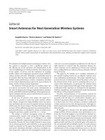
Figure 10.3 An example of state transition in E-UTRAN architecture.
E-UTRAN should have a transition time of less than 100 ms from a camped state, such as Release
6 Idle Mode, to an active state such as Release 6 CELL
DCH. It also needs to provide a transition
time of less than 50 ms between a dormant state such as Release 6 CELL
PCH and an active state
such as Release 6 CELL
DCH. An example of state transition in E-UTRAN is shown in Figure 10.3.
It is also required that the possibility for a RAN U-plane latency below 10 ms should be included.
The U-plane delay is defined as the one-way transit time between a packet being available at the IP
layer in either the UE/RAN edge node and the availability of this packet at the IP layer in the RAN
edge node/UE. The RAN edge node is the node providing the RAN interface toward the core network.
Specifications should enable an E-UTRA U-plane latency of less than 5 ms in unload conditions (i.e.
a single user with a single data stream) for small IP packet, for example, zero byte payload plus
IP headers. Obviously, E-UTRAN bandwidth allocation modes may impact the experienced latency
substantially.
The protocol stacks for the C-plane and U-plane are shown in Figures 10.8 and 10.7, respectively.
Data throughput
The DL data throughput in E-UTRAN will be three to four times higher than that specified in the
Release 6 HSDPA UL specifications in terms of an averaged user throughput per MHz. It is noted
that the DL throughput performance concerned has assumed that the Release 6 reference performance
is based on a single Tx antenna at the Node B with an enhanced performance type one receiver in
the UE; while the E-UTRA may use a maximum of two Tx antennae at the Node B and two Rx
antennae at the UE. Also, it is understandable that the supported user throughput should scale with
the spectrum bandwidth allocation schemes.
On the other hand, the UL throughput in E-UTRAN will be two to three times higher than that
given in the Release 6 Enhanced Uplink or the HSUPA in terms of averaged user throughput per
MHz. It is assumed that the Release 6 Enhanced Uplink is deployed with a single Tx antenna at the
UE and two Rx antennae at the Node B; and the E-UTRA uses a maximum of a single Tx antenna at
the UE and two Rx antennae at the Node B. Of course, a greater user throughput should be achievable
using more Tx antennae at the UE.
Spectrum efficiency
E-UTRA should deliver significantly improved spectrum efficiency and increased cell edge bit rate
while maintaining the same site locations as UTRAN and GERAN deployed today.
In a loaded network, the spectrum efficiency in the DL channels in E-UTRAN should be three to
four times higher than the Release 6 HSDPA if measured in bits/sec/Hz/site. This should be achieved
E-UTRAN: 3GPP’S EVOLUTIONAL PATH TO 4G 403
assuming that the Release 6 reference performance is based on a single Tx antenna at the Node B
with enhanced performance type 1 receiver in UE; while the E-UTRA may use a maximum of two
Tx antennae at the Node B and two Rx antennae at the UE.
The spectrum efficiency in the UL channels in E-UTRAN should be two to three times higher than
the Release 6 Enhanced Uplink deployed with a single Tx antenna at the UE and two Rx antennae at
the Node B. This spectrum efficiency in the UL channels in E-UTRAN should be achievable by the
E-UTRA using a maximum of a single Tx antenna at the UE and two Rx antennae at the Node B.
It should be noted that the discrepancy in the spectrum efficiency between the DL and UL channel
underlines the different operational environments between the DL and UL. Usually, the UL is much
more susceptive to channel impairments, such as multipath interference, and so on, and thus the cost
to maintain a satisfactory detection efficiency in UL channels is higher than that in DL channels.
E-UTRAN should support a saleable bandwidth allocation scheme, that is, 5, 10, 20, and possibly
15 MHz. Support to scale the bandwidth in an increment factor of 1.25 or 2.5 MHz should also be
considered to allow flexibility in narrow spectral allocations where the system may be deployed.
Mobility support
E-UTRAN should be optimized in terms of its performance for low mobile users at a speed from 0
to 15 km/h. Higher mobile users at a speed between 15 and 120 km/h should be supported with a
satisfactorily high performance. Supportable mobility across the cellular networks should be main-
tained at speeds from 120 km/h to 350 km/h (or even up to 500 km/h depending on the frequency
band allocated). The provision for mobility support up to 350 km/h is important to maintain an
acceptable service quality to the users who need the services at high-speed railway systems, such
as the Euro-Star trains running between the United Kingdom and France. In such a case, a special
scenario applies for issues such as mobility solutions and channel models. For the physical layer
parameterizations, E-UTRAN should be able to maintain the connection up to 350 km/h, or even up
to 500 km/h depending on the frequency band.
The E-UTRAN should also support techniques and mechanisms to optimize delay and packet loss
during intrasystem handovers. Voice and other real-time services supported in the Circuit Switched
(CS) domain in R6 should be supported by E-UTRAN via the PS domain with a minimum of equal
quality as supported by UTRAN (e.g. in terms of guaranteed bit rate) over the whole speed range.
The impact of intra E-UTRA handovers on quality (e.g. interruption time) should be less than or
equal to that provided by CS-domain handovers in GERAN.
Coverage
E-UTRA should be sufficiently flexible to support a variety of coverage scenarios for which the
aforementioned performance targets should be met assuming the reuse of existing UTRAN sites and
the same carrier frequency. For more accurate comparisons, reference scenarios should be defined
that are representatives of the current UTRAN (WCDMA) deployments.
The throughput, spectrum efficiency, and mobility support mentioned above should be met for
5 km cells in radius, and with a slight degradation for 30 km cells in radius. A cell range of up to
100 km should not be precluded.
As mentioned earlier, E-UTRAN should operate in spectrum allocations of different bandwidths,
such as 1.25 MHz, 2.5 MHz, 5 MHz, 10 MHz, 15 MHz, and 20 MHz, in both the UL and DL.
Operations in paired and unpaired spectra should also be supported. Operation in paired and unpaired
spectra should not be excluded.
The system should be able to support content delivery over an aggregation of resources, including
Radio Band Resources (as well as power, adaptive scheduling, etc.) in same as well as different bands,
in both UL and DL, and in both adjacent and nonadjacent channel arrangements. A “Radio Band
Resource” is defined as an all spectrum available to an operator.
404 E-UTRAN: 3GPP’S EVOLUTIONAL PATH TO 4G
Enhanced MBMS
Multimedia Broadcast Multicast Service (MBMS), has been introduced in 3GPP UTRAN services.
E-UTRA systems should support enhanced MBMS modes if compared to UTRA operation. For the
unicast case, E-UTRA should be capable of achieving the target performance levels when operating
from the same site locations as existing UTRA systems.
E-UTRA should provide enhanced support for MBMS services. Specifically, E-UTRA’s support
for MBMS should take the following requirements into account. (1) Physical Layer Component
Reuse: in order to reduce E-UTRA terminal complexity, the same fundamental modulation, coding,
and multiple access approaches used for unicast operations should apply to MBMS services, and the
same UE bandwidth mode set supported for unicast operations should be applicable to the MBMS
operation. (2) Voice and MBMS: the E-UTRA approach to MBMS should permit simultaneous, tightly
integrated, and efficient provisioning of dedicated voice and MBMS services to the user. (3) Unpaired
MBMS Operation: the deployment of E-UTRA carriers bearing MBMS services in unpaired spectrum
arrangements should be supported.
Spectrum deployment
E-UTRA is required to work with the following spectrum deployment scenarios:
• Coexistence in the same geographical area and colocation with GERAN/UTRAN on adjacent
channels.
• Coexistence in the same geographical area and colocation between operators on adjacent
channels.
• Coexistence on overlapping and/or adjacent spectra at country borders.
• E-UTRA should possibly operate stand-alone, that is, there is no need for any other carrier to
be available.
• All frequency bands should be allowed following release of independent frequency band
principles.
It is noted that in case of border coordination requirements, other aspects such as possible schedul-
ing solutions should be considered, along with other physical layer behaviors.
Coexistence and interworking with 3GPP RAT
E-UTRAN should support interworking with existing 3G systems and non-3GPP specified systems.
E-UTRAN should provide a possibility for simplified coexistence between the operators in adjacent
bands as well as cross-border coexistence.
Basically, all E-UTRAN terminals that are also supporting UTRAN and/or GERAN operations
should be capable of supporting the measurement of, and the handover from and to, both 3GPP
UTRA and 3GPP GERAN systems. In addition, E-UTRAN is required to efficiently support inter-
RAT (Radio Access Technology) measurements with an acceptable impact on terminal complexity
and network performance, for instance, by providing UEs with measurement opportunities through
DL and UL scheduling.
Therefore, note that the question here is not about backward compatibility, but only about the
support for handover mechanism between different 3GPP networks. Also note that HSPDA is still
a 3G solution from 3GPP, and it is fully backward compatible to WCDMA networks. Backwards
compatibility is highly desirable in E-UTRAN, but the trade-off versus performance and/or capabil-
ity enhancements should be carefully considered. It is interesting to note that, like the compatible
problems existing between UTRAN (based on WCDMA) and GERAN (based on GSM), the problem
has surfaced again here between E-UTRAN and UTRAN.
E-UTRAN: 3GPP’S EVOLUTIONAL PATH TO 4G 405
Requirements that are applicable to interworking between E-UTRA and other 3GPP systems are
listed below:
• The interruption time during a handover of real-time services between E-UTRAN and UTRAN
should be less than 300 ms.
• The interruption time during a handover of non real-time services between E-UTRAN and
UTRAN should be less than 500 ms.
• The interruption time during a handover of real-time services between E-UTRAN and GERAN
is less than 300 ms.
• The interruption time during a handover of non real-time services between E-UTRAN and
GERAN should be less than 500 ms.
• Nonactive terminals (such as the one in Release 6 idle mode or CELL
PCH) that support
UTRAN and/or GERAN in addition to E-UTRAN should not need to monitor paging messages
only from one of GERAN, UTRA or E-UTRA.
The above requirements are set for the cases where the UTRAN and/or GERAN networks provide
support for E-UTRAN handovers. The interruption times required above are to be considered as
maximum values, which may be subject to further modifications when the overall architecture and
the E-UTRA physical layer has been defined in more detail.
Architecture and migration
A single E-UTRAN architecture should be agreed upon in TSG. The E-UTRAN architecture should
be packet-based, although provisions should be made to support real-time and conversational class
traffic. E-UTRAN architecture should simplify and minimize the number of interfaces where possible.
E-UTRAN should offer a cost-effective migration from Release 6 UTRA radio interface and
architecture. The design of the E-UTRAN network should be under a single E-UTRAN archi-
tecture, which should be packet-based (thus, all IP wireless architecture will be dominant in the
E-UTRAN networks), although provisions should be made to support real-time and conversational
class traffic.
E-UTRAN architecture should minimize the presence of “single point of failures,” and thus some
backup measures should be considered. The E-UTRAN architecture should support an end-to-end
Quality of Service (QoS) requirement. Also, backhaul communication protocols should be optimized
in E-UTRAN. QoS mechanism(s) should take into account the various types of traffic that exist to
provide efficient bandwidth utilization.
E-UTRAN should efficiently support various types of services, especially from the PS domain
(e.g. Voice over IP, Presence). The E-UTRAN should be designed in such a way as to minimize the
delay variation (jitter) for the TCP/IP packet communication.
Radio resource management
As mentioned earlier, the E-UTRAN RR management requires that: (1) an enhanced support for
end-to-end QoS is in place; (2) efficient support for transmission of higher layers is needed; and
(3) the support of load sharing and policy management across different Radio Access Technologies
is necessary.
Complexity issues
E-UTRA and E-UTRAN should satisfy the required performance. Additionally, system complexity
should be minimized in order to stabilize the system and interoperability in the earlier stages; it also
406 E-UTRAN: 3GPP’S EVOLUTIONAL PATH TO 4G
serves to decrease the cost of terminal and UTRAN. To fulfill these requirements, the following points
should be taken into account.
To reduce the implementation complexity in both hardware and software, the design of E-UTRAN
networks should minimize the number of options, and also ensure the elimination of any redundant
mandatory features. It is also important to reduce the number of necessary test cases, for example,
to reduce the number of the states of protocols, minimize the number of procedures, appropriate
parameter range, and granularity.
The proposed E-UTRA/E-UTRAN requirements should minimize the complexity of the E-UTRA
UE in terms of size, weight, and battery life (standby and active), which should be consistent with
the provision of the advanced services of the E-UTRA/UTRAN. To satisfy these requirements, the
following factors should be taken into account:
• UE complexity in terms of its capability to support multi-RAT (GERAN/UTRA/E-UTRA)
should be considered when considering the complexity of E-UTRA features.
• The mandatory features should be kept to the minimum.
• There should be no redundant or duplicate specifications of mandatory features, for accom-
plishing the same task.
• The number of options should be minimized. Sets of options should be realizable in terms
of separate distinct UE types/capabilities. Different UE types/capabilities should be used to
capture different complexity versus performance trade-offs, for instance, for the impact of
multiple antennae.
• The number of necessary test cases should be minimized so it is feasible to complete the
development of the test cases within a reasonable time frame after the Core Specifications are
completed.
10.4 E-UTRAN Study Items
The E-UTRAN WGs have dedicated normal meeting times to the Evolution activity, as well as
separate Ad Hoc meetings. RAN WG1 held one of these Ad Hoc meetings on June 20–21, 2005
(3GPP TSG RAN WG1 Ad Hoc on UTRA/UTRAN LT evolution, held in Sophia Antipolis, France),
where it started looking at, and evaluating new air-interface schemes. A set of six basic layer 1 or
physical layer proposals were then agreed for further study, which included the following:
• FDD UL based on SC-FDMA, FDD DL based on OFDMA
• FDD UL based on OFDMA, FDD DL based on OFDMA
• FDD UL/DL based on MC-WCDMA
• TDD UL/DL based on MC-TD-SCDMA
• TDD UL/DL based on OFDMA
• TDD UL based on SC-FDMA, TDD DL based on OFDMA.
The evaluations of these technologies against the requirements for the physical layer are collected
in TR25.814 [818].
The TSG RAN WG2 has also organized the first meeting to propose and discuss the air-interface
protocols of the Evolved UTRAN [819]. Although the details of these are very dependent on the
solutions chosen for the physical layer, some assumptions, and agreements have been taken, which
are summarized as follows:
• Simplification of the protocol architecture and the actual protocols is necessary.
E-UTRAN: 3GPP’S EVOLUTIONAL PATH TO 4G 407
• There should be no dedicated channels, and so they form a simplified Medium Access Control
(MAC) layer (without MAC-d entity).
• A debate over Radio Resource Control (RRC) was held. It is generally supported that it should
be simplified and have less states. The location of its functions is open.
• Currently, there are very similar functions in the Radio Network and the Core. This should be
simplified.
• Other open issues include: (1) Macro diversity.
1
(2) Security and ciphering; (3) Handover sup-
port; and (4) Measurements.
The TSG RAN WG3 (as shown in Figure 10.2, the fifth layer from the top in the second column
from the left) is working closely with SA WG2 (as shown in Figure 10.2, the fourth layer from
the top in the third column from the left) in the definition of the new E-UTRAN architecture. SA
WG2 has started its own study for the System Architecture Evolution whose objective is to develop
a framework for an evolution or migration of the 3GPP system to a higher-data-rate, lower-latency,
and packet-optimized system that supports multiple RATs. The focus of this work will be on the PS
domain with the assumption that voice services are supported in this domain.
This study builds on the RAN Long-Term Evolution and on the All-IP Network work carried out
in SA WG1, and a long list of open points that needed clarification were identified, which include
the items stated below.
First, how will we achieve mobility within the Evolved Access System? This issue is closely
associated with the ways to overcome serious Doppler spread problems in a fast fading channel envi-
ronment. As the allowed mobility supported in E-UTRAN will be higher than the 3GPP 3G system,
this problem is very critical to the overall success of the E-UTRAN project.
Then, is the Evolved Access System envisioned to work on new and/or existing frequency bands?
As 3GPP UTRAN is working in 2 GHz carrier frequency bands with its bandwidth being 5 MHz, the
E-UTRAN may not be suitable for its operation in the same 2 GHz band as WCDMA is. The main
reason is that E-UTRAN can work on a much wider bandwidth (up to 20 MHz), and the existing
bandwidth allocation at 2 GHz is already very crowded. The real situation could be different from
country to country. As an example, the US radio spectrum allocation situation can be seen from
Figure 9.1 [792].
The more frequently discussed issues in SA WG1 include the following:
• Is connecting the Evolved RAN to the legacy PS core necessary?
• How do we add support for non-3GPP Access Systems (ASs)?
• WLAN 3GPP IP AS might need some new functionalities for Intersystem Mobility with the
Evolved AS.
• Clarify which interfaces are the roaming interfaces, and how roaming works in general.
• The issues on inter-AS mobility should be discussed.
• Possible difference between PCC functionalities, mainly stemming from the difference in how
Inter-AS mobility is provided.
• How do UEs discover ASs and corresponding radio cells? The options include autonomous
per AS versus the UEs scans/monitors of any supported AS to discover systems and cells.
Or, do ASs advertise other ASs to support UEs in discovering alternative ASs? How is such
advertising performed (e.g. system broadcast, requested by UE, etc.)? How do these procedures
impact battery lifetime?
1
General agreement is that it should be avoided in the DL design.
408 E-UTRAN: 3GPP’S EVOLUTIONAL PATH TO 4G
G
x
Figure 10.4 The E-UTRAN Model architecture B1 for non-roaming scenario, where R1,R2andR
are working names for reference points; G
x
+ denotes evolved or extended G
x
; PCRF1 represents
evolved Policy and Charging Rules Function; the dash links and circles represent new functional
elements/interfaces in E-UTRAN architecture.
• In the case of ASs advertising other ASs: will any AS provide seamless coverage (avoiding the
loss of network/network search), or is a hierarchy of ASs needed to provide seamless coverage
for continuous advertisement?
The two model architectures [820], which summarize the broad range of proposals that have been
presented in several WG meetings, are shown in Figures 10.4 and 10.5. Note that the key difference
in the two model E-UTRAN architectures lies in the way that intersystem mobility is achieved and
managed, and thus the interactions among the E-UTRAN network and other 3GPP networks, such as
UTRAN (based on WCDMA technology) and GERAN (based on GSM standard).
10.5 E-UTRAN TSG Work Plan
As mentioned earlier, the E-UTRAN standardization process is still going on. Only some very general
technical aspects have been agreed upon in the TSG RAN meetings, and even for them the subsequent
meetings can revise them from time to time. So far, a detailed work plan of the aforementioned Study
Items has been made by 3GPP and can be summarized in terms of the milestones per TSG RAN
E-UTRAN: 3GPP’S EVOLUTIONAL PATH TO 4G 409
Figure 10.5 The E-UTRAN Model architecture B2, where R
h
provides functionality to prepare han-
dovers so that interruption time is reduced. It is intended that this interface should be generic enough
to cope with other combinations of RATs, for which handover preparation is needed. G
x
+ denotes
G
x
with added Inter-Access-System mobility support. W
x
+ denotes W
x
with added Inter-Access-
System mobility support. Inter-AS MM denotes Inter-Access-System Mobility Management. PCRF2
elements are drawn twice only for figure topology reasons. PCRF2 represents the evolved Policy and
Charging Rules Function. The dash links and circles represent new functional elements/interfaces in
E-UTRAN architecture.
meetings. The work plan for SAE is included below by taking into account the time alignment
between the LTE and SAE works.
TSG RAN #28 meeting (June 2005, Quebec)
• Revised Work plan;
• Requirement TR Approved: (1) Deployment Scenarios included; (2) Requirements on Migra-
tion Scenarios included.
TSG RAN #29 meeting (September 2005, Tallin)
Revised Work plan
TSG RAN #30 meeting (December 2005, MT)
• Revised Work plan;
• Physical Layer basics: (1) Multiple access scheme; (2) Macro diversity or not.
410 E-UTRAN: 3GPP’S EVOLUTIONAL PATH TO 4G
TSG RAN #31 meeting (March 8–10, 2006, China)
• More detailed L1 concepts to be used for evaluation, such as: (1) MIMO scheme; (2) Intercell
interference mitigation scheme; (3) Scheduling and link adaptation principles; (4) Physical
channel structure (including control signaling, reference signals).
• Simulation conditions and methodology for the system evaluation.
• RF Scenarios.
• Radio Interface Protocol Architecture: Functions of RRC, MAC, and so on.
• RAN Architecture including migration scenarios: (1) Radio interface protocol termination
points: RRC, Outer ARQ termination points, and so on; (2) Security: User-plane and control-
plane ciphering; Control-plane integrity protection.
• Core Network Architecture related to E-UTRA/UTRA/GSM: (1) Control-plane functional ter-
mination points; (2) User-plane functional termination points.
• Overall System Architecture: Nodes and interfaces related to E-UTRA/UTRA/GSM.
• States and state transitions: (1) Final state model; (2) State transition between E-UTRA and
UTRA/GERA.
• Intra E-UTRA and E-UTRA-UTRA/GSM mobility in Active and Idle modes: (1) Mobility
concept including measurements and signaling; (2) Interruption time node and interface budget.
• Service Requirements: (1) Are there any legacy service requirements that are obsolete? Or are
they still very important? (2) Location Services.
• Legal intercept Requirements.
• Revised work plan.
TSG RAN #32 meeting (May 31–June 2, 2006, Poland)
• RAN TR25.912 ready for approval: (1) TR has its level of details at stage 2 and this is nec-
essary for the smooth transition to Work Item phase; (2) The TR should include performance
assessments, UE capabilities, and system and terminal complexities.
• Mobility between 3GPP and non-3GPP accesses.
• QoS concept.
• MBMS architecture.
• Documentation of overall system migration scenarios.
• Optimal routing and roaming including local breakout.
• Addressing/identification requirements and solutions.
• SA2 TR ready for approval: (1) Containing architecture diagram showing the main functional
entities and interfaces; (2) Signaling flow diagram with delay estimations.
• Work Items created and their time plans agreed.
More information about the upcoming TSG RAN meetings for E-UTRAN architecture is shown
in Figure 10.6.
E-UTRAN: 3GPP’S EVOLUTIONAL PATH TO 4G 411
RAN 1,2,3,4+SA2 Joint,
29 Aug–2 Sept London
RAN-CN functional split
agreed
RAN 1,2,3,4 Joint,
7–11 Nov ASIA
RAN 1,2,3,4
Joint, Feb-06
– Refinement of
concept based on
evaluation results
RAN 1,2,3,4 Joint,
May-06
– Final evaluation
results
RAN 3+SA2 joint, 27
June–1 Jul,
Montreal
RAN 1,2,3,4
joint, 7–8
March, Tokyo
SA #28,
14–17 March,
Tokyo
SA #31,
13–16 March,
China
SA #32,
5–8 June,
TBD
SA #28,
6–9 June,
Quebec
RAN 1,2,3,4+SA2
joint, 9–13 May,
Athens
RAN-CN
functional split
RAN-CN functional split
RAN-CN functional split
RAN 1,2,3,4+SA2 joint,
30–31th May,
Quebec
Mar Apr May Jun
Mar Apr May Jun
Jul Aug Sep Oct
Dec Jan Feb
RAN 1,2,3,4+SA2
joint, 19–20 Sept,
Tallin
RAN-CN functional split
tentative
SA #29,
26–29 Sept,
Tallin
SA #30,
5–8 Dec, Malta
RAN1 #40bis, 2
4–8 Apr, Beijing
RAN1, RAN2-
Ad Hoc on LTE
20–21 June,
Sophia Antipolis
SA1 #28
4–8 Apr,
Beijing
SA1 #29
11–15 Jul,
Povoa de varzim
SA2 #45
4–8 Apr,
Beijing
SA2 #46
9–13 May,
Athens
SA2 #47
27 Jun–1 Jul,
Montreal
SA2 #48
5–9 Sep,
Sophia Antipolis
RAN1 #41, 2,3,4
9–13 May,
Athens
RAN 1,2,3,4
29 Aug–2 Sep,
London
RAN 1,2,3,4
7–11 Nov, ASIA
RAN #32
31 May–2 June,
TBD
RAN #31
8–10 March,
China
RAN #27,
9–11 March,
Tokyo
RAN #28,
1–3 June,
Quebec
RAN #29,
21–23 Sept,
Tallin
RAN #30
30 Nov–2 Dec,
MT
2006
2005
Nov
SA1 #30
24–28 Oct,
Vancouver
RAN 1,2,3,4
Feb, TBD
RAN 1,2,3,4
May, TBD
Figure 10.6 The tentative schedule for the upcoming 3GPP TSG
RAN and SA LTE joint meetings schedule for the E-UTRAN architecture
standard.
Therefore, it is seen that the E-UTRAN standardization process has not
yet been finalized.
412 E-UTRAN: 3GPP’S EVOLUTIONAL PATH TO 4G
10.6 E-UTRAN Radio Interface Protocols
This section is to describe the radio-interface protocol evolution for Evolved UTRA and Evolved
UTRAN [821]. This activity involves the TSG RAN working group of the 3GPP studies for evolution
and has impacts both on the UE and the Access Network of the 3GPP systems. It should be noted
that the information provided in this section should not be considered as the final standard, but rather
only the results from the discussions made in various 3GPP TSG WG meetings held previously up
to the time when this book was written.
Before introducing the E-UTRAN Radio Interface Protocols, we would like to define various
acronyms used in the discussions followed, as shown in Table 10.1.
10.6.1 E-UTRAN Protocol Architecture
The E-UTRAN protocol architecture bears a similar form as the one defined for the UTRAN. Two
layered protocol stacks have been defined for the E-UTRAN, including the user-plane protocol stack
and the control-plane protocol stack, as shown in Figures 10.7 and 10.8, respectively.
It is to be noted that in the E-UTRAN user-plane protocol stack, a MAC sublayer exists right
above the physical layer (or Layer-1). The dashed line in Figure 10.7 means that the existence of a
separate RLC layer is still open. The Packet Data Convergence Protocol (PDCP) will exist in the
E-UTRAN protocol stack with its exact functionalities to be revisited in the future.
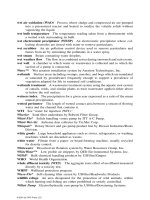
Table 10.1 Various acronyms used in the discussions on E-UTRAN Radio Interface
Protocols
ARQ Automatic Repeat Request
AS Access Stratum
CN Core Network
DL Downlink
E-UTRAN Evolved UMTS Terrestrial Radio Access Network
HARQ Hybrid Automatic Repeat Request
HO Handover
L1 Layer 1 (physical layer)
L2 Layer 2 (data link layer)
L3 Layer 3 (network layer)
MAC Medium Access Control
NAS Nonaccess Stratum
NW Network
PDCP Packet Data Convergence Protocol
PDU Protocol Data Unit
RAN Radio access network
RLC Radio Link Control
RRC Radio Resource Control
SDU Service Data Unit
TCH Traffic Channel
UE User Equipment
UL Uplink
UMTS Universal Mobile Telecommunications System
UTRA UMTS Terrestrial Radio Access
UTRAN UMTS Terrestrial Radio Access Network
E-UTRAN: 3GPP’S EVOLUTIONAL PATH TO 4G 413
Figure 10.7 The E-UTRAN user-plane protocol stack.
Figure 10.8 The E-UTRAN control-plane protocol stack.
On the other hand, the E-UTRAN control-plane protocol stack also has a MAC sublayer. Similar
to the one in the user-plane, the existence of a separate RLC entity is still undetermined. A simplified
RRC layer will be used in the E-UTRAN standard.
10.6.2 E-UTRAN Layer 1
Layer 1 in E-UTRAN is defined as exactly the same as what we often refer to in the Physical Layer.
In this subsection, we will introduce the service, functions, and transport channels of Layer 1 (or the
physical layer) in the E-UTRAN architecture.
The physical layer offers information transfer services to MAC and all other higher sublay-
ers/layers, as shown in Figures 10.7 and 10.8. The physical layer transport services are described by
how and with what characteristics data are transferred over the radio interface. An adequate term for
this is “Transport Channel.” It should be noted that, on the other hand, the classification of what is
transported is what relates to the concept of logical channels at the MAC layer.
Downlink transport channels
There are three types of DL transport channels in total, which are explained as follows:
• Broadcast Channel (BCH): characterized by (1) low fixed bit rate; (2) requirement to be broad-
cast in the entire coverage area of the cell.
414 E-UTRAN: 3GPP’S EVOLUTIONAL PATH TO 4G
• Downlink Shared Channel (DL-SCH): characterized by: (1) the possibility of using HARQ;
(2) the possibility of applying link adaptation by varying the modulation, coding, and transmit
power; (3) the possibility to be broadcast in the entire cell; (4) the possibility to use beam-
forming; (5) dynamic or semistatic resource allocation; (6) the possibility of channel-quality
indication (CQI) reporting;
2
and (7) the support of UE power saving.
3
• Paging Channel and Notification Channel (PCH and NCH): characterized by: (1) the support
of UE power saving; (2) the requirement to be broadcast in the entire coverage area of the cell.
Uplink transport channels
There are two types of UL transport channels, which are explained as follows:
• Uplink Shared channel (UL-SCH):
4
characterized by: (1) the possibility to use beam-forming;
(2) the possibility of applying link adaptation by varying the transmit power and potentially
modulation and coding; (3) the possibility to use HARQ; (4) dynamic or semistatic resource
allocation;
5
(5) the possibility of CQI reporting.
6
• Random Access Channel(s) (RACH):
7
characterized by: (1) limited data field; (2) collision
risk; and (3) the possibility of using HARQ.
10.6.3 E-UTRAN Layer 2
Layer 2 in the E-UTRAN protocol architecture consists of three sublayers, including the MAC sub-
layer, the RLC sublayer and the PDCP sublayer.
The MAC sublayer provides data transfer services on logical channels. A set of logical channel
types is defined for different kinds of data transfer services as offered by MAC. Each logical channel
type is defined by what type of information is transferred.
Some RR control (scheduling of user data, common channel transmissions, resource allocations,
etc.) is also performed in MAC. MAC should: (1) be QoS aware; (2) assign resource blocks based on
QoS attributes, buffer occupancy, and radio measurements; (3) include support of HARQ mechanism;
(4) include segmentation/reassembly, if taken out of RLC and considered needed in L2. The possibility
to cipher all flows in MAC exists.
A general classification of logical channels is divided into two groups: Control Channels (for the
transfer of control-plane information) and Traffic Channels (for the transfer of user-plane information).
MAC Control Channels
Control channels are used for the transfer of control-plane information only. There are five different
control channels offered by MAC.
• Broadcast Control Channel (BCCH): A DL channel for broadcasting system control information.
2
Some new attributes should be discussed on whether there should be two types of DL-SCH.
3
This function of DL-SCH is about an association with a physical layer signal, the Page Indicator, to support
efficient sleep mode procedures.
4
It is to be noted that the possibility of using UL synchronization and timing advance depends on the physical
layer.
5
Note: This is a new attribute for future studies on whether there should be two types of UL-SCH.
6
It is also a study topic on whether a Random Access Channel is included. If yes, it will be characterized by
the following attributes.
7
The possibility to use open-loop power control depends on the physical layer solution.
E-UTRAN: 3GPP’S EVOLUTIONAL PATH TO 4G 415
• Paging Control Channel (PCCH) and Notification Control Channel (NCCH): A DL channel
that transfers paging information (and notifications for MBMS). This channel is used when the
network does not know the location cell of the UE.
• Common Control Channel (CCCH): This channel is used by the UEs having no RRC connection
with the network.
8
• Multicast Control Channel (MCCH):
9
a point-to-multipoint DL channel used for transmitting
MBMS scheduling and control information from the network to the UE, for one, or several
MTCHs. After establishing an RRC connection, this channel is only used by UEs that receive
MBMS.
10
• Dedicated Control Channel (DCCH): A point-to-point bidirectional channel that transmits ded-
icated control information between a UE and the network. Used by UEs having an RRC
connection.
MAC Traffic Channels
Traffic channels are used for transferring user-plane information only. The traffic channels offered by
MAC include:
• Dedicated Traffic Channel (DTCH): A DTCH is a point-to-point channel, dedicated to one UE,
for the transfer of user information. A DTCH can exist in both UL and DL.
• Multicast Traffic Channel (MTCH): A point-to-multipoint DL channel for the transmission of
traffic data from the network to the UE.
Mapping between logical channels and transport channels
Another important function in the E-UTRAN MAC sublayer is to perform the mapping between the
logical channels and the transport channels.
The mapping in UL concerns the connections between logical channels and transport channels,
to be explained as follows:
• CCCH can be mapped to RACH;
11
• CCCH can be mapped to UL SCH;
12
• DCCH can be mapped to RACH;
• DCCH can be mapped to UL SCH;
• DTCH can be mapped to UL SCH.
8
This needs further study, depending on whether the access mechanism is contained in L1. If RACH is visible
as a transport channel, CCCH will be used by the UEs when accessing a new cell or after cell reselection.
9
This needs a study on whether it is distinct from CCCH.
10
Note that the old version is MCCH +MSCH.
11
This needs further study if the access procedure is not contained within L1.
12
Further study is required to see if just a transient (random) ID is assigned for the resource request, if the
actual RRC Connection Request message has still to contain a UE identifier and therefore such a message is
considered to be a CCCH message, and even if it is transported on the UL
SCH. Also, the UE is not yet in a
connected mode.
416 E-UTRAN: 3GPP’S EVOLUTIONAL PATH TO 4G
On the other hand, the mapping in DL concerns the connections between logical channels and
transport channels, as explained below.
• BCCH can be mapped to BCH;
• PCCH can be mapped to PCH;
13
• PCCH can be mapped to DL SCH;
14
• CCCH can be mapped to DL SCH;
• DCCH can be mapped to DL SCH;
• DTCH can be mapped to DL SCH;
• MTCH can be mapped to DL SCH;
15
• MTCH can be mapped to MCH;
16
• MCCH can be mapped to DL SCH;
17
• MCCH can be mapped to MCH.
18
RLC sublayer and PDCP sublayer
The exact functionalities of the other two sublayers in the E-UTRAN Layer 2, RLC sublayer and
PDCP sublayer, had not been determined at the time of writing this book.
Also, the proposals for the functions of the Layer 3 and many other detailed elements in the
E-UTRAN protocol architecture will be collected and discussed in the subsequent 3GPP TSG RAN
meetings scheduled in 2006, as shown in Figure 10.6.
10.7 E-UTRAN Physical Layer Aspects
As one of the most important part of the overall system architecture, the E-UTRAN physical layer
aspects is discussed in this section [822]. The details of E-UTRAN physical layer aspects have been
discussed in various 3GPP TSG RAN WG1 meetings and the discussions are continuing in the follow-
up TSG RAN WG1 meetings, which are scheduled in 2006, as shown in Figure 10.6. Therefore, the
information given in this section is only reflected from the proposals and discussions made before
the time of writing this book.
Altogether six E-UTRAN Physical Layer proposals (all of which have claimed to satisfy the
general technical features described in Section 10.3) have been discussed in 3GPP TR 25.814 [822],
which include:
• FDD UL based on SC-FDMA, FDD DL based on OFDMA
• FDD UL based on OFDMA, FDD DL based on OFDMA
13
Further study is needed to see if a separate PCH exists.
14
Further study is needed to see if a separate PCH does not exist.
15
Further study is needed to see if a separate MCH does not exist.
16
Further study is needed to see if a separate MCH exists.
17
Further study is needed to see if a separate MCCH exist.
18
Further study is needed to see if a separate MCCH and MCH exist.
E-UTRAN: 3GPP’S EVOLUTIONAL PATH TO 4G 417
• FDD UL/DL based on MC-WCDMA
• TDD UL/DL based on MC-TD-SCDMA
• TDD UL/DL based on OFDMA
• TDD UL based on SC-FDMA, TDD DL based on OFDMA
which were proposed by various different parties (including vendors and service providers, etc.).
Because of the limited space, we introduce only one such proposed Physical Layer design scheme
as an example, namely, the second scheme “FDD UL based on OFDMA, FDD DL based on OFDMA.”
However, it should be noted that E-UTRAN, similar to 3GPP UTRAN, will be designed based on
either FDD or TDD operation modes, depending on the operational environment.
10.7.1 Downlink Aspects of FDD OFDMA
The DL design based on FDD OFDMA technology is one of the proposed DL physical layer archi-
tectures in 3GPP TSG RAN LTE WGs meetings. In this scheme, the DL transmission scheme is
based on conventional OFDM using a cyclic prefix (CP), with a subcarrier spacing f = 15 kHz
and a CP duration T
CP
≈ 4.7/16.7 s (short / long CP).
Assuming that a 10 ms radio frame is divided into 20 equally sized subframes, this parameter set
implies a subframe duration T
subframe
= 0.5 ms. The basic transmission parameters are then specified
in more detail in Table 10.2. It may be noted that the information specified below is for the purpose
of evaluation only.
It is noted that in the FDD OFDMA DL scheme, subcarrier spacing is constant regardless of
the transmission bandwidth. To allow for operation in different spectrum allocation schemes, the
transmission bandwidth can be varied by using different numbers of OFDM subcarriers. The need for
supporting an additional longer cyclic-prefix duration, as shown in Table 10.2, may be necessary. The
longer CP should then be more suitable for the applications in multicell broadcast and very-large-cell
scenarios.
OFDM/OQAM modulation scheme
The FDD OFDMA
19
scheme should support two modulation schemes, one called the basic modulation
scheme and the other called the enhanced modulation scheme. The DL basic modulation schemes
include QPSK, 16QAM and 64QAM. It is also possible to use hierarchical modulation schemes for
the purpose of broadcasting. The enhanced modulation scheme is referred to OFDM modulation with
pulse shaping, namely, the OFDM/OQAM scheme.
Unlike conventional OFDM modulation, the OFDM/OQAM modulation does not require a guard
interval (also called CP). For this purpose, the prototype function modulating each subcarrier must be
accurately localized in the time domain, to limit the intersymbol interference for transmissions over
multipath channels. This prototype function can also be accurately localized in the frequency domain,
to limit the intercarrier interferences (due to Doppler effects, phase noise, etc.). This function must
also guarantee orthogonality between subcarriers both in the time and frequency domains.
It is mathematically clear that when using complex valued symbols, the prototype functions
guaranteeing perfect orthogonality at a critical sampling rate cannot be well localized both in time
and frequency. For instance, the unity function used in conventional OFDM has weak frequency
localization properties and we have to use a CP between the symbols to limit intersymbol interference.
19
The principles of orthogonal frequency division multiple access (OFDMA) has been discussed in Section 7.5.4.
418 E-UTRAN: 3GPP’S EVOLUTIONAL PATH TO 4G
Table 10.2 Parameters for downlink transmission FDD OFDMA scheme
Transmission
BW
1.25 MHz 2.5 MHz 5 MHz 10 MHz 15 MHz 20 MHz
Subframe
duration
0.5 ms 0.5 ms 0.5 ms 0.5 ms 0.5 ms 0.5 ms
Subcarrier
spacing
15 kHz 15 kHz 15 kHz 15 kHz 15 kHz 15 kHz
Sampling
frequency
1.92 MHz
(1/2 ×
3.84 MHz)
3.84 MHz 7.68 MHz
(2 × 3.84
MHz)
15.36 MHz
(4 × 3.84
MHz)
23.04 MHz
(6 × 3.84
MHz)
30.72 MHz
(8 × 3.84
MHz)
FFT size 128 256 512 1024 1536 2048
Number of
occupied
subcarriers
a
76 151 301 601 901 1201
Number of
OFDM symbols
per subframe
(Short / Long
CP)
7/6 7/6 7/6 7/6 7/6 7/6
CP length
b
Short (4.69/9)
×6,
(5.21/10)
×1
c
(4.69/18)
×5,
(4.95/19)
×2
(4.69/36)
×3,
(4.82/37)
×4
(4.75/73)
×6,
(4.82/74)
×1
(4.73/109)
×2,
(4.77/110)
×5
(4.75/146)
×5,
(4.79/147)
×2
Long (16.67/32) (16.67/64) (16.67/128) (16.67/256) (16.67/384) (16.67/512)
a
This includes DC subcarrier which contains no data. This is the assumption for the baseline proposal. It may
be possible for some more carriers to occupy a wider bandwidth.
b
The unit of “CP length” is (µs/samples).
c
(x
1
/y
1
) ×n
1
,(x
2
/y
2
) ×n
2
means (x
1
/y
1
) for n
1
OFDM symbols and (x
2
/y
2
) for n
2
OFDM symbols.
To allow the use of accurately localized functions in the time-frequency domain, OFDM/OQAM
scheme introduces a time offset between the real part and the imaginary part of the symbols. Orthog-
onality is then guaranteed only over real values. The corresponding multi-carrier modulation is an
OFDM/OQAM. The OFDM/OQAM transmitted signal is expressed by
s(t) =
n
M−1
m=0
a
m,n
i
m+n
e
2iπmν
0
t
g(t − nτ
0
)
g
m,n
(t)
(10.1)
where a
m,n
denotes the real valued information (which can be the real part or the imaginary part of
the offset complex QAM symbol) sent on the m-th subcarrier at the n-th symbol, M is the number
of subcarriers, ν
0
is the intercarrier spacing, which is the same as the classical OFDM system. τ
0
is
the OFDM/OQAM symbol duration, it is equal to T
u
/2(T
u
is the OFDM symbol duration), and g is
the prototype function.
It is important to note that the OFDM/OQAM symbol rate is twice the classical OFDM symbol
rate without CP (τ
0
= N/2); meanwhile, since the modulation used is a real one, the information
amount sent by an OFDM/OQAM symbol is only half the information amount sent by an OFDM
symbol. Figure 10.9 depicts the signal generation process of an OFDM/OQAM signal. The modulator
generates N real valued symbols at each τ
0
where τ
0
= T
u
/2. The real valued symbols are then
dephased, and are multiplied by i
m+n
before the inverse fast Fourier transform (IFFT) as shown in
Figure 10.9.
E-UTRAN: 3GPP’S EVOLUTIONAL PATH TO 4G 419
Figure 10.9 The OFDM/OQAM signal generation process for the FDD OFDMA downlink scheme
in E-UTRAN architecture.
The main difference between OFDM/OQAM and conventional OFDM signal generation lies in
the filtering by the prototype function g after the IFFT, instead of the CP addition.
Thanks to the IFFT, the prototype function g can be implemented in its polyphase form, which
greatly reduces the complexity of the filtering. Moreover, the density 2 induces some more simplifica-
tions in the polyphase implementation. Figure 10.10 illustrates a possible polyphase implementation
of both an OFDM/OQAM modulator and demodulator (G
i
are the polyphase components of the
prototype filter).
One possible candidate for the OFDM/OQAM filter (g) is the Isotropic Orthogonal Transform
Algorithm (IOTA) prototype obtained by orthogonalizing the Gaussian function in both time and
frequency domains according to the Gram-Schmidt algorithm. Another property of the IOTA is its
spectrum. Thanks to its good frequency localization, the resulting spectrum is steeper than that
generated from conventional OFDM.
A OFDM/OQAM transmitter (whose parameters are shown in Table 10.3) is very similar to the
conventional OFDM transmitter, whose parameters have been listed in Table 10.2, with a subcarrier
spacing f = 15 kHz. Assuming that a 10 ms radio frame is divided into 20 equally sized subframes,
this parameter set implies a subframe duration T
subframe
= 0.5 ms. As for conventional OFDM it may
be noted that the numerology specified below are for the purposes of evaluation only. All remarks
regarding the support of concatenated Transmission Time Interval (TTI) remain relevant.
Multiplexing and reference-signal structure
Both TDM and FDM are used in E-UTRAN FDD OFDMA DL design to map channel-coded, inter-
leaved, and data-modulated information onto OFDM time/frequency symbols. The OFDM symbols
can be organized into a number of resource blocks consisting of a number (M) of consecutive subcar-
riers for a number (N ) of consecutive OFDM symbols. It should be possible to match the granularity
of the resource allocation to the expected minimum payload. It also needs to take channel adaptation
in the frequency domain into account.
The frequency and time allocations to map information for a certain UE to resource blocks are
determined by the Node B scheduler and may depend on the frequency-selective CQI reported by
the UE to the Node B. The channel coding rate and the modulation scheme (possibly different for
different resource blocks) are also determined by the Node B scheduler and may also depend on the
reported CQI based on a time/frequency-domain link adaptation algorithm.
In addition to block-wise transmission, transmission on nonconsecutive (scattered) subcarriers is
also to be supported as a means of maximizing frequency diversity. Details of the multiplexing of
lower-layer control signaling is still to be decided but may be based on time, frequency, and/or code
multiplexing.
420 E-UTRAN: 3GPP’S EVOLUTIONAL PATH TO 4G
Figure 10.10 The OFDM/OQAM polyphase implementation for the FDD OFDMA downlink scheme
in E-UTRAN architecture.
The functionalities of DL reference signal(s) can be summarized as follows: (1) DL-channel-quality
measurements; (2) DL channel estimation for coherent demodulation/detection at the UE; and (3) Cell
search and initial acquisition.
Reference symbols (also known as “First reference symbols”) are located in the first or second
OFDM symbol of a subframe. Additional reference symbols (also known as “Second reference sym-
bols”) may also be located in other OFDM symbols of a subframe. The position (in the frequency
domain) of the reference symbols (the first as well as the second reference symbols) may vary from
subframe to subframe. The first reference symbols are always transmitted from one or multiple Tx
antennae. Currently, the issue on whether the “Second reference symbols” should be used is still open.
E-UTRAN: 3GPP’S EVOLUTIONAL PATH TO 4G 421
Table 10.3 OFDM/OQAM parameters for the downlink transmission scheme for E-UTRAN
Transmission
BW
1.25 MHz 2.5 MHz 5 MHz 10 MHz 15 MHz 20 MHz
Subframe
duration
0.5 ms 0.5 ms 0.5 ms 0.5 ms 0.5 ms 0.5 ms
Subcarrier
spacing
15 kHz 15 kHz 15 kHz 15 kHz 15 kHz 15 kHz
Sampling
frequency
1.92 MHz
(1/2 × 3.84
MHz)
3.84 MHz 7.68 MHz
(2 × 3.84
MHz)
15.36
MHz
(4 × 3.84
MHz)
23.04
MHz
(6 × 3.84
MHz)
30.72
MHz
(8 × 3.84
MHz)
FFT size 128 256 512 1024 1536 2048
Number of
occupied
subcarriers
a
76 151 301 601 901 1201
Number
of OQAM
symbols per
subframe
15
b
15 15 15 15 15
CPlength0 00000
a This includes the DC subcarrier which contains no data. This is the assumption for the baseline proposal. It
may be possible for some more carriers to occupy a wider bandwidth.
b In OFDM/OQAM the symbol rate is twice higher than that of conventional OFDM (if no CP was included)
and the amount of information transmitted per OFDM/OQAM symbol is only half the amount transmitted by
one conventional OFDM symbol.
Channel coding scheme
On the channel coding scheme used in the OFDMA scheme, the current assumption for the study-
item evaluations should be that channel coding for “normal” data is based on UTRA release 6 Turbo
coding, possibly extended to lower rates by extension with additional code polynomials, extended
longer code blocks, and modified by the removal of the tail. However, the use of alternative FEC
encoding schemes could also be considered, especially if significant benefits in terms of complexity
and/or performance can be shown. To achieve high processing gain, repetition coding can be used as
a complement to FEC. Channel coding for lower-layer control signaling is the issue to be decided.
Downlink MIMO
The baseline antenna configuration for MIMO in E-UTRAN FDD OFDMA DL design is the use of
two transmit antennae at the cell site and two receive antennae at the UE. The possibility for higher-
order DL MIMO (more than two Tx / Rx antennae) should also be considered. Aspects to consider
for the 3GPP LTE MIMO designs are given as follows: (1) Microcellular/Hot-spot and macrocellu-
lar environments should be considered in performance evaluation; (2) Not increasing the number of
operation modes unnecessarily should be ensured. The impact on receiver architecture should also be
considered; and (3) Realistic assumptions have to be taken into account when comparing different
MIMO concepts, such as feedback errors and delays, which need to consider multiantenna reference
signals overhead and its effect on performance, complexity, and signaling requirements, and so on.
The resulting reference signal and signaling overheads in both UL and DL have to be justified by the
shown improvements.
422 E-UTRAN: 3GPP’S EVOLUTIONAL PATH TO 4G
10.7.2 Uplink Aspects of FDD OFDMA
In this design scheme, proposed as a possible E-UTRAN UL architecture, the UL transmission scheme
is based on conventional OFDM using a CP as described in Section 10.7.1. The basic transmission
parameters such as subcarrier spacing, subframe duration and a CP duration are defined in Table 10.2
and are equally applicable to the UL. The need for longer CP durations is possible. It may be noted
that the specified data shown in Table 10.2 is for the purpose of performance evaluation only. It is
noted that the subcarrier spacing is constant, regardless of the transmission bandwidth. To allow for
operation in different spectrum allocation schemes, the transmission bandwidth may vary in terms of
different numbers of OFDM subcarriers.
Multiplexing and pilot structure
Two types of pilot symbols should be considered, including: (1) in band pilots, which are used for
coherent data demodulation, for example, channel estimation. These pilots are transmitted in the part
of the bandwidth used for data transmission; (2) out of band pilots, which are used for advanced
frequency dependent scheduling and link adaptation. These pilots span a larger bandwidth than the
one used for data transmission. Note that in-band pilots may also be used for frequency dependent
scheduling and link adaptation.
It was suggested that orthogonal in-band pilot (IBP) symbol patterns are needed in the following
cases: (1) If a UE transmits on two antennae (Antenna A and Antenna B) as in the case of MIMO
or transmit diversity; and (2) If multiple UEs share the same time and frequency resource, and each
of the UEs transmit on a single antenna, it is beneficial that UEs use orthogonal pilot patterns (this
is described as virtual MIMO, a specific case of spatial division multiple access (SDMA)). The
orthogonality of IBP symbol patterns can be achieved in the time and/or frequency domain.
Figure 10.11 shows an example of the IBP locations and overheads in the case that channel
allocation to a UE in the time domain is done in multiples of seven symbols (a full subframe). The
exact pilot locations and overhead are to be decided.
Figure 10.12 shows examples of the IBP location and overheads in the case that channel allocation
in the time domain to a UE is done in multiples of six symbols, implying that the first symbol in a
subframe may be used for other purposes (e.g. common control signaling). The exact pilot locations
and overheads are not determined yet. In fact, Figure 10.12 exemplifies different cases of pilot pattern
orthogonality.
Uplink MIMO
The baseline antenna configuration for UL single user MIMO is the use of two transmit antennae at
the UE and two receiver antennae at the base station. The possibility for single user higher-order UL
MIMO (more than two Tx / Rx antennae) should be considered. The possibility for SDMA should
Figure 10.11 An example of the IBP locations and overheads in the case that channel allocation to
a UE in the time domain is done in multiples of 7 symbols (a full subframe).
E-UTRAN: 3GPP’S EVOLUTIONAL PATH TO 4G 423
Figure 10.12 (a) Exemplifies the case of a single UE transmitting on a single antenna for which
no orthogonal pilot is used. (b) Exemplifies the case of a UE transmitting on multiple antennae for
which orthogonal pilot patterns are transmitted from multiple antennae. (c) Exemplifies the case of
multiple UEs, each of which transmits on a single antenna, and shares the same time and frequency
resource. Each UE transmits one orthogonal pilot pattern (virtual MIMO case).
also be considered. A specific example of SDMA corresponds to a (2 ×2) virtual MIMO, where
two UEs, each of which transmits on a single antenna, and shares the same time and frequency
resource allocation. These UEs apply mutually orthogonal pilot patterns in order to simplify cell site
processing. Note that from the UE perspective, the difference between (2 ×2) virtual MIMO and
single antenna transmission is only the use of a pilot pattern allowing for “pairing” with another UE.
PAPR reduction
The OFDMA-based UL transmission will lead to higher peak-to-average-power-ratio (PAPR) than
the single carrier transmission schemes, the level of increase being dependent on the number of
used subcarriers and/or presence of out of band pilots for the support of frequency based scheduling.
However, several digital processing based PAPR reduction techniques can be employed to mitigate
the higher PAPR for the OFDMA UL.
One approach to reduce the PAPR is the Tone Reservation (TR) method [823], in which both the
transmitter and the receiver agree to reserve a subset of tones for generating PAPR reduction signals.
424 E-UTRAN: 3GPP’S EVOLUTIONAL PATH TO 4G
Assuming that a total of N available tones and K tones are reserved. Let X be frequency-domain
data signal and C = [C
0
, C
1
, ,C
K−1
] be a code on subset . The goal of the TR method is to
find the optimum code value C so that
min
C
||x + c||
∞
= min
C
||x +
ˆ
QC||
∞
< ||x||
∞
(10.2)
where x is the time domain signal of X,
ˆ
Q is a N × K submatrix of Q, Q is the N × N inverse DFT
matrix, and ||y||
∞
is the ∞ norm of y.
In the TR method, a simple gradient algorithm with fast convergence is proposed. The overall
TR iterative algorithm can be defined as
x
i+1
= x
i
− µ ·
x
i
n
>A
α
i
n
p
n
(10.3)
where i is the iteration index variable, µ is the updating step size, and n is the index for which
sample x
n
is greater than the clipping threshold, which is defined as
α
i
n
= x
i
n
− A · exp(j · angle(x
i
n
)) (10.4)
and p
n
is called the peak reduction kernel vector. The kernel is a time domain signal that is as close as
possible to the ideal impulse at the location where the sample amplitude is greater than the predefined
threshold. This way the peak could be canceled as much as possible without generating secondary
peaks. p
n
is derived from original kernel p
0
through the right circle shifting (by n-1 samples). The
original kernel p
0
can be calculated using 2-norm criteria and is given by the following formula:
p
0
=
√
N
K
ˆ
Q1
K
(10.5)
where 1
K
is a vector of length K with all one elements.
In an example of the improved tone reservation with reduced complexity all tones except guard
band [y] are used to calculate an original kernel. Then, α combined with µ is quantified to form derived
reduction kernels. The phase is divided equally into s parts. The amplitude is divided into t parts
represented by some special values according to different FFT sizes and step lengths. For example, if
FFT size is 1024, the phase is divided equally into six parts represented by ±π/6, ±π/2, ±5π/6and
the amplitude can be chosen among 0.01, 0.04, 0.08, 0.12, and 0.16. Thus, only 30 peak reduction
kernels need to be stored.
In order to simplify the algorithm, we can only choose a fixed number of peaks to be canceled in
one iteration instead of all the peaks that satisfies
x
n
i
>A. The steps of the improved TR method
with reduced complexity is described as follows:
(A) Offline computation procedure:
• Calculate the original kernel vector p
0
based on 2-norm criteria, which is the IFFT of 1
K
(all
tones except the guard band);
• Quantify the original kernel to get derived kernels and store them in advance.
(B) Online computation procedure:
20
• Select the target PAPR value and corresponding threshold A;
• Initially, set x
0
= x;
20
This algorithm is based on each input OFDM symbol.