Wideband tdd wcdma for the unpaired spectrum phần 5 potx
Bạn đang xem bản rút gọn của tài liệu. Xem và tải ngay bản đầy đủ của tài liệu tại đây (311.99 KB, 29 trang )
82 TDD Radio Interface
RLC
BCFE
PNFE
DCFE
MAC
MAC
ctrl
AM SAP
Tr-SAP
RLC-
ctrl
L1
L1-ctrl
UM SAP
RFE
RFE
NAS
DC-SAP
GC-SAP
RRC
Nt-SAP
RFE
NAS
GC-SAP GC-SAP
Nt-SAP
Nt-SAP
DC-SAP
DC-SAP
TME
Access Stratum
RRC SAPs
SCFE
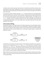
Figure 4.33 RRC Model: UE View
4.7.1.2 RRC Services and Functions
The RRC offers General Control (of the Broadcast type), Dedicated Control (of a sin-
gle UE) and Notification services (of the Paging type) to the upper layers. This is done
by the RRC layer providing a signaling connection to the upper layers. This RRC sig-
naling connection supports all the signaling requirements between the UE and a Core
Network domain.
Additionally, the Radio Resource Control (RRC) layer also controls the various protocol
entities of the Access Stratum (via Inter-Layer procedures).
The RRC services are realized via the following RRC functions:
• Management of RRC connections between the UE and UTRAN: The establishment
of an RRC connection is initiated by a request from higher layers on the UE side
to establish the first Signaling Connection for the UE. The establishment of an RRC
connection includes an admission control function (at the UTRAN) as well. The release
of an RRC connection can be initiated by a request from higher layers to release the
last Signaling Connection for the UE or by the RRC layer itself in case of RRC
connection failure. In case of connection failure, the UE requests re-establishment of
the RRC connection.
Layer 3 Communication 83
• The RRC layer also handles the assignment and reconfiguration of radio resources
(e.g. codes) needed for the RRC connection, taking into account both control and user
plane needs.
• The RRC layer performs evaluation, decision and execution related to RRC connec-
tion mobility during an established RRC connection, such as handover, preparation
of handover to GSM or other systems, cell re-selection and cell/paging area update
procedures, based on, for example, measurements done by the UE.
• Management of Radio Bearers: The RRC layer can, on request from higher layers,
perform the establishment, reconfiguration and release of Radio Bearers in the user
plane. A number of Radio Bearers can be established to a UE at the same time.
On establishment and reconfiguration, the RRC layer performs admission control and
selects parameters describing the Radio Bearer processing in Layer 2 and Layer 1,
based on information from higher layers.
• Management of QoS: This function ensures that the QoS requested for the Radio Bearers
can be met. This includes the allocation of a sufficient number of radio resources and
the appropriate assignment of processing parameters such as coding type, rate and
RM parameters.
• Resource Allocation: On the network side, RRC controls the allocation of preferred radio
resources based on long-term decision criteria as well as on a fast basis. These Radio
Resource Management (RRM) functions are discussed in great detail in Chapter 7.
• Cell Selection Reselection: On the UE side, RRC controls the selection of the most
suitable cell based on measurements and cell selection reselection criteria.
• Paging/Notification: On the network side, the RRC layer broadcasts paging and notifi-
cation information from the network to selected UEs, upon being requested by higher
layers.
• Broadcast of information: On the network side, the RRC layer performs system infor-
mation broadcasting from the network to all UEs. The system information is normally
repeated on a regular basis. The RRC layer performs the scheduling, segmentation and
repetition. The broadcast information may be related to the Access Stratum (i.e. specific
to a cell) or the Non-Access Stratum (related to the Core Network applying to more
than one cell).
Other miscellaneous functions performed are:
• UE Measurements: The measurements performed by the UE are controlled by the RRC
layer at the Network, in terms of what to measure, when to measure and how to report.
The RRC layer at the UE also performs the reporting of the measurements from the
UE to the network.
• Power Control: The RRC layer controls setting of the target of the closed loop power
control. (The Power Control topic is discussed in Chapter 5.)
• Ciphering: The RRC layer provides procedures for setting of ciphering (on/off) between
the UE and UTRAN.
• Message Integrity: This function adds a Message Authentication Code (MAC-I) to those
RRC messages that are considered sensitive and/or contain sensitive information.
• Timing Advance: The RRC controls the operation of timing advance. (Details on Timing
Advance are given in Chapter 5.)
84 TDD Radio Interface
• Routing of higher layer PDUs. At the UE, this function performs routing of higher
layer PDUs to the correct higher layer entity, and at the UTRAN, to the correct
RANAP entity.
4.7.1.3 RRC Peer-to-Peer Communication
The RRC information is exchanged between Peer RRC entities (at the UE and UTRAN)
via RRC Messages, which play the role of RRC PDUs. Some important examples are
given now. The complete list of messages is found in [6, section 10.2].
RRC CONNECTION REQUEST/SETUP
RRC STATUS
RADIO BEARER SETUP/RECONFIGURATION/RELEASE
UE CAPABILITY INFORMATION
INITIAL DIRECT TRANSFER
DOWNLINK/UPLINK DIRECT TRANSFER
PHYSICAL CHANNEL RECONFIGURATION
UPLINK PHYSICAL CHANNEL CONTROL
PHYSICAL SHARED CHANNEL ALLOCATION
TRANSPORT CHANNEL RECONFIGURATION
TRANSPORT FORMAT COMBINATION CONTROL
MEASUREMENT CONTROL/REPORT
CELL UPDATE/CONFIRM
URA UPDATE
PAGING TYPE 1 or 2
HANDOVER FROM UTRAN
SECURITY MODE COMMAND
SYSTEM INFORMATION
Each of these messages is either from the UE to the UTRAN or vice versa, and is trans-
ferred via lower layers via RLC-SAP (either using AM or UM or TM) and an appropriate
Logical Channel. For example, the RRC CONNECTION REQUEST is a message from
UE to UTRAN and uses RLC Transparent Mode over the CCCH/L logical channel.
4.7.1.4 RRC Layer-to-Layer Communication
RRC communicates with the higher sub-layers of Layer 3, namely MM and CM sublayers
as shown in Figure 4.34.
RR
ESTABLISHMENT primitives are used by the MM entity to request the RRC entity
for a Mobile Originated RR Connection and by the RRC entity to the MM-entity to indi-
cate the establishment of an RR connection. Similarly, RR
DATA primitives are used to
request transferring data between peer MM entities. Finally, RR
SYNCHRONIZATION
primitives are used to synchronize the MM entity and the RRC entity with regard to
ciphering, integrity protection, etc.
Appendix 4.1 System Information Blocks 85
CC SS SMS CC SS SMS
MMCC-
SAP
MMSS-
SAP
MMSMS-
SAP
Mobility management
sub-layer
Mobility management
sub-layer
MM-primitives
MM peer-to-peer
protocol
MS-side Network side
Radio Resource Control sublayer Radio Resource Control sublayer
RR SAP RR SAP
RRC Peer-to-Peer protocol
Access Stratum
Non-Access Stratum
Figure 4.34 RRC Inter-Layer Primitives
APPENDIX 4.1 SYSTEM INFORMATION BLOCKS
The information on BCCH/L is transmitted in the form of ‘Information Blocks’. There are
three kinds of Information Blocks: Master Information Block (MIB), Scheduling Block
(SB) and System Information Block (SIB).
Table 4.6 describes the nature of the system information carried by various blocks and
when the UE reads them. (The missing SIBs are meant exclusively for FDD and are
therefore not included here.) Note that the last column refers to RRC States, described in
Section 4.7.
Table 4.6 System Information Blocks
System
Information
Block
Area Scope Nature of System
Information
UE Mode/State
when Block
is Read
MIB Cell PLMN ID and SIB reference list Idle mode, CELL FACH,
CELL
PCH, URA PCH
SB1 Cell SIB Reference list Idle mode, CELL
FACH,
CELL
PCH, URA PCH
SB2 Cell SIB Reference List Idle mode, CELL
FACH,
CELL
PCH, URA PCH
SIB-1 PLMN NAS Info and UE Timers and
Counters
Idle
SIB-2 Cell Periodic Cell and URA Update Info URA
PCH
SIB-3 Cell Cell Selection and Re-selection
Parameters
Idle mode, CELL
FACH,
CELL
PCH, URA PCH
SIB-4 Cell Cell Selection and Re-selection
Parameters in Connected Mode.
CELL
FACH, CELL PCH,
URA
PCH
(continued overleaf )
86 TDD Radio Interface
Table 4.6 (continued )
System
Information
Block
Area Scope Nature of System
Information
UE Mode/State
when Block
is Read
SIB-5 Cell Common and Shared Physical and
Transport Channel Configuration
Parameters and Open Loop
Power Control parameters if SIB
6 is not present or does not
include OLPC parameters
Idle mode, CELL
FACH,
CELL
PCH, URA PCH,
CELL
DCH
SIB-6 Cell Common and shared Physical and
Transport Channels Configuration
Parameters in Connected Mode.
CELL
FACH, CELL PCH,
URA
PCH, CELL DCH
SIB-7 Cell Fast Changing Parameters, Dynamic
Persistence
Idle mode, CELL
FACH,
CELL
PCH, URA PCH,
CELL
DCH
SIB-11 Cell Measurement Control Information Idle mode, CELL
FACH,
CELL
PCH, URA PCH
SIB-12 Cell Measurement Control Information
in Connected Mode
CELL
FACH, CELL PCH,
URA
PCH
SIB-13 Cell ANSI-41 System Information Idle Mode, CELL
FACH,
CELL
PCH, URA PCH
SIB-14 Cell Parameters for Common and
Dedicated Physical Channel UL
Open Loop Power Control
Information
Idle Mode, CELL
FACH,
CELL
PCH, URA PCH,
CELL
DCH
SIB-15 Cell LCS (Location Service) Related
Information
Idle Mode, CELL
FACH,
CELL
PCH, URA PCH
SIB-16 PLMN Radio Bearer Transport and
Physical Channel Parameters
used during Handover to UTRAN
Idle Mode, CELL
FACH,
CELL
PCH, URA PCH
SIB-17 Cell Fast Changing Parameters for
Shared Physical and Transport
Channel in Connected Mode
CELL
FACH, CELL PCH,
URA
PCH, CELL DCH
SIB-18 Cell PLMN Ids of Neighbor Cells Idle mode, CELL
FACH,
CELL
PCH, URA PCH
REFERENCES
[1] 3GPP TS 25.301 v4.4.0, ‘3GPP; TSG RAN; BS Radio Transmission and Reception (TDD) (Release 4)’,
2002–03.
[2] 3GPP TS 25.222 v4.6.0, ‘3GPP; TSG RAN; Multiplexing and Channel Coding (TDD) (Release 4)’,
2002–12.
[3] 3GPP TS 25.223 v4.5.0, ‘3GPP; TSG RAN; Spreading and Modulation (TDD) (Release 4)’, 2002–12.
[4] 3GPP TS 25.102 v4.4.0, ‘3GPP; TSG RAN; UE Radio Transmission and Reception (TDD) (Release 4)’,
2002–03.
[5] 3GPP TS 25.105 v4.4.0, ‘3GPP; TSG RAN; BS Radio Transmission and Reception (TDD) (Release 4)’,
2002–03.
References 87
[6] 3GPP TS 25.331 v4.5.0, ‘3GPP; TSG RAN; Radio Resource Control (RRC); Protocol Specification
(Release 4)’, 2002–06.
[7] 3GPP TS 25.221 v3.4.0, ‘3GPP; TSG RAN; Physical Channels and Mapping of Transport Channels to
Physical Channels’ (Release 1999)’, 2002 –09.
[8] 3GPP TS 25.302 v4.1.0, ‘3GPP; TSG RAN; Services Provided by the Physical Layer (Release 4)’,
2001–06.
[9] 3GPP TS 25.323 v4.5.0, ‘3GPP; TSG RAN; Packet Data Convergence Protocol (PDCP) Specification
(Release 4)’, 2002–06.
[10] IETF RFC 2507 ‘IP Header Compression’.
[11] IETF RFC 3095 ‘Robust Header Compression (ROHC)’.
[12] 3GPP TS 25.324 v4.1.0, ‘3GPP; TSG RAN; Broadcast/Multicast Control (BMC) (Release 4)’, 2002–06.
5
TDD Procedures
In this chapter, a number of key procedures across the TDD Radio Interface will be
described. The procedures will be limited to those involving the UE and the UTRAN and
will not, in general, cover the Core Network. However, we will briefly address in the
last section the end-to-end procedures for user applications, which is included to illustrate
how the TDD procedures fit into the overall end-to-end applications.
The TDD procedures are highly dependent upon the so-called RRC mode of the UE.
Accordingly, we first describe the RRC Modes and associated States. Then we describe the
TDD procedures involved in the initial System Access, the User Data Transmission, the
Mobility Management and the Network (Radio-related) Operations. Finally, end-to-end
procedures are briefly described from an Application point of view.
5.1 INTRODUCTORY CONCEPTS
5.1.1 RRC Modes and States
The modes and states of the UE represent the level of activity of the RRC Layer. The two
modes of operation of the UE RRC are the Idle and Connected Modes. When the UE
powers on, it looks for a suitable cell and tunes to its control channel. The UE, by default,
enters Idle Mode. In this mode, there is no connection between the UE and the UTRAN
and the location of the UE is known only to the Core Network. The location may be known
in terms of geographic area referred to as Location Area (LA) or Routing Area (RA).
In order to move from Idle Mode to Connected Mode, the UE must establish an RRC
connection, which is initiated by the RRC Connection Establishment procedure. Upon
successful completion of the RRC Establishment procedure, the UE enters the Connected
Mode. The establishment of the RRC connection may also be initiated by the Core
Network via LA Update or RA Update procedures.
Once in Connected Mode, the UE can be in one of four states, maintained by the
UTRAN (specifically, the entity called S-RNC DCFE – Dedicated Control Function
Entity). The four states are: CELL
DCH, CELL FACH, CELL PCH and URA PCH.
From Idle Mode, the UE may enter Connected Mode into CELL
FACH or
CELL
DCH states (see Figure 5.1). The UE enters CELL DCH if a dedicated physi-
cal channel is assigned during the RRC connection establishment. Otherwise, the UE
enters the CELL
FACH state.
Wideband TDD: WCDMA for the Unpaired Spectrum P.R. Chitrapu
2004 John Wiley & Sons, Ltd ISBN: 0-470-86104-5
90 TDD Procedures
Once in CELL FACH state, a DCCH is established and the UE monitors the selected
SCCPCH/P and sends information in the PRACH/P:RACH/T. In CELL
FACH state, the
UE may perform the cell re-selection procedure and camp onto a different cell.
From CELL
FACH state, the UE transitions to CELL DCH state when a dedicated
physical channel is established. In CELL
DCH state, the UE sends DCCH/L and DTCH/L
data in the associated DCH/T transport channel. In this state, the UE mobility is managed
through handover procedures, which are commanded by the UTRAN. In the CELL
DCH
state, the UE could also use common transport channels, namely RACH/T:FACH/T.
In CELL
PCH and URA PCH states, there are no dedicated/shared data connections
between the UE and the UTRAN and the UTRAN must page to reach the UE. If the
UTRAN knows the cell in which the UE is located, then the UE is said to be in the
CELL
PCH state. On the other hand, the UTRAN may only know that the UE is located
in a group of cells, referred to as UTRAN Registration Area (URA). In this case, the
UE is said to be in a URA
PCH state and the UTRAN must page in all the cells of the
URA to reach the UE. While the UE is in these states, the UE may also initiate Cell-
Update or URA-Update procedures to reach the UTRAN. In these procedures, the UE
sends ‘Cell/URA Update’ messages on the RACH/T and returns to CELL
FACH state.
Since the physical area of URA is greater than that of a cell, the mobile UE saves more
power in the URA
PCH state than in CELL PCH as it sends Update messages less often.
However, if the UTRAN has to reach the UE in URA
PCH state, the UTRAN has to
send the page in the paging channels of all cells in the URA.
Although Idle Mode may seem similar to the CELL
PCH/URA PCH states, there are
some important differences. There is no RRC connection in Idle Mode. Furthermore, the
battery consumption could be smaller in the Idle Mode, because a smaller number of Loca-
tion Updates is typical (due to the larger area of a LA/RA compared to that of a URA/Cell).
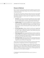
The UE modes and states transition are shown in Figure 5.1.
As shown in Figure 5.1, the UE can transition between the Idle Mode and the Connected
Mode (only CELL
FACH and CELL DCH states) via RRC Connection Establishment
and RRC Connection Release procedures.
Similarly, the UE can transition between the CELL
FACH and CELL DCH states of
the Connected Mode by establishing or releasing a Dedicated Physical Channel (DPCH).
From CELL
FACH and CELL DCH states, the UE can transition to paging states,
namely CELL
PCH and URA PCH, by appropriate signaling from the network. Con-
versely, the UE can go from the paging states to the CELL
FACH/CELL DCH states by
Cell/URA Update procedures initiated by the UE.
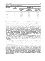
The optimal UE RRC state is in general influenced by both the UE traffic activity and
UE mobility as shown in Figure 5.2.
5.1.2 DRX/Sleep Mode
When the UE is in Idle Mode or Cell/URA
PCH states of the Connected Mode, the UE
has to perform only a small set of functions, such as maintain synchronization with the
UTRAN, perform radio measurements, receive any UTRAN initiated pages, etc. Further-
more, it is typical for a UE to be in these states/modes for an extended period of time.
As such, it is economical for the UE to enter a ‘sleep mode’ in which the power to most
of the parts of the UE is turned off, thereby extending the battery life. This sleep mode
is facilitated by the so-called Discontinuous Reception (DRX) concept.
Introductory Concepts 91
IDLE
CELL_DCH
CELL_PCH
CELL_FACH
URA_PCH
signaling
URA update procedure
or
Cell update procedure
Cell update procedure
signaling
RRC connection established
RRC connection released
DPCH established
DPCH released
signaling
RRC connection released
signaling
RRC connection established
IDLE MODE
CONNECTED MODE
Figure 5.1 UE Mode and State Transitions
Essentially, DRX is a mechanism by which a UE ‘wakes up’ at regular intervals of time
(known as DRX cycle) to perform ‘house-keeping activities’ (e.g. radio synchronization,
listening to network initiated pages, etc.) and goes to ‘sleep’ (i.e. turn off most of the
power-consuming parts of the UE) for the remainder of the DRX cycle. Alternately, the
UE may also be ‘woken up’ from the sleep mode by User-initiated activity.
Information related to DRX cycle is transmitted on the BCCH/L via SIB1/5/6 or on
DCCH/L via dedicated signaling [5]. This information consists of CN-specific DRX cycle
length coefficient (kCN), UTRAN specific DRX cycle length coefficient (kUTRAN) and
PICH/P Repetition Period (equal in value to PBP = Paging Block Period). The DRX
cycle length is given by:
UE in Idle mode:
DRX cycle length = max (2
kCN
,PBP)
UE in Connected Mode Cell/URA
PCH states:
DRX cycle length = min [max (2
kUTRAN
,PBP),max(2
kCN
,PBP)]
Clearly, a single DRX cycle may contain one or more PBPs.
92 TDD Procedures
CELL_DCH
CELL_PCH
CELL_FACH
URA_PCH
lower DTCH
activity
higher DTCH
activity
lower mobility
higher mobility
no DTCH/DCCH activity
for long time
some DTCH/DCCH
activity
Figure 5.2 Optimization of Transitions Triggered by the UTRAN According to UE Activity and
UE Mobility
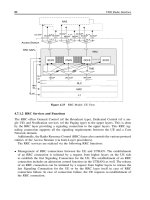
DRX Cycle Length
Frame
Offset
Figure 5.3 DRX Cycle
Since the values of kCN = 6 9, kUTRAN = 3 9, and PBP = 8, 16, 32, 64, the
possible values of the DRX cycle length are as follows:
UE in Idle mode: DRX cycle length = 0.64, 1.28, 2.56 and 5.12 seconds.
UE in CELL/URA
PCH: DRX cycle length = 0.08, 0.16, 0.32, 0.64, 1.28, 2.56 and
5.12 seconds.
The start of the DRX cycle is specified in terms of the 12-bit SFN, with an initial Frame
Offset, see Figure 5.3.
Overview of Procedures 93
5.2 OVERVIEW OF PROCEDURES
Consider a UMTS-TDD network, consisting of a number of Base Stations (Node Bs). Each
of the Base Stations broadcasts system information about the various radio parameters
that will be needed by a UE to set up communications with the BS [System Broadcast
Procedure]. The Base Stations themselves may be time synchronized with each other by
using timing references derived from GPS or by explicit signaling over the air among the
Base Stations [BS Synchronization Procedure].
In such a network, a subscriber turns on his/her user equipment, which first searches
for a suitable cell (Base Station) of an appropriate PLMN to camp on [PLMN and Cell
Search Procedure]. This is achieved by searching for the synchronization and broadcast
signals. Having camped onto a cell, the user registers himself/herself with the Network,
during which process the Network authenticates the user [Registration and Authentication
Procedures]. Now the user is ready to access the network for communication services and
vice versa. The access requests of various users are naturally uncoordinated and random
in nature [Random Access Procedure]. The service request from the Network is performed
by paging the user over areas of his/her location [Paging Procedure].
In any case, after accessing the network, a Radio Link may be established and man-
aged. This is done by first establishing a RRC connection [RRC connection Procedure]
that ensures a signaling connection to the Network, following which a Radio Bearer is
established [RB Establishment Procedure], which is subsequently modified or released
[RB Management Procedure]. In some abnormal cases, the radio link may fail, which
has to be detected and appropriate action be taken [Radio Link Failure Procedure]. On a
finer time scale, the Radio Link management consists of maintaining appropriate signal
quality via power control [Power Control Procedure] and timing misalignment control
[Timing Advance Procedure]. Finally, the user equipment may undergo periods of inac-
tivity, where the transmission may be stopped temporarily to save the battery and power
consumption and reduce system interferen ce. However, such discontinuous transmission
must make sure the synchronization is preserved [DTX procedure].
In wireless communication systems, security of communication is of great importance.
For this purpose, data on the radio interface is encrypted [Encryption Procedure] and the
integrity of signaling messages is protected by cryptographic methods [Integrity Protec-
tion Procedure].
One of the key aspects of mobile communications is Mobility Management (MM). In
this book, we shall only consider MM implemented by the Radio Access Network and
limit ourselves to Access Stratum-related procedures. In this limited context, the two rel-
evant aspects of MM are Cell Reselection and Handovers. Cell Reselection refers to the
user moving across one or more cells during periods of no activity (Idle Mode) or little
activity (CELL
FACH/CELL PCH/URA PCH states of the Connected Mode). In such
cases, the location information is updated by LA/RA Update Procedures in the Idle Mode
and Cell/URA Update Procedures in the Connected Mode. Handover relates to the case
where the user moves across a cell boundary during periods of activity (CELL
DCH of
Connected Mode). In such cases the radio link with the new cell must be established and
the one with the existing cell must be released [Handover Procedure]. Usually handovers
are limited to the UTRAN, so that the connection to the Core Network (and hence the Serv-
ing RNS) remains fixed. However, in certain cases of handover, it may be advantageous
to switch the RNS and hence the CN connection [SRNS Relocation Procedure].
94 TDD Procedures
Finally, the user conducts a communication process, such as a voice call [Circuit Call
Procedure] or an Internet Browsing Session [Packet Session Procedure].
These procedures described above are listed below:
1. System Procedures
(a) System Information Broadcast Procedures
(b) BS Synchronization Procedure
2. System and UE Access Procedures
(a) PLMN and Cell Search Procedure
(b) Registration/Authentication Procedures
(c) Random Access Procedure
(d) Paging Procedure
3. Radio Link Establishment and Management Procedures
(a) RRC Connection Procedures
(b) RAB/RB Establishment Procedures
(c) RAB/RB Management Procedures
(d) Radio Link Failure Detection and Reporting
(e) Power Control Procedures
(f) Timing Advance Procedures
(g) Radio Measurements Procedures
(h) DTX Procedures
4. Mobility Management Procedures
(a) LA/RA Update Procedures (not addressed)
(b) Cell/URA Update Procedures
(c) Handover Procedures
(d) SRNS Relocation Procedures
5. Data Transmission Procedures (across the radio interface)
6. End-to-End Communication Set-Up Procedures
(a) Circuit-Switched Call Set-Up Procedure
(b) Packet-Switched Session Set-Up Procedure.
Most of these procedures involve the UE and the Network, characterized by a sequence
of bi-directional messages that are exchanged. Exceptions include Procedure 1(a) (Sys-
tem Broadcast Procedure), which involves only messages emanating from the Network
and Procedure 1(b) (Network Synchronization Procedure), which involves only messages
within the Network (between Base Stations). Similarly, Procedure 2(a) (Cell Search
Procedure) only involves UE, and is accompanied by any messages across the Radio
Interface.
Additionally, most of the procedures listed above involve only the UTRAN and not the
Core Network. Exceptions include Procedure 2(b) (Registration/Authentication Procedure)
and Procedures 6(a) and 6(b) (End-to-End Communication Procedures). Since the focus
of the book is only on the UTRAN, these procedures will be only described briefly or
not at all.
Finally, most of the procedures involve all layers in the UTRAN, namely the Physical
Layer, the Link Layer and the Network Layer of the UTRAN (Access Stratum).
In the following sections, some of the more involved procedures are described.
PLMN/Cell Selection/Reselection Procedure 95
5.3 PLMN/CELL SELECTION/RESELECTION PROCEDURE
When a UE is switched on, typically the NAS selects a public land mobile network
(PLMN) and sends a ‘RRC PLMN Search REQ’ primitive to the AS along with PLMN
type and PLMN Identity. The UE/AS scans all RF channels in the UTRA bands and
searches for the strongest cell. If the UE/AS can read the system information, match
the PLMN identity and verify that the signal quality (RSCP of PCCPCH/P) exceeds a
threshold, then UE/AS selects the cell and informs the UE/NAS with ‘RRC PLMN Search
CNF’ primitive [2]. Figure 5.4 illustrates the procedure.
If a suitable cell is not found in the selected PLMN, the UE will attempt to camp
on ‘any’ cell. In such a case, Cell Reselection may be triggered by a NAS primitive or
autonomously by the AS at regular intervals of time. UE/AS searches for all available
PLMNs and informs the UE/NAS. If a PLMN with higher priority is found, UE/NAS
asks UE/AS to select a suitable cell (i.e. signal quality exceeds a threshold) belonging to
the PLMN with highest priority. When a suitable cell belonging to the requested PLMN
is found, that cell is selected and NAS is notified.
The UE/AS procedure for the cell search is now described [1]. During the cell search,
the UE searches for a cell and determines the downlink scrambling code, basic midamble
code and frame synchronization of that cell. The cell search is typically carried out in
three steps:
1. Primary Synchronization Code (PSC) acquisition: During the first step of the cell
search procedure, the UE uses the SCH’s primary synchronization code to find a cell.
This is typically done with a single matched filter (or any similar device) matched to
the primary synchronization code, which is common to all cells. A cell can be found
by detecting peaks in the matched filter output.
Note that for a cell of SCH slot configuration case 1, the SCH can be received
periodically every 15 slots. In case of a cell of SCH slot configuration case 2, the SCH
can be received periodically twice every 15 slots, with the second SCH slot being at
offsets of either 7 or 8 slots from the previous SCH slot. So, a SCH peak detected
every 15 time/slots indicates case 1, whereas SCH peaks separated by 7 and 8 timeslots
indicates case 2.
2. Code Group identification and slot synchronization: During the second step of the cell
search procedure, the UE uses the SCH’s Secondary Synchronization Codes (SSC)
to identify 1 out of 32 code groups for the cell found in the first step. (Recall that
there are 128 unique Cell Parameters, partitioned into 32 Code Groups with 4 C ell
Parameters each. Each Cell Parameter is uniquely identified with a pair of short and
long basic midamble codes. See Sections 3.2.2 and 4.2.1.3.)
This is typically done by correlating the received signal with the secondary syn-
chronization codes at the detected peak positions of the first step (once or twice per
frame depending upon case 1 or case 2). The primary synchronization code provides
the phase reference for coherent detection of the secondary synchronization codes. The
code group can then uniquely be identified by detection of the maximum correlation
values. (See section 4.2.1.3.)
Since the code group uniquely identifies the t
offset
parameter, the UE can derive
the slot timing from the detected peak position in the first step and the t
offset
param-
eter of the found code group in the second step. By detecting the modulation of the
96 TDD Procedures
PLMN
SEARCH
REQ
cell found?
yes
UE
NAS
UE RRC UE layer 1
SCH
CPHY_CELL SEARCH REQ
yes
L1 Receive
Initial Cell
Search
P-CCPCH
correct
PLMN?
Read SIB 3
Calculate
Srxlev
Check barring
no
yes
BCH data
value of "k"
Construct list of
UARFCNs to be
searched
CPHY_CELL_SYNC_IND
((Success: cell parameter ID, UARFCN, and
midamble correlation)
or
(Failure: all frequencies have been searched))
Configure L1 for
P-CCPCH
Read MIB for
PLMN ID
BCH data
BCH data
Srxlev>0?
cell barred?
Read SIB 5
Request L1
sync
Suitable cell
found on
selected PLMN
L1
synchronization
Figure 5.4 PLMN/Cell Selection Procedure
Random Access Procedure 97
Step-1
(PSC-
Processing)
SCH location(s)
Case-1/Case-2
Step-2
(SSC
Processing)
Step-3
(Midamble
Processing)
Cell Parameter
Basic Midamble Codes (Long and Short)
Scrambling Code
Code Group
t-offset
even/odd SFN
Figure 5.5 Cell Search Procedure
secondary synchronization codes, the UE can determine whether the SFN is even or
odd. Similarly, for case 2, the SSC modulation also reveals the SCH slot position
within one frame, e.g. first or last SCH slot.
3. Downlink scrambling code, basic midamble code identification and frame synchro-
nization: During the third and last step of the cell search procedure, the UE determines
the exact downlink scrambling code, basic midamble code and frame timing used by the
found cell. This is done by correlating each of the four possible long basic midamble
codes of the code group identified in step 2 and the midamble of the PCCPCH/P
(which is located in the same timeslot as the SCH/P). Note that a PCCPCH/P always
uses the midamble m
(1)
(and in case of SCTD also midamble m
(2)
) derived from the
long basic midamble code.
When the long basic midamble code has been identified, the downlink scram-
bling code and the cell parameter are also known. The UE can read the system-
and cell-specific BCH/T information, because the PCCPCH/P always uses a fixed and
preassigned channelization code.
Note that a cell cycles through a set of two different cell parameters according to the
SFN of a frame, e.g. the downlink scrambling code and the basic midamble code of a
cell alternate for frames with even and odd SFN. However, since the even/odd nature
of SFN is determined in step 2, this can be taken into account in decoding the BCH/T
information. These steps are depicted in Figure 5.5.
5.4 RANDOM ACCESS PROCEDURE
Random Access procedure is the means by which a UE in the Idle Mode or CELL FACH/
CELL
PCH/URA PCH states of the Connected Mode can request access for Network
Services. The procedure essentially consists of the following steps:
1. UE reads the RACH-related System Information.
2. A PRACH/P channel is selected, and the MAC and PHY (RACH/T and FACH/T)
layers are configured.
3. Access Service Class (ASC) is determined.
(a) ASC sets the relative priority for the RACH transmission. Smaller values indicate
higher priority.
(b) ASC is determined by the RRC during initial (i.e. UE in Idle-Mode) access, based
on Access Class of the UE. During subsequent accesses (i.e. UE is in Cell
FACH
98 TDD Procedures
state and RRC connection is established), ASC is determined by the MAC based
on the MLP (MAC Logical Priority) of the logical channel (CCCH/DCCH/DTCH)
in use.
4. MAC runs the backoff algorithm using the ASC value to determine whether or not to
transmit the RACH message.
(a) The backoff procedure basically generates a random number (R) and compares it to
a number (X) computed based on ASC and other parameters. X is a non-increasing
function of ASC value.
(b) The procedure is considered successful if R < X, so that lower ASC values succeed
with higher probability.
(c) When the backoff procedure succeeds, MAC selects the PRACH sub-channel and
CFN for RACH message transmission by the physical layer.
5. PHY randomly selects the channelization code and associated midamble, determines
the power level for the RACH transmission and transmits the PRACH burst.
6. In case of successful receipt, UTRAN sends an ‘ACK message’. For access via CCCH
(e.g. for RRC Connection Request or Cell Update), the ACK message is a Layer 3
message. For access via DCCH/DTCH, the ACK message is provided by Layer 2
RLC-AM entity.
It is a Layer 3 message sent via RLC Unacknowledged Mode on the FACH/T channel.
7. If UE does not receive an ACK and a Timer runs out, the RACH message is transmitted
again as per the above steps.
Figure 5.6 illustrates the main steps. For simplicity, the RLC layer between the RRC and
the MAC is not shown explicitly. During the initial access, RLC is used in its Transparent
Mode, whereas the ACK is done in the Unacknowledged Mode RLC.
System parameters related to the random access procedure are broadcast on the BCCH/L
as System Information Blocks (SIBs). (See Chapter 4 also.) Specifically, SIB-5 and SIB-6
contain the RACH/T and PRACH/P System Information List as well as the RACH/T and
PRACH/P Information. In addition, they also contain a so-called PRACH constant value,
which is an operator-controlled margin used to set the UE power on PRACH/P.
Each RACH/T, PRACH/P System Information consists of the following. See Figure 5.7.
• PRACH/P Information (timeslot number, channelization code list, midamble type).
• Transport channel identity.
• Transport Format (TF) information (Dynamic: Number of transport blocks; TB size;
Semi-static: TTI (10 ms); channel coding; Rate matching attribute; CRC size.
• PRACH partitioning: An ordered list with at most 8 Access Service Classes (ASC), each
of them characterized by available channelization codes indices, available sub-channels.
• Persistence scaling factors (s
i
): Used to calculate the random backoff before MAC
transmission.
• AC to ASC mapping: mapping of Access Classes into Access Service Classes.
In addition, SIB-7 carries the Dynamic persistence level (D) value, which is used to
calculate the random backoff before MAC transmission. It is the same for all channels
and all UEs in the cell.
Paging Procedures 99
UE-MAC
UE-PHY
Node B-PHY RNC-MAC
Uu
Iub
PHY-Data-REQ
RACH Data
MAC-Data-IND
Evaluation of the
MAC header
CPHY-TrCH-Config-REQ
UE-RRC
backoff time
MAC-Data-REQ
CMAC-Config-REQ
RACH Data
(collision)
RRC sets a
timer and
waits for an
ACK from
the UTRAN
on the FACH
Expiry of
timer
MAC-Data-REQ
backoff time
PHY-Data-REQ
RNC-RRC
RRC sets a
timer and
waits for an
ACK from
the UTRAN
on the FACH
MAC-Data-IND
ACK is sent on the FACH.
CPHY-TrCH-Config-REQ
CMAC-Config-REQ
−
Figure 5.6 RACH Initial Access Procedure
5.5 PAGING PROCEDURES
The paging function provides a means by which the core network (CN) can inform
a UE of incoming voice or data traffic. It also enables the UTRAN to inform a UE
of system information updates or to indicate availability of downlink data for a UE in
CELL
PCH/URA PCH states. In the former case, UEs generally respond with a signaling
connection establishment request by the non-access stratum (NAS).
5.5.1 Paging Types
CN-originated pages are sent to the RNC via Radio Access Network Application Part
(RANAP) paging in CN Paging Messages. These messages or UTRAN generated pages
are examined to determine what state the identified UE is in, in which cells to page this
UE and when to schedule the page.
100 TDD Procedures
RACH/T
PRACH/P info
Tr Ch identity
RACH/T TFS
PRACH
partitioning
available
subchannels
ASC 0
ASC max
.
.
.
AC to ASC
mapping
timeslot
channelization
code list
midamble type
ASC 2
persistence
scaling factor
ASC max
S2
Smax
.
.
.
1st
7th
.
.
.
code 1/SF
code max/SF
.
.
.
available channelization
codes indices
RACH/T TFCS
available
subchannels
available channelization
codes indices
Figure 5.7 System Information Regarding RACH/T
If the UE is in Cell DCH or Cell FACH state of the Connected Mode, then the UE has
an active DCCH/L. A page message is sent via the existing transport channel DCH/T or
FACH/T via the physical channel DPCH/P or SCCPCH/P. This is called Dedicated Paging
or PAGING TYPE 2. The paging done in all other cases is called Broadcast Paging or
PAGING TYPE 1.
5.5.2 Paging Process at Layer 2 and Above
If the UE is in Idle Mode, then the UE is unconnected to the UTRAN-CN. The UE is
known only at the LA or RA level and is identified using CN identity (such as IMSI
or TMSI). A CN-generated page is sent via logical Paging Control Channels (PCCH/L)
on transport Paging Channels (PCH/T) mapped to Secondary Common Control Physical
Channels (SCCPCH/P). The paging cause is sent to the UE NAS, which may request
establishment of a signaling connection. Similarly, a UTRAN-generated page, indicating
an upcoming system information update, is also sent via PCCH/L:PCH/T:SCCPCH/P.
Paging Procedures 101
The BCCH/L modification information may specify the SFN when the BCCH/L should
be read for system update information.
If the UE is in CELL
PCH or URA PCH state of connected mode, then the UE has
an inactive DCCH/L with no Layer 1 resources allocated. The UE is known at the Cell
level (in the CELL
PCH state) and URA level (in the URA PCH state) and is identified
by URNTI. In response to the page, the inactive DCCH/L may be re-established.
5.5.3 Broadcast Paging
Shown in Figure 5.8 is an example of Broadcast Paging procedure when the UE is in
Idle Mode, as executed between various network elements (UE, Node B, RNC etc). For
a UE in RRC Idle Mode, only a general location for the UE is known at CN level and
therefore paging is distributed over a defined geographical area (e.g. an LA). The example
below illustrates the scenario where the LA spans across 2 RNCs. The UE will respond
to the page request via one of the two RNCs (i.e., the one that controls the cell that the
UE is camped on). The UE may be paged for a circuit switched (CS) or packet switched
(PS) service.
In Step 1, CN initiates the paging of a UE over an LA spanning two RNCs (i.e.
RNC1 and RNC2) via RANAP message paging. CN sends the following parameters in
the paging message: CN Domain Indicator, Permanent NAS UE Identity, Temporary UE
Identity, Paging Cause. Then Paging of UE is performed by cell 1 (Step 2) and cell 2
(Step 3) using PAGING TYPE 1 message. Then (Step 4), UE detects and responds to
UE
CRNC 1
CRNC 2CRNC 1
Node B
1.1
Node B
2.1
SRNC 1
CN
3. PCCH : Paging Type 1
2. PCCH : Paging Type 1
4. Signaling Connection Establishment
4.Signaling Connection Establishment
5. Signaling Connection for message transfer
1. Paging
Node B
2.1
Node B
1.1
SRNC 1 CRNC 2 CN
1.Paging
RANAP
RANAP
RANAP
RANAP
RRC RRC
RANAP RANAP
NAS
UE
NAS
Figure 5.8 CN Paging Procedure across Network Elements
102 TDD Procedures
the page message from RNC1 by initiating an NAS signaling connection establishment.
Finally (Step 5), NAS signaling connection between UE and CN is then used for the NAS
message transfer.
Below, the details of the Type 1 Paging (Step 2 or 3) are depicted, as executed among
the various protocol layers in the UE and the Network (NW). Figure 5.9 shows Inter-
layer primitives and peer-to-peer communication (NW-MAC to UE-MAC) together with
the parameters.
In the UE, an NAS entity issues the primitive ‘RRC
Paging Control REQ’, which tells
RRC to listen to paging and notifications addressed to a given UE paging identity and on
a paging group which can be calculated using information given from an NAS.
An NAS entity on the network side requests paging of a UE using the
‘RRC
Paging REQ’ primitive over the Nt-SAP. The primitive contains a UE paging
identity, an area where the page request is to be broadcast, information for calculation of
the paging group and NAS information to be transparently transmitted to the UE by the
paging request.
RRC Notification IND(UE paging id, NAS info)
NW-MACUE-RLCUE-NAS
UE-MAC
UE-L1
UE-RRC
PCH: PCCH Data
PCCH: RLCMAC-DATA-IND
RRC Paging Control REQ (UE
paging id, paging group calc info)
CMAC-P-Config-REQ
CPHY-TrCh-Config-REQ
Check received
UE paging id
Calculate
paging group
[Paging group]
[PCH, Paging group]
[Paging Request Type 1]
[Paging Request Type 1 (UE paging id, NAS info)]
RLC-TR-DATA-IND
[Paging Request Type 1 (UE paging id, NAS info)]
NW-NAS
RRC Paging REQ ( UE
paging id, Area, paging
group calc info, NAS info)
NW-RRC
Calculate
paging group
NW-RLC
RLC-TR-DATA-REQ
[Paging Request Type 1 (UE paging id, NAS info),
paging group]
PCCH: RLCMAC-DATA-REQ
[Paging Request Type 1 (UE paging id, NAS info),
paging group]
NW-L1
Figure 5.9 Paging Procedure across Protocol Layers
Paging Procedures 103
The RRC layer calculates the paging group, and formats a Paging Type 1 message
containing the UE paging identity and the NAS information. The RRC layer then requests
MAC to transmit the message on a specific PCH on the selected paging group. The PCH
to be used for transmission of the paging message is selected based on the IMSI of
the UE.
The UE periodically monitors the paging indicator. When set, the UE reads the asso-
ciated paging group and the RRC layer compares the UE paging identities in received
paging request messages with its own identities. When a match occurs, the UE paging
identity and the NAS information are forwarded to the NAS entity of the UE. Note:
The procedure described here for RRC Idle Mode applies with minor changes also to
CELL
PCH and URA PCH states of RRC Connected Mode.
5.5.4 Paging at Layer 1
Paging is done for UEs in Idle Mode or Cell/URA
PCH states of Connected Mode. In
these situations, Discontinuous Reception (DRX) is applicable, so that the UE wakes
up at the start of a DRX cycle to listen to its assigned Page Indicators (PI). These
instants of time are referred to as Paging Occasions, and denote the beginning of a Pag-
ing Block. Each Paging Block consists of a number of Paging Indicators and a number
of Paging Groups, with the Paging Message Receiving Occasions (PMROs) pointing
to the beginning of each Paging Group [2]. Based on the IMSI, each UE is assigned
a particular Paging Indicator and a particular Paging Group independently by higher
layers. The UE checks for its assigned PI, which, if ‘set’, indicates that the correspond-
ing Paging Group in the same Paging Block may carry Paging Data for that UE, see
Figure 5.10.
PICH
Block
Gap
Period
Paging
Block
DRX Cycle Length
PCH
Block
Paging
Block
Paging
Occasion
Paging Message
Receiving Occasions
Paging
Block
PI
PBP
Paging
Block
P
G
8
Paging
Groups
. . .
Paging
Block
Frame
Offset
P
G
2
P
G
1
Figure 5.10 Paging Indicators and Paging Groups
104 TDD Procedures
UE
UE
SRNC
SRNC
CN
CN
1. Paging
RRC
NAS
2. DCCH : Paging Type 2
3. Signaling connection for message transfer
RRC
RANAP
NAS
RANAP
Figure 5.11 Paging for an UE in RRC Connected Mode (Cell DCH or Cell FACH States)
5.5.5 Dedicated Paging Example
The example in Figure 5.11 shows how paging is performed for an UE in the CELL
DCH
and CELL
FACH states of the RRC Connected Mode, when the UTRAN coordinates the
paging request with the existing RRC connection using DCCH/L.
Initially (Step 1), CN initiates the paging of an UE via a RANAP paging message,
which contains the following parameters: CN Domain Indicator (PS or CS), Permanent
NAS UE Identity (IMSI), Temporary UE Identity (optional), Paging Cause (optional).
Then (Step 2), the SRNC sends a RRC message PAGING TYPE 2 on the existing
RRC connection using DCCH. Finally (Step 3), the UE responds by requesting a sig-
naling connection establishment via an Initial Direct Transfer towards the paging CN
domain.
5.6 RRC CONNECTION PROCEDURES
RRC Connection Establishment allows a UE to transition from Idle Mode to Connected
Mode (either Cell
FACH or Cell DCH states) by establishing dedicated Signaling Radio
Bearers between the UE and the UTRAN. The Signaling Radio Bearer is of the type of
a DCCH logical channel for the purpose of sending dedicated signaling information. The
Signaling Radio Bearer may be used, for example, to send an ‘Initial Direct Transfer’
message to the UTRAN NAS requesting the establishment of a service. The RRC Con-
nection establishment is triggered by an UE in Idle Mode either when wishing to send
uplink data, or when responding to a Page from the UTRAN.
5.6.1 Procedure between Network Elements
This example shows the establishment of an RRC connection on the RACH/FACH com-
mon transport channel as seen between the various Network Elements, see Figure 5.12 [4].
The following steps are involved in the RRC connection:
1. The UE initiates set-up of an RRC connection by sending an RRC Connection
Request message on CCCH. Parameters: Initial UE Identity, Establishment cause.
RRC Connection Procedures 105
UE
Node B
Serving RNS
Serving
RNC
RRC
RRC
1.
CCCH
: RRC Connection Request
RRC
RRC
2.
CCCH
: RRC Connection Setup
RRC
RRC
3.
DCCH
: RRC Connection Setup Complete
Figure 5.12 RRC Connection Establishment Procedure – Network Element View
2. The SRNC decides to use RACH/FACH for this RRC connection and allocates both
U-RNTI and C-RNTI identifiers. Message RRC Connection Setup is sent on CCCH.
Parameters: Initial UE Identity, U-RNTI, C-RNTI, etc.
3. The UE sends RRC Connection Setup Complete on a DCCH logical channel mapped
on the RACH transport channel. Parameters: Integrity information, Ciphering infor-
mation, UE radio access capability.
5.6.2 Procedure between Protocol Entities
The RRC layer in the UE leaves the Idle Mode and initiates an RRC connection estab-
lishment by sending an RRC Connection Request message using RLC-TM on the CCCH
logical channel, and it is transmitted by MAC on the RACH transport channel (that is,
on CCCH/L:RACH/T:PRACH/P) [3].
On the UTRAN side, upon reception of the RRC Connection Request, the RRC layer per-
forms admission control (to be described in the next chapter), assigns a U-RNTI and C-RNTI
for the RRC connection and selects radio resource parameters (such as transport channel
type, transport format sets, etc.) to configure DCCH/L for the UE. Furthermore, the UTRAN
decides whether the UE should enter Cell
FACH or Cell DCH state of the Connected Mode.
If the UE is to enter the Cell
DCH state and a DCH/T is to be established, CPHY-RL-Setup
and CPHY-TrCH-Config request primitives are sent to the Node B involved in the chan-
nel establishment. The physical layer operation is started and confirmation primitives are
returned from the Node B. The UTRAN RRC now transmits an RRC Connection Setup
message using RLC-UM on CCCH/L logical channel (CCCH/L:FACH/T:SCCPCH/P). The
message includes parameters including the R NTI and RRC State Indicator (which indicates
whether the UE should enter Cell
FACH or Cell DCH state).
Upon reception of the RRC Connection Setup message, the RRC layer in the UE
configures the L1 and L2 using these parameters to locally establish the DCCH logical
channels. In case of DCH, L1 indicates to UE-RRC when it has achieved synchronization.
RLC links are locally established on both sides. The establishment can be mapped on
either RACH/FACH or DCH by MAC. When the UE has established the RLC links, it
transmits an RRC Connection Setup Complete message to the network using RLC-AM
on the DCCH/L.
While the UE is in connected mode, if the UTRAN sends an ‘RRC Connection Release’
to the UE, then the signaling link and all radio bearers will be released, and the UE will
return to Idle Mode.
Figure 5.13 illustrates the details of these steps.
106 TDD Procedures
CPHY-RL-Setup-REQ (only if DCH)
CPHY-RL-Setup-REQ (only if DCH)
MAC-Data-IND
[RRC Connection
Request]
UE-RRC UE-RLC UE-MAC UE-L1 Node B-L1 SRNC-MAC SRNC-RLC SRNC-RRC
Uu Iub
RLC-TR-Data-REQ
[RRC Connection
Request]
RACH: CCCH Data
[RRC Connection Request]
Admission control
and
radio resource
allocation
Start tx/rx
CPHY-RL-Setup-CNF (only if DCH)
RLC-UM-Data-REQ
FACH: CCCH Data
[RRC Connection Setup]
MAC-Data-IND
[RRC Connection
Setup]
CMAC-C/SH/D-Config-REQ
CRLC-Config-REQ
Start tx/rx
L1 synchronization (DCH)
CPHY-Sync-IND (only if DCH)CPHY-Sync-IND (only if DCH)
CRNC-MAC
CMAC-C/SH-Config-REQ
CMAC-D-Config-REQ
CPHY-TrCH-Config-REQ (only if DCH)
CRLC-Config-REQ
L2 link establishment
L2 link establishment
RLC-Data-REQ
[RRC Connection
Setup Complete]
DCCH: Acknowledged Data
[RRC Connection Setup Complete]
DCCH: Data ack
RLC-Data-CNF
RLC-Data-IND
CPHY-TrCH-Config-CNF (only if DCH)
CPHY-TrCH-Config-REQ (only if DCH)
MAC-Data-REQ
MAC-Data-REQ
RLC-TR-Data-IND
RLC-UM-Data-IND
[RRC Connection
Setup]
[RRC Connection
Setup Complete]
Figure 5.13 RRC Connection Establishment Procedure – Protocol Entity View
5.7 RAB/RB ESTABLISHMENT PROCEDURES
The Radio Access Bearer Establishment procedure is executed when the Core Network
(CN) wants to set up a bearer service for a specific user. This can be triggered by
the user, in which case the user sends a NAS message (by means of the RRC Direct
Transfer procedure) to the CN requesting the bearer service or by the CN (e.g., for an
incoming call).
As previously explained, the Radio Access Bearer (RAB) is divided into Radio Bearer
(RB) Service and an Iu Bearer Service, with one or more (up to 8) RBs per RAB. For
example, 3 RBs are used to support a voice RAB. Each RB can be on a dedicated
transport channel (DCH/T) or on common transport channels (RACH/T – FACH/T). The