Wideband tdd wcdma for the unpaired spectrum phần 6 docx
Bạn đang xem bản rút gọn của tài liệu. Xem và tải ngay bản đầy đủ của tài liệu tại đây (302.8 KB, 29 trang )
RAB/RB Management Procedures 111
UE
Node B
Serving
Serving
RNC
CN
RRC
RRC
NBAP
6. Radio Link Reconfiguration Ready
NBAP
7. Radio Link Reconfiguration Commit
RRC
RRC
9. Actualizing Radio Bearer modification (e.g. Apply new transport format set)
3. ALCAP Iu Data
Transport Bearer Modify
RANAP RANAP
1. RAB Assignment
Request
NBAP
NBAP
NBAP
NBAP
5. Radio Link Reconfiguration Prepare
RANAP RANAP
11. RAB Assignment
Response
2. Select L1, L2 and Iu Data
Transport Bearer parameters
(e.g. for Radio Bearer reconfiguration.)
4. ALCAP Iub Data Transport Bearer Modify
8. Radio Bearer Reconfiguration (
DCCH
)
10. Radio Bearer Reconfiguration Complete (
DCCH
)
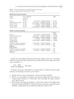
Figure 5.16 RAB Modification – Network Element Viewpoint
112 TDD Procedures
6. Node B notifies SRNC that modification preparation is ready (Radio Link Recon-
figuration Ready).
7. NBAP message Radio Link Reconfiguration Commit is sent from SRNC to Node
B with the activation time (if a ‘synchronized’ procedure).
8. RRC message Radio Bearer Reconfiguration is sent by SRNC to UE using RLC in
AM or UM mode. The Radio Bearer Reconfiguration Message includes parameters
related to Transport Channels, Physical Channels, etc. They include RRC Trans-
action Identifier, RRC State Indicator, RLC Size, MAC Logical Channel Priority,
Reconfigured UL/DL Transport Channel Information (Type, Channel Identity, TFS),
and Physical Channel Information. The activation time is also sent if of a synchro-
nized procedure.
9. Both UE and Nodes B actualize modification of DCH (i.e. apply a new trans-
port format).
10. UE sends RRC message Radio Bearer Reconfiguration Complete to SRNC.
11. SRNC acknowledges the modification of radio access bearer (Radio Access Bearer
Assignment Response)toCN.
In Figure 5.17, we illustrate the Radio Bearer Reconfiguration as implemented by the
various Radio Interface Protocol entities in the UTRAN and the UE [3]. After the receipt
of a RADIO BEARER RECONFIGURATION from the RNC-RRC (acknowledged or
unacknowledged transmission optional for the network), the UE executes the modifications
on L1 and L2. Upon receipt of a RADIO BEARER RECONFIGURATION COMPLETE
message from the UE-RRC, the NW-RRC executes the modifications on L1 and L2.
Finally, the old configuration, if any, is released from Node B-L1.
As a variation, the configuration of network side L1, MAC, etc. may be performed
prior to receiving the COMPLETE message, so that the UTRAN is ready to receive any
data that UE may send immediately following the sending of the COMPLETE message.
Note that Radio Bearer Reconfiguration involves, in general, reconfiguration of Trans-
port Channel and Physical Channel parameters. However, in some cases, it is useful to
reconfigure only the Transport or Physical Channels. An example scenario is when there
is excessive interference in the assigned timeslot, which could be reduced by changing
the timeslot for the physical channel. In this case, a simple Physical Channel Reconfig-
uration procedure may be invoked without involving the CN, rather than a full-blown
Radio Bearer reconfiguration procedure.
In the following, we illustrate an example of a procedure for a switch from common
channels (CELL
FACH) to dedicated (CELL DCH) channels [3]. In the UE the traffic
volume measurement function decides to send a MEASUREMENT REPORT message to
the network. (The network configures whether the report should be sent with acknowl-
edged or unacknowledged data transfer.) In the network, this measurement report could
trigger numerous different actions. For example the network could do a change of trans-
port format set, channel type switching or, if the system traffic is high, no action at all.
In this case a switch from CELL
FACH to CELL DCH is initiated.
First, the modifications on L1 are requested and confirmed on the network side with
CPHY-RL-Setup primitives. The RRC layer on the network side sends a PHYSICAL
CHANNEL RECONFIGURATION message to its peer entity in the UE (acknowledged or
unacknowledged transmission optional to the network). This message is sent on DCCH/L
RAB/RB Management Procedures 113
UE-RRC UE-RLC UE-MAC UE-L1 Node B-L1
Uu Iub
CPHY-RL-Modify-CNF
CRLC-Config-REQ
CRLC-Config-REQ
RLC-Data-REQ
RLC-Data-CNF
RLC-Data-IND
SRNC-MAC
SRNC-RLC SRNC-RRC
CRNC-MAC
CPHY-RL-Modify-REQ
CPHY-TrCH-Config-REQ
DCCH: Data ack
[Radio Bearer Reconfiguration Complete]
DCCH: Acknowledged Data
CMAC-D/C/SH-Config-REQ
CPHY-RL-Modify-REQ
CPHY-TrCH-Config-REQ
[Radio Bearer Reconfiguration Complete]
[Radio Bearer
Reconfiguration Complete]
CMAC-C / SH-Config-REQ
CMAC-D-Config-REQ
DCCH: RADIO BEARER RECONFIGURATION (acknowledged or unacknowledged optional)
Figure 5.17 RB Reconfiguration – Radio Interface Protocol Viewpoint
114 TDD Procedures
mapped to FACH/T. The message includes information about the new physical channel,
such as codes and the period of time for which the DCH is activated (This message
does not include new transport formats. If a change of these is required due to the
change of transport channel, this is done through the separate procedure Transport Channel
Reconfiguration.)
When the UE has detected synchronization on the new dedicated channel, L2 is
configured on the UE side and a PHYSICAL CHANNEL RECONFIGURATION COM-
PLETE message can be sent on DCCH/L mapped on DCH/T to RRC in the network, see
Figure 5.18. Triggered by either the NW CPHY
sync ind or the L3 complete message,
the RNC-L1 and L2 configuration changes are executed in the NW.
As stated before, the configuration of network side L1, MAC, etc. may be performed
prior to receiving the COMPLETE message, so that the UTRAN is ready to receive any
data that UE may send immediately following the sending of the COMPLETE message.
5.9 POWER CONTROL PROCEDURES
Power Control is used to adjust the transmit power of both UE and Node B in order
to achieve a desired Quality of Service with minimum transmit power, thus limiting the
interference level within the system.
Power Control is useful for both Downlink and Uplink, although the reasons are dif-
ferent. In the Uplink direction, Power Control is useful – and necessary – to counter the
near–far problem and to conserve the battery power consumption. The near-far problem
refers to the signal received by BS from a Far user experiencing excessive interference
from the signal received from a Near user. By decreasing the transmit power of the Near
user, the excessive interference can be reduced to normal levels. In the Downlink direc-
tion, however, there is no Near–Far problem. Assuming that transmitted signals to a Near
and a Far User have equal power, the signal received by the Near User will have equal
powers of the desired signal and the interfering signal. Moreover, all DL transmitted sig-
nals are Orthogonal at BS (although some of it may be lost by the time they arrive at the
UE due to multipath). Therefore, the reason for PC is to overcome effects of interference
from neighboring BSs.
As previously stated, the purpose of Power Control is to achieve a desired QoS by
adjusting the transmitted power. The desired QoS is measured in terms of block error rate
(BLER) at the Physical layer. The BLER requirements at the Transport Channel level
are translated into SIR per CCTrCH and the transmitted power is controlled in order to
maintain a desired SIR in the ways described below:
• Inner and Outer Loop PC: The transmit power level of UL and DL dedicated physical
channels are dynamically controlled based on QoS measurements. Their power control
can be divided into two processes operating in parallel: inner loop power control and
outer loop power control.
The objective of the inner loop PC is to keep the received SIR of the DPCHs assigned
to a CCTrCH as close as possible to a target SIR value for the CCTrCH, while the
outer loop PC is used to keep the received BLER of each TrCH within the CCTrCH as
close as possible to its target quality BLER. The outer loop PC provides a target SIR
per CCTrCH to be used for the inner loop.
Power Control Procedures 115
UE-RRC UE-RLC UE-MAC UE-L1 Node B-L1
Uu Iub
Switch
decision
Start tx/rx
Start tx/rx
CPHY-Sync-IND
Establish L1 connection
SRNC-MAC SRNC-RLC SRNC-RRCCRNC-MAC
CMAC-measurement-IND
CPHY-RL-Setup-REQ
DCCH: RACH: MEASUREMENT REPORT (acknowledged or unacknowledged RLC transmission configurable by UTRAN)
DCCH: FACH: PHYSICAL CHANNEL RECONFIGURATION (acknowledged or unacknowledged RLC transmission optional)
CPHY-RL-Setup-REQ
CPHY-Sync-IND
CMAC-D/C/SH-Config-REQ
CRLC-Config-REQ
DCCH: DCH: PHYSICAL CHANNEL RECONFIGURATION COMPLETE
CMAC-C/SH-Config-REQ
CRLC-Config-REQ
CMAC-D-Config-REQ
CPHY-RL-Setup-CNF
Figure 5.18 Physical Channel Reconfiguration – Radio Interface Protocol Viewpoint
116 TDD Procedures
The inner loop works on a frame-by-frame basis whereas the outer loop works on a
longer time scale.
• Closed and Open Loop PC: Closed Loop PC refers to a control process, which involves
both the UE and the UTRAN with power control information being fed back between
the UE and the UTRAN. On the other hand, Open Loop PC refers to a process where
the power is controlled autonomously by either the UE or the UTRAN, for UL or DL
power control respectively.
• Channel Pairing for Closed Loop PC: Since Closed Loop PC requires feedback between
the UE and the UTRAN, a feedback transport channel must be paired with the CCTrCH
that is being power controlled. For example, Closed Loop PC for a DL CCTrCH will
require a paired UL CCTrCH to send the feedback information. Although it is simpler
to pair a power-controlled CCTrCH and a feedback CCTRCH, it is sometimes more
efficient to share the feedback CCTrCH for multiple power controlled CCTRCHs.
• DL PC: The principles of DL transmit power control are shown in Figure 5.19. As
shown in Figure 5.19, the inner loop is a closed loop technique, whereas the outer
loop is an open loop technique. Open loop techniques are possible because the uplink
and downlink share the same frequency band, so that radio channel characteristics
are reciprocal.
In the inner loop, the UE performs SIR measurement of each DL DPCH assigned to
a DL CCTrCH and compares the measured SIR with the target SIR for the CCTrCH in
order to generate power control commands that are transmitted to Node B. Then Node
B receives these commands and adjusts its transmit power up or down accordingly.
In the outer loop, the UE adjusts the target SIR autonomously (i.e. open loop) based
on CRC check measurements (which are an indication of BLER).
• Initialization: For each dedicated DL CCTrCH, the SRNC provides initial power control
parameters (including target BLER and Step size) to the UE via RRC signaling and
to Node B via internal UTRAN signaling. The UE outer loop sets the initial target
SIR based on the initial parameters received. Figure 5.20 shows the sequence of events
involved in DL Power Control.
DPCH
Measurement
BLER
SIR
Power
Amplifier
DL DPCH / CCTrCH
Target BLER
TPC Step-Size
TPC Bits
UE BS/Node B RNC
Radio
Interface
DPCH
Measurement
Target SIR
Outer Loop
Algorithm
Inner Loop
Algorithm
UL DPCH
Inner Loop PC
Commands
Inner Loop
Algorithm
Initial Power
TPC Step-Size
Initialization
Algorithm
Figure 5.19 Downlink Power Control Scheme
Power Control Procedures 117
UE
RADIO LINK SETUP REQUEST
RADIO LINK SETUP RESPONSE
Node B CRNC SRNC
Compare
Estimated and
Target SIR
TPC Commands
Inner Loop Power
Control
RADIO LINK SETUP REQUEST
(TPC Step Size, UL/DL CCTrCH, Pairing
Timeslot ISCP, Initial DL Tx Power,
Max DL Power, Min DL Power,
Rate Matching Attributes)
(TPC Step Size, UL/DL CCTrCH Pairing,
Rate Matching Attribute,Target BLER,
Timeslot ISCP, P-CCPCH RSCP)
(Max DL Power, Min DL Power)
RADIO LINK SETUP RE
SPONSE
RRC Messages for Radio Bearer
Setup, RB or TrCH or PhCH Reconfig
(TPC Step Size, UL/DL CCTrCH,
Pairing, Target BLER, Rate Matching
Attributes)
Compare
Estimated and
Target SIR
Estimate BLER
and Update
Target SIR, if
needed.
TPC Commands
Outer Loop Power
Control
Figure 5.20 Downlink Power Control Procedure
• Uplink PC: The principles of Uplink power control are depicted in Figure 5.21. Clearly,
the outer loop PC uses a closed loop technique, because it involves a feedback mech-
anism between UTRAN and the UE. In contrast, the inner loop PC uses an open loop
technique, because it is self-contained within the UE.
For dedicated channels, the uplink power control outer loop is mainly the respon-
sibility of the SRNC. For each dedicated UL CCTrCH, an initial value of target SIR
(determined by the CRNC and passed to the SRNC) is provided to the UE (via RRC
signaling) when the CCTrCH is first established. The SRNC then updates the target
SIR based on measurement of uplink CCTrCH quality. CCTrCH quality is defined by
the quality (BLER) of the CCTrCH’s transport channels. TrCH BLER is calculated by
the SRNC based on the physical layer CRC results of the transport channels. The CRC
results are passed from Node B to the SRNC via the Iub and Iur interfaces as part of
the frame protocol. Updated target SIR is signaled by the SRNC (via RRC signaling)
to the UE whenever an outer loop update occurs.
The UE’s inner loop measures the serving cell’s PCCPCH/P RSCP each frame and
calculates the pathloss between Node B and the UE. Based on the pathloss, UTRAN
118 TDD Procedures
DL-Pathloss
Measurement
Outer Loop
Algorithm
BLER
DL-PL
Target SIR
UL Physical Channel Control
Power
Adjustment
UE BS/Node B RNC
Radio
Interface
P-CCPCH
Inner Loop
Algorithm
Power
Amplifier
UL DPCH
Target SIR
DPCH
Measurement
Initial Target
SIR
Initialization
Algorithm
Figure 5.21 Uplink Power Control Scheme
0 121110982 3 4 5 6 71 1413 0 82 3 4 5 6 71
B U B U
U
PS
U
PS
B = P-CCPCH or other beacon
U = Uplink
PS = Power Setting
n-th frame
(n+1)-th frame
Figure 5.22 Working of the Inner Loop Uplink Power Control
signaled values of UL Timeslot interference, and UTRAN-signaled target SIR, the UE
calculates its transmit power. Figure 5.22 illustrates the inner loop PC concept. The
PCCPCH measurements are done in timeslot 2 and used to set the power levels of the
two uplink timeslots 3 and 9.
• PC for Common Channels: In DL, the transmit power level of the PCCPCH and
SCCPCH, respectively, is determined by the C-RNC during cell setup process, and can
be changed based on network determination on a slow basis. Specifically, the power of
PCCPCH (broadcast channel) is a constant and can range from −15 to +40 dBm. The
powers of Primary SCH, Secondary SCH, PCH, PICH and FACH are specified individ-
ually relative to the PCCPCH power. The power of RACH is controlled dynamically
using the Open Loop technique.
UE Timing Advance Procedures 119
5.10 UE TIMING ADVANCE PROCEDURES
In large cells, the propagation delay between a UE and Node B may vary considerably
depending on the location of the UE. In such a case, the UTRAN may decide to apply
the so-called Timing Advance Procedure. Essentially, the UTRAN commands each UE to
advance its transmission relative to its own timing reference, so that, after the propagation
delay, all UE transmissions are aligned in time when received by Node B [1].
Figure 5.23 illustrates the Timing Advance concept. Recall that the Network transmits
(marked as NW-TX in the figure) the SCH pulses, which are offset by T-offset from
the timeslot boundary, see also Chapters 3 and 4. This SCH pulse is received by the UE
(marked as UE-RX in the figure) after certain propagation delay. Based on the measured
SCH pulse, the UE estimates the T-offset and hence the Timeslot Boundary. In order
to compensate for the propagation delay, UE advances the estimated Timeslot Boundary
by 2
∗
Estimated Propagation Delay. Now, UE transmissions which start at its local time-
advanced Timeslot Boundary will arrive at the Network after a propagation delay, so that
they are aligned with the Timeslot Boundary at the network.
Whether or not Timing Advance is enabled in a c ell is broadcast on BCCH/L. Typically,
the Timing Advance is enabled in all but pico-cell environments where the limited distance
T offset
NW-TX
SCH-Transmissions
UE-RX
UE -TX with TA
TA = 2× Propagation Delay
NW-RX with TA
Propagation Delay
Estimated Timeslot
Boundary
Timeslot BoundaryTimeslot Boundary
Propagation Delay
Figure 5.23 UE Timing Advance Concept
120 TDD Procedures
between UE and Node B/cell does not introduce propagation delays significant enough
to require it.
The initial value for timing advance (TA
phys
) will be determined in the UTRAN by
measurement of the timing of the PRACH/P. The required timing advance is represented
as a 6-bit number (0–63) ‘UL Timing Advance’ TA
ul
, being the multiplier of 4 chips,
which is nearest to the required timing advance (i.e. TA
phys
= TA
ul
× 4 chips).
When Timing Advance is used, the UTRAN will continuously measure the timing of
a transmission from the UE and send the necessary timing advance value to the UE.
On receipt of this value, the UE will adjust the timing of its transmissions accordingly
in steps of ±4 chips. The transmission of TA values is done by means of higher layer
messages. Upon receiving the TA command, the UE will adjust its transmission timing
according to the timing advance command at the frame number specified by higher layer
signaling. The UE is signaled the TA value in advance of the specified frame activation
time to allow for local processing of the command and application of the TA adjustment
on the specified frame. Node B is also signaled the TA value and radio frame number
that the TA adjustment is expected to take place.
5.10.1 Initial Timing Advance
Initialization refers to the establishment of the first Timing Advance behavior for a given
UE when establishing a USCH or DCH connection. In the initial RACH burst, there is
no application of Timing Advance but it is provided from then on subsequent USCH or
DCH bursts. The initial value for the Timing Advance is determined from one or more
measurements of Time Delay (TD) of the RACH burst, and signaled to, and implemented
in the UE Layer 1 prior to the commencement of user plane traffic. Figure 5.24 shows
the block level representation of the RACH burst transmission, Timing Deviation (TD)
measurement, and initial TA computation. Omitted for the sake of simplicity is the RNC
signal back to the Node B of Timing Advance signaled to the UE.
UE Node B
RNC
RRC CONNECTION REQ over RACH [1]
Measure
TD
[1]
RACH Data and TD measurement [1]
TA
Computation
[2]
RRC CONNECTION SETUP over FACH [3]
TDD Timing Advance Payload [3]
TA update
[5]
Figure 5.24 Initial TA Procedure
UE Timing Advance Procedures 121
The following details the steps involved in the Initial Timing Advance procedure:
1. The UE signals a RRC CONNECTION REQ over the CCCH/L logical channel over
RACH/T. Node B measures TD from the RACH burst. The TD measurement passes
from Layer-1 in Node B, through MAC-c/sh in the RNC to the RRC.
2. The RRC in the RNC performs the Timing Advance Calculation.
3. Assuming RRC Connection establishment on DCH, the SRNC executes a Radio Link
Setup procedure with Node B, and then the SRNC RRC sends an RRC CONNECTION
SETUP message to the UE over FACH/T. This signal contains the Timing Advance
information including the CFN for activation. The information is also forwarded to the
Layer 1 in the Node B via the frame protocol for possible use.
4. The UE RRC passes the Timing Advance to Layer 1 with the CFN activation time.
5. Layer 1 implements the new Timing Advance if the CFN value is within an acceptable
range. Establishment of the user plane may now be performed and the steady-state
scenario becomes applicable.
5.10.2 Steady-State Timing Advance
The steady-state condition is said to exist for a UE, which is in the Cell
DCHstate or
Cell FACH state with USCH/T. Such a UE would have a continuous or regular exchange
of data over the air. Figure 5.25 illustrates the TD measurement and TA update signaling
flows for DCH/T and USCH/T channels. Note that the TD is carried apart from the uplink
data for DCH/T and together with the data for USCH/T. Not shown in the figure is the
additional fact that the computation of the TA is performed in the SRNC for DCH/T and
in the CRNC for USCH/T. Also omitted for the sake of simplicity is the RNC signal back
to Node B of Timing Advance signaled to the UE.
The following details the steps involved in the Steady-State Timing Advance procedure:
1. A USCH or uplink DCH transmission from the UE causes the TD to be measured in
Node B. For USCH, the TD and an indication of the associated UE are passed on to
the CRNC RRC along with the PDU via the MAC-c/sh. For DCH, the TD is passed
separately from the DCH Data directly to the SRNC RRC without MAC intervention.
2. For USCH/T, the MAC-c/sh processes TD measurements in accordance with the cri-
teria set forth by the RRC. For example, a threshold reporting could be used. That
is, when the TD is outside a window imposed by the RRC, indicating a significant
change in the two-way propagation delay time since the last Timing Advance update,
the MAC-c/sh sends a CMAC
MEASUREMENT IND to the RRC.
3. For both USCH/T and DCH/T, the RRC performs the Timing Advance Computation.
4. The Timing Advance Computation results are forwarded through RRC peer-to-peer
signaling to the RRC in the UE (for example, Physical Channel Reconfiguration,
Transport Channel Reconfiguration, Radio Bearer Reconfiguration or Uplink Physi-
cal Channel Control). The same information is also sent to Layer 1 in Node B for
possible use.
5. Within the UE, RRC Inter-layer primitive CPHY
CONFIG REQ indicates the new
Timing Advance and the CFN when the new value is to take effect in Layer 1. The
Timing Advance is appropriately applied by Layer 1 for all future uplink transmissions.
122 TDD Procedures
UE Node-B
RNC
USCH transmission [1]
Measure
TD
USCH Data and TD measurement [1]
DCH transmission [1]
Measure
TD
DCH Data [1]
TD measurement [1]
TA
Computation
[3]
PHYSICAL CHANNEL RECONFIGURATION [4]
TDD Timing Advance Payload [4]
TA update
[5]
Figure 5.25 Steady-State Timing Advance Procedure
For the above procedure to work properly, it is imperative that uplink transmissions and
the resulting TD measurements occur sufficiently frequently and thus prevent the UE from
traveling a distance which would cause the burst to occur outside of the channel and data
estimation windows.
5.11 MEASUREMENTS PROCEDURES
Measurements are performed and reported by the UE and Node B at the request of RNCs,
although certain measurements are performed autonomously by the UE and Node B.
For all the UEs in a cell, the CRNC can request the set-up, modification and release
of measurements via System Information (SIB 11 and SIB 12) broadcast on the BCH/T.
For a specific UE, the SRNC can request measurements via the MEASUREMENT CON-
TROL message. (We shall refer to these measurements as Common-UE Measurements
and Specific-UE Measurements respectively.) UEs perform measurements in all modes
and states, but report measurements only in CELL
FACH and CELL DCH states.
For Node B, the CRNC can request general measurements applicable to a cell or group
of cells or a Node-B, called ‘Common Measurements’. The CRNC or the SRNC can
also request measurements that apply to a specific UE, collectively called ‘Dedicated
Measurements’.
Measurements Procedures 123
UE
C-RNC
S-RNC
Node B
Measurement Control (RRC) DCCH/L:FACH/T
(Traffic Volume Measurement-for RB Setup)
Measurement Report (RRC) DCCH/L:RACH/T
(ISCP, PCCPCH RSCP, Traffic Volume)
Common Measurement Report (NBAP)
(ISCP, Carrier Power etc)
Common Measurement Initiation Request (NBAP)
(Carrier Power, ISCP etc)
Dedicated Measurement Initiation Request (NBAP)
(UL SIR-for power control only)
Dedicated Measurement Initiation
Request (RNSAP)
(UL SIR-for power control only)
CELL_FACH
Measurement at UE
ISCP, PCCPCH
RSCP
Measurement at
Node-B
ISCP, Carrier power
Common Measurement Configuration
Node B Common Measurement
Control
Node B Dedicated Measurement
Control
Configure dedicated Node B
measurements for power control
UE Measurement Control
Configure UE measurements
Node-B Common
Measurements
UE-Specific
Measurements
Node-B Dedicated
Measurements
Figure 5.26 Example UE and Node B Measurement Procedures
Figure 5.26 depicts example procedures for Node B and UE measurement procedures.
5.11.1 Common UE Measurements
As mentioned earlier, UEs perform general system related measurements, the information
about which is broadcast on SIB 11/12. Figure 5.27 shows the details.
5.11.2 Specific UE Measurements
Figure 5.28 shows how the Measurement Control Message can specify measurements to
be performed by a specific UE.
5.11.3 Measurement Types
As shown in Figure 5.28 and Figure 5.29, the measurements can be of the following types:
1. Intra-frequency measurement.
2. Inter-frequency measurement.
124 TDD Procedures
SIB 11/12
Use of HCS
Cell selection
and reselection
quality measure
Measurment Control
System Information
Intra-frequency
measurement
system info
Inter-frequency
measurement
system info
Inter-RAT
measurement
system info
Traffic volume
measurement
system info
UE Internal
measurement
system info
Figure 5.27 UE Measurement Control System Information
MEASUREMENT CONTROL
message
Measurement
Identity
Measurement
Command
Measurement
Reporting mode
CHOICE of
Additional
measurements
- Setup or
- Modify or
- Release
Ack/Unack mode
Periodic/Event
list of1 4
-measurement ID
1 16
Intra-frequency
measurement
Inter-frequency
measurement
Inter-RAT
measurement
UE Positioning
measurement
Trafic volume
measurement
Quality
measurement
UE Internal
measurement
Figure 5.28 UE Measurement Control by Dedicated Signaling
Hysteresis
Measurement
quantity-RSCP
Time
PCCPCH/P1
PCCPCH/P2
Reporting
event 1G
Figure 5.29 Hysteresis Parameter for Measurements
Measurements Procedures 125
3. Inter-RAT measurement.
4. Traffic volume measurement.
5. Quality measurement.
6. UE internal measurement.
7. UE positioning measurement.
Table 5.1 shows which of these measurements are applicable in various UE states.
Table 5.1 also delineates the specific measurements involved in each of these measure-
ment sets. Some of these are now defined briefly:
• PCCPCH/P RSCP (Received Signal Code Power): The received power on PCCPCH/P
of serving or neighbor cell. The reference point for the RSCP is the antenna connector
at the UE.
• Pathloss: This is based on the PCCPCH/P RSCP of the serving cell and the PCCPCH/P
TX power, which is broadcast in SIB 5. It is defined as: Pathloss (in dB) = PCCPCH/P
TX Power – PCCPCH/P RSCP.
• Timeslot ISCP (Interference Signal Code Power): The interference on the received
signal in a specified timeslot measured on the midamble. The reference point for the
ISCP is the antenna connector at the UE.
• SFN-SFN Observed Time Difference: This is the time difference of the reception times
of frames from two cells (serving and target) measured in the UE and expressed in
chips. It is divided into two types. Type 2 applies if the serving and the target cell have
the same frame timing.
• Traffic Volume: This is typically measured for non-real-time services and consists of
measuring the amount of data in RLC buffers, its average value and its variance.
• TrCh BLER: This is an estimation of the transport channel block error rate (BLER),
based on evaluating the CRC on each transport block.
• GSM RSSI (Received Signal Strength Indicator): This is the wideband received power
of a GSM BCCH carrier within the relevant channel bandwidth in a specified timeslot.
The reference point for the RSSI is the antenna connector at the UE.
• UTRAN RSSI (Received Signal Strength Indicator): This is the wideband received
power of a UTRAN DL carrier within the relevant channel bandwidth in a specified
timeslot. The reference point for the RSSI is the antenna connector at the UE.
• CCTrCH SIR (Signal to Interference Ratio): This is defined as: (RSCP/ISCP)xSF,
where SF is the Spreading Factor and RSCP and ISCP are as per definitions above.
The reference point for the SIR is the antenna connector of the UE
• UE Transmitted Power: The total UE transmitted power on one carrier measured
in a timeslot. The reference point for the UE transmitted power is the UE antenna
connector.
5.11.4 Measurement Reporting Methods
The Measurement Control Message also specifies the method of measurement reporting.
This can be either periodic or event triggered. In the periodic case, the amount of reporting
and a reporting interval are specified. In the triggered case, a number of parameters are
used to define the trigger event. They include a threshold, hysteresis, time-to-trigger.
Figures 5.29 and 5.30 illustrate some of these concepts.
126 TDD Procedures
Table 5.1 UE States and Applicable Measurement Types
Connected Mode
Measurement Type Idle Mode Cell
−
PCH/URA
−
PCH Cell
−
FACH Cell
−
DCH
Intra-frequency
measurement
• PCCPCH/P RSCP (1)
• Pathloss
• PCCPCH/P RSCP (1)
• Pathloss
• PCCPCH/P RSCP(1)
• Pathloss
• Timeslot ISCP
• SFN-SFN Observed Time
Difference
• PCCPCH/P RSCP (1)
• Pathloss
• Timeslot ISCP
• SFN-SFN Observed Time
Difference
Inter-frequency
measurement
• TDD PCCPCH RSCP (2)
• FDD CPICH RSCP and
CPICH Ec/Io
• TDD PCCPCH RSCP (2)
• FDD CPICH RSCP and
CPICH Ec/Io
• TDD PCCPCH RSCP (2)
• FDD CPICH RSCP and
CPICH Ec/Io
• TDD PCCPCH RSCP (2)
• FDD CPICH RSCP and
CPICH Ec/Io
Inter-RAT
measurement
• GSM BCCH carrier
strength
• GSM BCCH carrier
strength
• GSM BCCH carrier
strength
• GSM BCCH carrier
strength
Traffic volume
measurement
··· • Traffic Volume on any
UL DCH or USCH
(based on RLC Buffer
Payload)
• Traffic Volume on any
UL DCH, RACH or
USCH
(based on RLC Buffer
Payload)
• Traffic Volume on any
UL DCH, RACH or
USCH
(based on RLC Buffer
Payload)
Quality measurement ··· ··· ··· • DL TrCh BLER
• DL CCTrCh SIR
UE internal
measurement
··· ··· ··· • Transmitted Power
• Applied Timing Advance
UE positioning
measurement
··· ··· ··· • Positioning method etc.
(1) of Serving Cell & Neighbor Cells broadcast on SIB 11/12
(2) 3.84 or 1.28 Mcps
Cell/URA Update Procedures 127
ISCP
Threshold
Time-to-trigger
Time-to-trigger
No report (as measurement
is below threshold)
Event report
Time
Timeslot
ISCP
Figure 5.30 Use of Time-to-Trigger Parameter
5.11.5 Node B Measurements
As mentioned at the beginning of the section, CRNC/SRNC can request Node Bs to
perform Common and/or Dedicated measurements. The following are the types of mea-
surements:
• Common measurement types:
• Transmitted carrier power
• Received total wideband power
• UL timeslot ISCP
• Load
• SFN-SFN observed Time Difference
• UTRAN GPS Timing.
• Dedicated measurement types:
• Transmitted code power
• RSCP
• SIR
• Rx Timing Deviation.
As with UE measurements, these measurements can be reported periodically or triggered
by an event.
5.12 CELL/URA UPDATE PROCEDURES
A cell or URA update procedure may be triggered in a variety of contexts. An example
is when the UE moves into a new cell/URA in connected mode states CELL
FACH/
CELL
PCH/URA PCH. The new cell or URA may be connected to the same or different
Node-B, same or different SRNC. If the associated RNC changes, the procedure involves
128 TDD Procedures
UE Source RNC
CN
Target RNC
[new C
-
RNTI,
D
-
RNTI, UL message]
1.
CCCH
: Cell Update
[Cell Update Cause, U-RNTI,
Measured results on PRACH]
RRC-relay
RRC
RNSAP RNSAP
4.
DCCH
: Cell Update Confirm
[S
-
RNTI,SRNC
-
ID
,
new S
-
RNTI
,
new SRNC
-
ID, new C-RNTI]
RRC
RRC
5.
DCCH
: UTRAN Mobility Information Confirm
RRCRRC
3. Serving RNC Relocation
2. Uplink Signaling
Transfer Indication
Figure 5.31 Cell Update with SRNS Relocation
the so-called ‘SRNS relocation’. It is also possible not to switch to the new SRNC, but
to keep the connection to the old SRNC via the new RNC (now referred to as a Drift
RNC). In this case, SRNS relocation is not needed as part of this procedure.
Shown in Figure 5.31 is an example of Cell Update due to cell reselection involving
SRNC relocation. The steps involved in a Cell Update are as follows:
1. UE sends a RRC message ‘Cell Update’ to the UTRAN, after having performed cell
re-selection. Upon reception of a CCCH message from a UE, target RNC allocates a
C-RNTI for the UE.
2. Controlling target RNC forwards the received message via Uplink Signaling Trans-
fer Indication RNSAP message towards the SRNC. Message includes, besides target
RNC-ID, also the allocated C-RNTI, which is to be used as UE identification within
the C-RNC, and the D-RNTI. Upon receipt of the RNSAP message SRNC decides to
perform SRNS Relocation towards the target RNC.
3. Serving RNS relocation procedure is executed (see later section), after which, the target
RNC allocates new S-RNTI for the UE and becomes the new serving RNC.
4. Target RNC responds to UE by RRC Cell Update Confirm, including old S-RNTI
and SRNC-ID as UE identifiers. Message contains also the new S-RNTI, SRNC-ID
and C-RNTI.
5. UE acknowledges the RNTI reallocation by sending the RRC message UTRAN Mobil-
ity Information Confirm.
Shown in Figure 5.32 is an example of URA Update without SRNC relocation. Here, the
target RNC and serving RNC are located separately from each other. The steps involved
in a URA Update without SRNC relocation are:
Cell/URA Update Procedures 129
UE
5.
CCCH
: URA Update Confirm
2. Uplink Signaling Transfer Indication
1.
CCCH
: URA Update
[U
-
RNTI, URA update cause]
RRC-relayRRC
RRC
RNSAP
RNSAP
RNSAP
4. Downlink Signaling Transfer
Request
RNSAP
Target
RNC
RRC-relay
[new C
-
RNTI
,
D
-
RNTI, UL message]
Serving
RNC
3. Decision Not to
perform SRNS
relocation
Figure 5.32 URA Update without SRNC Relocation
1. UE sends a RRC message URA Update to the UTRAN, after having made cell re-
selection and determining that URA has changed.
2. Upon receipt of the message from a UE, Target RNC decodes the RNC ID and the
S-RNTI. Since the UE is not registered in the target RNC, the target RNC allocates C-
RNTI and D-RNTI for the UE. The Target RNC forwards the received message towards
the SRNC by RNSAP Uplink Signaling Transfer Indication message. The message
includes also the cell-ID from which the message was received and the allocated
C-RNTI and D-RNTI.
3. Upon receipt of the RNSAP message SRNC decides not to perform an SRNS
relocation towards the target RNC. The target RNC become C-RNC while SRNC
remains unchanged.
4. SRNC sends to the Target RNC a Downlink Signaling Transfer Request,which
includes a URA Update Confirm message.
5. The URA Update Confirm is forwarded to the UE (via CCCH with new RNTIs) from
the target RNC.
Figure 5.33 shows the Cell Update procedure as seen between the various protocol layers
of the Radio Interface (Inter-Layer Procedure).
The cell update procedure is triggered by the cell re-selection function in the UE, which
notifies which cell the UE should switch to. The UE reads the broadcast information of
the new cell. Subsequently, the UE RRC layer sends a CELL UPDATE message to the
UTRAN RRC via the CCCH/L logical channel and the RACH/T transport channel. The
RACH transmission includes the current U-RNTI (S-RNTI and the SRNC Identity).
Upon receipt of the CELL UPDATE, the UTRAN registers the change of cell. If the
registration is successful it replies with a CELL UPDATE CONFIRM message transmitted
on the DCCH/FACH to the UE. The message includes the current U-RNTI (S-RNTI
and SRNC Identity) and it may also include new C-RNTI and/or U-RNTI (S-RNTI +
SRNC Identity).
130 TDD Procedures
CPHY-RL-Release-REQ (Stop RX and TX)
[Cell Update]
CCCH: RACH: CCCH Message
[Cell Update
Confirm]
UE-RRC UE-MAC
UE-L1
Node B-MAC
RNC-L1
CRNC-MAC SRNC-RRC
Uu Iub
SRNC-MAC
CPHY-RL-Setup-REQ (Start RX)
CPHY-Sync-IND
BCCH :BCH:Message
[System info]
MAC-B-Data-IND
[New system info]
CPHY-RL-Setup-REQ (Start TX)
MAC-D-Data
-REQ
[Cell Update
Confirm]
DCCH: FACH: DCCH Message
[Cell Update Confirm]
[Cell Update
Confirm]
MAC-C/SH-
Data-REQ
Iur
UE-RLC
RLC-TM-Data
-REQ
[Cell Update]
RLC-TM-Data
-REQ
[Cell Update
Confirm]
MAC-D-Data
-IND
[Cell Update
Confirm]
Cell reselection
triggered
[Cell Update]
RLC-TM-Data
-IND
SRNC-RLC
MAC-C/SH-
Data-REQ
Register
change of
cell
Figure 5.33 Inter-Layer Procedure for Cell Update
5.13 HANDOVER PROCEDURES
Handover is an essential function to guarantee user mobility and service QoS. As a user in
CELL
DCH state moves from one cell to another, th e network automatically transfers the
user connection to a channel in the new cell, releasing the channel in the old cell. (In all
other Connected Mode states, user mobility is handled by the Cell Reselection function.)
There are various types of handovers, including:
1. Inter-cell Intra-frequency handover.
2. Inter-Cell Inter-frequency handover.
3. Inter-RNS handover (with or without SRNS relocation).
4. Inter-mode (TDD <- > FDD) handover.
5. Inter-RAT (UMTS <-> GSM) handover.
There are two different techniques of handover: hard handover and soft handover. A
hard handover is characterized by the UE commencing communications with a new cell
after terminating communications with the old cell. A soft handover occurs when the
UE communicates with a new cell without interrupting communications with the current
serving cell. TDD only supports hard handovers.
Figure 5.34 illustrates hard handovers of type 1, 2 and 3.
Handover Procedures 131
(i)
N/Ap1
SRNS
UTRAN
CN(UMTS)
SRNC
Node
B
Node
B
(ii)
(b) Inter-Node B (Intra-RNS)
SRNS
UTRAN
CN(UMTS)
SRNC
Node
B
Node
B
N/Ap1
(i)
(ii)
(a) Inter-Cell (Intra-Node-B)
SRNS
UTRAN
CN(UMTS)
SRNC
Node
B
Node
B
N/Ap1
CN(UMTS)
Node
B
Node
B
N/Ap1
SRN
C
SRN
S
UTRA
N
(c) Inter-RNS (Intra-UTRAN)
No Iur - Handover with SRNS relocation
SRNS
UTRAN
RNS
CN(UMTS)
SRNC RNC
N/Ap1
(i)
(d) Inter-RNS (Intra-UTRAN)
Iur
-
Handover without SRNS relocation
SRNS
UTRAN
RNS
CN(UMTS)
SRNC RNC
N/Ap1
N/Ap2
(i)
Node
B
Node
B
Node
B
Node
B
UTRAN
SRNS
RNS
CN(UMTS)
RNC SRNC
N/Ap1 N/Ap 2
(ii)
Node
B
Node
B
Node
B
Node
B
UTRAN
DRNS
SRNS
CN(UMTS)
SRNC DRNC
N/Ap1 N/Ap2
(ii)
Node
B
Node
B
Node
B
Node
B
Node
B
Node
B
Node
B
Node
B
N/Ap2
Figure 5.34 Handover Types
132 TDD Procedures
(e) Inter-RNS (Intra-UTRAN)
Iur - Handover with SRNS Relocation
SRNS
UTRAN
DRNS
CN(UMTS)
SRNC DRNC
N/Ap1
N/Ap2
(i)
Node
B
Node
B
Node
B
Node
B
UTRAN
DRNSSRNS
CN(UMTS)
SRNC DRNC
N/Ap1 N/Ap2
(ii)
Node
B
Node
B
Node
B
Node
B
UTRAN
SRNSRNS
CN(UMTS)
RNC SRNC
N/Ap1 N/Ap2
(iii)
Node
B
Node
B
Node
B
Node
B
Figure 5.34 (continued)
When a UE is in CELL DCH state, UTRAN (SRNC) controls the handover and decides
when it is needed. The UE will assist in the handover decision by providing measure-
ments of the radio environment it is experiencing, e.g. measurement reports reflecting
signal quality from current cell and neighboring cells. Based on the UE measurements,
the UTRAN makes a decision to initiate a handover. The handover procedure itself
includes additional decisions pertaining to the radio and terrestrial resources to be allo-
cated/released for a cell, when to stop and restart transmission of traffic radio bearers
and signaling radio bearers based on the service type (RT or NRT), and whether to use
transport channel or radio bearer reconfiguration to accomplish the handover. However,
there is normally only a reassignment of physical channels, with no effect on logical or
transport channels.
Figure 5.35 shows an example of a hard handover between two cells belonging to
different Node Bs and different RNCs. It is assumed that there is no SRNS relocation, so
that the UE is connected to the old SRNC via the new RNC via Iur interface.
The steps involved in an Inter-RNC handover procedure are as follows:
1. SRNC sends a Radio Link Setup Request message to the target RNC (i.e. new
RNC). Parameters: target RNC identifier, s-RNTI, Cell ID, Transport Format Set,
Transport Format Combination Set, DCH Information, etc.
Handover Procedures 133
RNSAPRNSAP
1. Radio Link
Setup Request
UE
Node B
Target
Node B
Source
RNC
Source
RNC
target
SRNC
RRC
RRC
12. DCCH: Physical Channel Reconfiguration Complete
RRC
7. DCCH: Physical Channel Reconfiguration
RRC
6. ALCAP Iur Data
Transport Bearer Setup
NBAP NBAP
2. Radio Link Setup Request
NBAP NBAP
3. Radio Link Setup Response
NBAP NBAP
14. Radio Link Deletion Request
NBAP NBAP
15. Radio Link Deletion Response
4. ALCAP Iub Data Transport Bearer Setup
16. ALCAP Iub Data Transport Bearer Release
RNSAP RNSAP
17. Radio Link Deletion Response
18. ALCAP Iur Data
Transport Bearer Release
RNSAPRNSAP
RNSAP
13. Radio Link Deletion Request
RNSAP
NBAP
NBAP
8. Radio Link Failure Indication
RNSAP
RNSAP
9. Radio Link Failure Indication
NBAP
NBAP
10.Radio Link Restore Indication
RNSAP
11. RL Restore
Indication
RNSAP
5. RL Setup
Response
Figure 5.35 Inter-RNC Handover Procedure (Peer-to-Peer Procedure)
2. The target RNC allocates RNTI and radio resources for the RRC connection and
the Radio Bearer(s) (if possible), and sends the NBAP message Radio Link Setup
Request to the target Node B. Parameters: Cell ID, Transport Format Set, Transport
Format Combination Set, frequency, Timeslots, User Codes, Power Control informa-
tion; DCH information, etc.
3. Node B allocates resources, starts PHY reception, and responds with NBAP mes-
sage Radio Link Setup Response. Parameters: Signaling link termination, Transport
134 TDD Procedures
layer addressing information for the Iub Data Transport Bearer, DCH information
response.
4. Target RNC initiates set-up of Iub Data Transport Bearer using ALCAP protocol.
The request for set-up of Iub Data Transport Bearer is acknowledged by Node B. A
separate transport bearer is established for the DCH.
5. When the Target RNC has completed the preparation phase, Radio Link Setup
Response is sent to the SRNC, including the DCH information parameters.
6. SRNC initiates set-up of Iur Data Transport Bearer using ALCAP protocol. Target
RNC acknowledges the request for set-up of Iur Data Transport Bearer. A separate
transport bearer is established for the DCH.
7. SRNC sends a RRC message Physical Channel Reconfiguration to the UE.
8. When the UE switches from the old RL to the new RL, the source Node B detects a
failure on its RL and sends a NBAP message Radio Link Failure Indication to the
source RNC (i.e. old RNC).
9. The source RNC sends a RNSAP message Radio Link Failure Indication to
the SRNC.
10. Target Node B achieves uplink sync on the Uu and notifies target RNC with NBAP
message Radio Link Restore Indication.
11. Target RNC sends RNSAP message Radio Link Restore Indication to notify SRNC
that uplink sync has been achieved on the Uu.
12. When the RRC connection is established with the target RNC and necessary radio
resources have been allocated, the UE sends RRC message Physical Channel Recon-
figuration Complete to the SRNC.
13. The SRNC sends a RNSAP message Radio Link Deletion Request to the
source RNC.
14. The source RNC sends NBAP message Radio Link Deletion Request to the source
Node B. Parameters: Cell id, Transport layer addressing information.
15. The source Node B de-allocates radio resources. Successful outcome is reported in
NBAP message Radio Link Deletion Response.
16. The source RNC initiates release of Iub Data Transport Bearer using ALCAP protocol.
The DSCH transport bearer is also released.
17. When the source RNC has completed the release, the RNSAP message Radio Link
Deletion Response is sent to the SRNC.
18. SRNC initiates release of Iur Data Transport bearer using ALCAP protocol. The
Source RNC acknowledges the request for release of Iur Data Transport bearer. The
DSCH transport bearer is also released.
Figure 5.36 illustrates some of the Inter-Layer messages involved in an example Inter-
Node B handover.
The SRNC will send the RSNAP Radio Link Addition message to the CRNC, which
will send a Node B Radio Link Setup Request message to the target Node B with Layer 1
(physical and transport channel) parameters for the new cell. A new transport data bearer is
also allocated on the Iub. The handover command is then sent to the UE via the appropriate
RRC message (e.g., PHYSICAL CHANNEL RECONFIGURATION). If ‘activation time’
is specified, the handover will be synchronized to occur at the specified CFN. Otherwise,
the handover can occur upon receipt of the message.
NAS Signaling Message Transmission Procedures 135
PHYSICAL CHANNEL RECONFIGURATION
UE RRC
RADIO LINK SETUP REQUEST
UE L1 CRNC RRC
CPHY_RL_Release_REQ
RADIO LINK SETUP RESPONSE
Iub Data Transport Bearer Setup
CPHY_RL_Release_CNF
CPHY_RL_Setup_REQ
CPHY_RL_Setup_CNF
CPHY_Cell_Search_REQ
CPHY_Execute
CPHY_Sync_IND
RADIO LINK RESTORE
RADIO LINK RESTORE
Stop old tx/rx
RADIO LINK ADDITION
RESPONSE
HO command is
triggered
‘New’
Node B
‘Old’
Node B L1
Stop old tx/rx
start new tx/rx
RADIO LINK DELETION
RESPONSE
RADIO LINK DELETION
REQUEST
RADIO LINK DELETION
REQUEST
RADIO LINK DELETION
RESPONSE
L1 synchronization
Start new tx/rx
RADIO LINK ADDITION
REQUEST
RL addition
triggered
SRNC RRC
PHYSICAL CHANNEL RECONFIGURATION COMPLETE
Figure 5.36 Inter-Node B Handover Procedure (Inter-Layer Procedure)
5.14 NAS SIGNALING MESSAGE TRANSMISSION
PROCEDURES
One of the purposes of the Radio Link between the UE and the UTRAN is to transfer
Signaling Messages and Data supplied by the NAS (in the UE and in the CN). In this
section, we describe the procedures for transmitting NAS-generated signaling messages,
while the transmission of NAS data is covered in the next section.
NAS Signaling messages are transported transparently by the UTRAN Uplink/Downlink
‘Direct Transfer’ procedures. Figure 5.37 shows the Uplink Direct Transfer procedure
assuming that the UE is in Connected Mode. In step 1, UE sends RRC Uplink Direct
Transfer Message to SRNC, containing the NAS Message as the message parameter. In
step 2, the SRNC sends the RANAP message Direct Transfer to the CN, forwarding the
NAS PDU as the message parameter.