SOIL ENGINEERING: TESTING, DESIGN, AND REMEDIATION phần 9 pptx
Bạn đang xem bản rút gọn của tài liệu. Xem và tải ngay bản đầy đủ của tài liệu tại đây (3.21 MB, 27 trang )
©2000 CRC Press LLC
drainage patterns, deforestation, flood, excessive rainfall, or earthquake-induced
flooding can cause massive or localized landslides. Some of the smaller-magnitude
landslides can be stabilized by improving drainage. Whenever possible, engineers
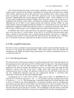
should try to avoid the potential slide risk area. A typical major landslide along a
highway in California is shown in Figure 14.10.
During the location of the Burma Road, due to insufficient time for detailed
survey, a section of road was located in a potential landslide area. After the road
FIGURE 14.10
Typical landslide along a highway cut area.
©2000 CRC Press LLC
was open to traffic, a massive slope failure took place. At one time, as many as six
slides in the cut slope occurred on the same day. Clearing the slides became a major
task. At last, the engineers gave up and – at great expense – relocated 10 miles of
the existing road to a stable area.
A granular soil that is looser than the critical density may pass into a state of
complete liquefaction if failure starts. Some of these failures may be referred to as
mud flow. Such a flow occurs rapidly and the mass that moves may continue to flow
to the lower ground a considerable distance away. Flow slides can take place in
slopes as flat as 5 to 10°, and may result in slides of great magnitude.
Almost every stiff clay is weakened by a network of hairline cracks or “slick-
ensides.” If the spacing of the joints is wide, the slope may remain stable even on
steep sloping ground during the dry season. However, if water is allowed to seep
into the cracks, the shearing resistance of the weakened clay may become too small
to counter the force of gravity and the slide occurs.
14.5 MAN-MADE SLOPES
Man-made slopes are necessary in the construction of highways, railroads, canals,
and other projects. In high ground, open cuts with adequate slopes will be necessary
and on low ground the stability of fill must be considered. Geotechnical engineers
seldom pay attention to the design of man-made open cuts and fill. They cover the
design with the standard construction specifications. For small projects with no
seepage problems, such procedures may be adequate. However, for larger projects,
such as locating a section of new highway, the designs of man-made slopes become
critical. The cost of an over-designed slope can exceed the cost of a long-span bridge.
At the same time, steep slopes can give maintenance crews years of headaches.
Experience has shown that slopes at 1 1/2 (horizontal) to 1 (vertical) are usually
stable. The sides of most railroad and highway cuts less than 20 ft use such slopes.
The standard slopes for water-carrying structures such as canals range between 2:1
and 3:1.
14.5.1 S
LOPES
IN
S
AND
Instead of failing on a circular surface, sand slopes fail by sliding parallel to the
slope. Sand located permanently above the water table is considered stable and cuts
can be made at standard angles. Slides occur only in loose saturated sands that
liquefy.
When the slope angle exceeds the angle of internal friction of sand, the sand
grains slide down the slope. The steepest slope that a sand can attain, therefore, is
equal to the angle of internal friction of the sand. The angle of repose of sand as it
forms a pile beneath a funnel from which it is poured is about the same as the angle
of internal friction of the sand in a loose condition. Geotechnical engineers seldom
have the opportunity to study the stability of a slope of sand, unless there is a sudden
rise of the water table or after an earthquake.
©2000 CRC Press LLC
14.5.2 S
LOPES
IN
C
LAY
The stability of a slope of clay can be expressed by Coulomb’s shearing strength
and shearing resistance relationship.
s = c +
s
tan
f
where s = shear strength, psf
c= cohesion, psf
s
= effective normal pressure, psf
f
= angle of internal friction
A chart of the stability number for different values of the slope angle
b
is shown
in Figure 14.11. For homogenous soft clay with
f
= 0, the stability number depends
only on the angle of the slope
b
and on the depth of the stratum.
If the value of
f
is greater than about 3°, the failure surface is always a toe
failure. The above figure can be used to determine the stability number for different
FIGURE 14.11
Chart for finding the stability of the slopes in homogenous unsaturated
clays and similar soils (after Liu).
©2000 CRC Press LLC
value, of
f
, by entering along the abscissa at the value of
b
and moving upward to
the line that indicates the
f
angle and then to the left, where the stability number is
read from the ordinate.
14.5.3 S
LOPES
OF
E
ARTH
D
AM
The design of a dam shell consists of the selection of the fill material on the basis
of its strength and availability for construction. Generally, the material is obtained
from borrow pits. Rock waste from a dam core excavation can also be used. For the
upstream side of the dam, consideration should be given to the seepage problem.
Thus, the degree of compaction of both soil and rock should be under control.
The slopes of most dams are established on the basis of experience and consid-
eration of the foundation conditions, availability and properties of material, height
of dam, and possibly other factors.
Typical upstream slopes range from 2.5(H) to 1(V) for gravel and sandy gravel
to 3.5(H) to 1(V) for sandy silts. Typical downstream slopes for the same soils are
2(H) to 1(V) to 3(H) to 1(V).
A seepage analysis is made on the trial design to determine the flow net and the
neutral stresses within the embankment and the foundation. Safety against seepage
erosion and the amount of leakage through the dam are computed.
Stability analyses are made of both faces of the dam, using the method of slices.
The upstream face is usually analyzed for the full reservoir, sudden drawdown, and
the empty reservoir before filling. The downstream face is analyzed for the full
reservoir and minimum tailwater and also for sudden drawdown of tailwater from
maximum to minimum if that condition can develop.
The construction of the Greyrock Dam embankment at Greyrock, Wyoming is
shown in Figure 14.12.
14.6 FACTOR OF SAFETY
The designs of cut and fill have been studied by many leading academicians. With
the use of the computer, all aspects of dam design can be accomplished accurately
and quickly. All studies involve some basic assumptions, as follows:
The soil is homogenous both in extent and in depth.
A single angle of internal friction and cohesion values can represent the entire
soil mass under investigation.
The assumed seepage condition will remain unaltered.
There will not be any external disturbance affecting the stability.
The type of affiliated structure has not been determined.
There will not be any unexpected surcharge load.
In order to cover the above uncertainties, geotechnical engineers assign various
values of “factor of safety” in an effort to cover the possibility of failures. Sower
listed in Table 14.1 the factor of safety applied to the most critical combination of
forces, loss of strength, and neutral stresses to which the structure will be subjected.
©2000 CRC Press LLC
Sower further stated that under ordinary conditions of loading, an earth dam
should have a minimum safety factor of 1.5. However, under extraordinary loading
conditions, such as designing a super flood followed by a sudden drawdown, a
minimum factor of safety of 1.2 to 1.25 is often considered adequate.
In addition to the uncertainty involved in the factor of safety, engineers must
consider “cost”; with an exception of dam design, if cost is not a factor, the risk of
a slope failure can be greatly reduced. The factor of safety values suggested by
Sower should be considered as design guides.
The factor of safety against sliding is determined by dividing the sum of forces
tending to resist sliding by the force tending to cause sliding. The slide-resisting
FIGURE 14.12
Embankment compaction, Greyrock Dam, Greyrock, Wyoming.
TABLE 14.1
Suggested Factor of Safety
Safety Factor Significance
Less than 1.0 Unsafe
1.0–1.2 Questionable safety
1.3–1.4 Satisfactory for cuts, fills; questionable for dams
1.5 or more Safe for dams
©2000 CRC Press LLC
forces are determined from laboratory testing on the so-called “representative sam-
ples.” As stated in Chapter 5, the shearing resistance determined from the direct
shear test or the triaxial shear test can be misleading. Consequently, the overall
shearing resistance against sliding for a slope, as computed in the laboratory, can
be very far from the realistic value. The term “factor of safety” as used by engineers
must be qualified.
Unfortunately, the term “factor of safety” as understood by lawyers is quite
different than that understood by engineers. When an engineer, in computation,
indicates that the factor of safety is 1.5, attorneys consider the figure absolute. If
upon further calculation the value is 1.4 instead of 1.5, a mistake is made, resulting
in damage. The designing engineer must pay for the error. At the same time, if upon
further calculation the value is 1.6, the engineer is clear and the responsibility for
the damage must rest on someone else. Such logic, unfortunately, is agreed upon
by judge and juries.
When dealing with soil, engineers should avoid the use of the term “factor of
safety.” Instead, the use of such language as, “We recommend …” should be encour-
aged. By so doing, many of the legal problems involving geotechnical reporting can
be minimized.
14.7 CASE EXAMPLES
14.7.1 H
OWELSON
H
ILL
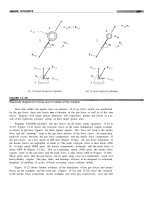
Howelson Hill is located to the south of Steamboat Springs, Colorado. It is the site
of international ski jumping competitions. In July 1976, a 41,000 cubic-yard land-
slide occurred during nearby excavation activity. The slide involved only surficial
colluvial deposits that overlie the Morrison Shale formation on the slope of the
north-south-trending bedrock.
The landslide area and all jump profiles were analyzed to determine the cause
of the landslide and the effects the slide had on the profile of the jump complex
design. A geological interpretation of all data was made. Stability analyses were
then conducted using effective strength parameters as determined from laboratory
tests. Circular and non-circular failure surfaces were considered in the stability
analysis. Typical stability analyses are shown in Figure 14.13.
Correlation of the geology and strength parameters was made to assess the
probability of similar slides in the adjacent jump area.
The following conclusions on the nature of the landslide were drawn, based on
the field investigation:
1. The slide was localized in the area of previous instability and the geologic
conditions were significantly different in the stable portions of the
mountainsides.
2. The primary mode of failure is transitional.
3. A buried bedrock topography controls the lateral extent of the landslide,
which is restricted to a narrow linear zone.
©2000 CRC Press LLC
4. Hot mineral springs were active at one time in the toe area of the landslide.
5. Older landslide movements have occurred in the area as indicated by the
claystone shale overlying the colluvium in some test pits. Surface evidence
of this older landslide is not present.
By the time the initial findings of the field investigation were determined, the
rate of the movement of the slide had slowed down to less than 1 in. per day. The
following remedial constructions were made:
1. A gravel trench drain was installed along the toe of the landslide.
2. A stabilizing berm of compacted soil was placed at the toe of the slide.
3. Open surface cracks in the slide mass were sealed by grading the slide
surface.
4. Surface drainage ditches were constructed at the crown of the slide and
at intervals along the slide.
5. To increase the factor of safety against sliding, retaining walls with foun-
dations on the bedrock were constructed at the site of the 90-meter, 70-meter
and 50-meter jumps.
After the completion of the remedial work, surface survey monuments were
established and have periodically been surveyed. No measurable movement has been
monitored.
14.7.2 C
HURCH
R
OCK
U
RANIUM
M
ILL
T
AILINGS
D
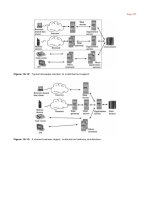
AM
The project site is located northwest of Gallup, New Mexico. The dam was to be
70 ft high and about 2 miles long. The purpose of the dam was to retain the waste
from uranium mining at Church Rock. The site is in Pipeline Valley, that consists
FIGURE 14.13
Non-circular analyses of final 70-meter profile.
©2000 CRC Press LLC
FIGURE 14.14
Howelson Hill sky jump slope failure.
©2000 CRC Press LLC
mainly of mancos shale and gullup sandstone, bounded to the north by Crevasses
Canyon formation and to the south by the Morrison formation. The valley floor is
topped with alluvium soil, its thickness varying from a few feet to more than 100 ft.
The design and stability analyses of the dam can be summarized as shown in
Figure 14.15. The construction of the dam was to be carried out in stages. The height
of the dam was to increase with the reservoir liquid level, until the maximum height
of 70 ft was reached. Construction of the starter dam took place in 1976. The height
of the dam reached about 30 ft when the accident took place.
Cracking of the dam embankment first appeared in June 1977 and was grouted.
Further large separation cracks appeared at the south end in 1978. The cracks
appeared to take place perpendicularly to the dam axis at the location where there
is an abrupt change in the depth of bedrock as well as the thickness of the alluvium.
Finally, in July 1979 the dam breached. All of the tailing liquid contained in the
reservoir escaped through the breach.
A board of inquiry, consisting of many of the top geotechnical engineers in the
country, was established to determine the cause of the failure. After months of
investigation, the experts carefully evaluated all possibilities. They listed the follow-
ing questionable items that may have caused the failure.
1. An excessively high free liquid surface, which came in contact with the
transverse crack in the starter dam
2. The use of cyclones to form the coarse sand bench
3. The recommended freeboard of 5 ft was not maintained
4. Action between the liquid acidic tailing and the soil in the embankments
5. The foundation soil problem
6. Inadequate stability analysis or insufficient compaction
7. A low factor of safety, perhaps below 1.0
8. Piping in the embankment
FIGURE 14.15
Church Rock Uranium Mill Tailings dam.
©2000 CRC Press LLC
9. Seepage through the embankment
10. Seismic effect
After careful evaluation, the general opinion was that the main cause of the
failure was differential settlement. Prior to construction, it was predicted that the
total settlement will be about 2.5 ft. Before breaching took place, the actual total
settlement reached about 5 ft. Due to the extreme variation of depth to bedrock along
the dam axis, differential settlement could be equal to total settlement.
Differential settlement resulted in embankment cracking. The introduction of
reservoir liquid through the cracks caused soil erosion and resulted in piping. Other
probable causes as listed above should not be ignored, but they are minor and are
not considered the major cause of the dam failure.
14.7.3 C
OLUMBIA
R
IVER
Numerous landslides have occurred along the banks of the Columbia River in the
vicinity of the Grand Coulee Dam, Washington. With the completion of the dam,
the water level of the river rose and greatly affected the stability of the natural bank
slope. The stability was further affected by the sudden drawdown of the reservoir.
Stability of the bank slope was under intensive study by the Bureau of Reclamation.
The study included the geology, the hydrology, and other related subjects. Publica-
tions of the studies are available in various technical journals.
In 1984, a staging area was developed immediately upstream from the Grand
Coulee Dam. Contractors were allowed to place fill on the bank within the designated
area. An accident occurred when a dump truck slid into the river, killing the operator.
The accident stirred up not only legal responsibility but also the issue of stability
of the existing slope along the banks of the Columbia River. Upon further intensive
studies, the following subjects were brought up for review:
On the natural slope:
The stability of the natural bank slope
The effect of the water level in the river on slope stability
The effect of the sudden drawdown
The consistency of the soil property
The criteria used in the stability analysis
The factor of safety of the natural slope
The history of the bank slide
The geology of the staging area
The ground water level
The significant of the bedrock elevation
The existing slope 1.3:1 (38°); is that a safe slope?
On the new fill:
The maximum permissible thickness
The soil property of the fill
The design slope of the fill
©2000 CRC Press LLC
FIGURE 14.16
Breaching of Church Rock Uranium Mill Tailings Dam.
©2000 CRC Press LLC
The criteria used for stability analysis of the fill slope
The method of the determination of the soil constant
The factor of safety of the fill slope
The frequency of the soil tests
The extent of the fill placement
The berm establishment
The after slide slope 1.5:1 (33°); is that a safe slope?
On the combined bank soil:
The combined design slope
The combined factor of safety
The geometry of the combined slope
The interaction of the fill and the natural soil
The slump failure; is that a possibility?
On the victim’s dumper:
The allowable weight of the dumper
The actual load carried by the dumper
The vibration of the dumper
The distance between the dumper and the edge of the berm
The above issues clearly indicated that the slope stability problem is much more
complicated than the textbook analysis. In fact, the issues involved are so compli-
cated that a rational solution cannot be readily found.
Finally, the case was narrowed down to the determination of the most desirable
factor of safety of the embankment slope. All other pertinent engineering issues such
as “effects of drawdown” were ignored. The case was settled out of the court. The
cause of the accident was never determined.
REFERENCES
C.M. Hsieh, Atlas of China, McGraw-Hill, 1973.
C. Liu and J.B. Evett, Soils and Foundations, Prentice-Hall, Englewood Cliffs, NJ, 1981.
J.D. Nelson and E.G. Thompson, Creep Failure of Slopes in Clay and Clay Shale, 12th Annual
Symposium for Soil Engineering and Engineering Geology, Boise, ID, 1974.
R. Peck, W. Hanson, and T.H. Thornburn, Foundation Engineering, John Wiley & Sons, 1974.
G.B. Sowers and G.S. Sowers, Introductory Soil Mechanics and Foundations, Collier-
Macmillan, London, 1970.
D.W. Taylor, Fundamentals of Soil Mechanics, John Wiley & Sons, New York, 1948.
K. Terzaghi, R. Peck, and G. Mesri, Soil Mechanics in Engineering Practice, John Wiley-
Interscience Publication, John Wiley & Sons, New York, 1996.
0-8493-????-?/97/$0.00+$.50
© 1997 by CRC Press LLC
15
©2000 CRC Press LLC
Distress Investigations
CONTENTS
15.1 Historical
15.1.1 Foundation Information
15.1.2 Movement Data
15.2 Investigation
15.2.1 Test Holes and Test Pits
15.3 Causes of Distress
15.3.1 Foundation Design
15.3.2 Construction
15.3.3 Maintenance
15.3.4 Earthquake
15.4 Structural Movement
15.4.1 Deflection
15.4.2 Thermal Movement
15.4.3 Prestressing
15.5 Distress of Major Structures
15.5.1 Drilled Pier Foundations
15.5.2 Watering Practice
15.5.3 Building Demolished
15.5.4 Debris Flow
References
In ancient times, structural damage was seldom a problem. Major structures were
founded on selected stable grounds with uniform subsoil. Building material consisted
mostly of timber capable of tolerating a great deal of movement without showing
damage. When damage appeared, it was taken for granted and “nothing to be alarmed
about.”
In the last century, with the advancement of building technology, architects put
steel, concrete, glass, and masonry into the same structure. Since each material has
a different thermal expansion index, it is not difficult to expect that they cannot
perform as a unit. Great architects such as Frank Lloyd Wright could not avoid
structural damage. Structural engineers took most of the blame until the emergence
of the foundation engineer. It was then – in the eyes of many – that every problem
became related to foundation movement. Geotechnical engineers were helpless in
trying to defend their designs.
Our society demands perfect performance from the building industry. It wants
to pay the least yet it expects the most from investments. The legal profession is on
the side of the consumers. The insurance business cannot afford to lose money so
©2000 CRC Press LLC
the premiums skyrocket. Thus, a unique triangle has been established between the
design profession, the legal partners, and the insurance business. The easiest culprits
to blame are, of course, the design professionals.
When distress takes place, the owner wants to know the cause of the damage in
order to establish the party responsible for the damage.
15.1 HISTORICAL
The first step toward an investigation of a distressed structure is to obtain its complete
history. Unfortunately, such information is often lacking and it is necessary to
uncover much of the required information by exploration.
15.1.1 F
OUNDATION
I
NFORMATION
Efforts should be made to obtain information about the existing foundation. For
buildings erected before 1960, such information is generally sketchy. Soil tests on
individual sites have become a requirement since 1960. From the soil test data, it is
possible to determine the following:
1. Type of foundation
2. Design criteria
3. Water table condition
4. Type of foundation soil
5. Moisture content of foundation soils
6. Settlement or swelling potential of foundation soils
Sometimes the subsoil investigation is not conducted for the specific building
but for the general area. In such cases, the subsoil information has only limited use.
Care should be taken to locate the nearest test hole to the structure under investiga-
tion, so that it is possible to determine as closely as possible the subsoil conditions
beneath the distressed building.
The above information can be invaluable in finding the cause of movement.The
second step is to check the foundation plan. Again, such information may not be
available, either because the drawing is lost or the concerned party does not want
to produce it. The foundation plan can reveal if the recommendations given in the
soil report have been followed. These are:
1. The total load and the dead load exerted on the footings or piers
2. The size of footings or piers
3. The length of piers or piles
4. Pier reinforcement, pier connection, pier spacing, and others
5. Expansion joints, dowel bars, underslab gravel, slab reinforcement, and
other details
6. Subdrain system
7. Backfill and lateral pressure
©2000 CRC Press LLC
If the above information is available, the investigation can be greatly simplified.
This is analogous to the case in which the complete medical record of a patient is
at the disposal of the examining doctor. It is also necessary to examine the qualifi-
cations of the designer, including whether the design was made by a registered
professional engineer or by a contractor.
When the above information is not available, it is necessary to expose the
foundation system by excavation. In the case of a non-basement building, excavation
can be easily performed outside the building immediately adjacent to the grade
beam. In the case of a basement structure, it is necessary to break the concrete slab
inside the basement in order to reach the foundation system.
For a deep foundation system, it is difficult to expose the entire length of the
pier in order to determine the settlement or uplifting of the pier. An experienced
engineer can sometimes gain a great deal of information from the examination of
the upper portion of the pier.
Undersized footings can cause settlement problems. Oversized footings are the
common cause of uplift in expansive soils. Misplaced footings can cause cracks
induced from lateral pressure. Above all, if water is found seeping into the foundation
system, it can be the source of all evils.
Logs kept by the driller are sometimes available. In such cases, a complete
picture of the pier system will be helpful. This can also provide information on the
depth of penetration of the piers into the bedrock. In case of a pile system, the
penetration resistance and the blows of the pile hammer can be the key to the entire
problem.
15.1.2 M
OVEMENT
D
ATA
Efforts should be made to obtain the chronological data on the building’s movement.
Items such as the date the building was completed, the date the first owner moved
in, and the date the first crack appeared should be noted in detail. All information
obtained from the owner should be carefully scrutinized for its validity. If the owner
intends to sue the builder to recover damages, the information may be exaggerated.
With careful interrogation and keen observation, the true story can sometimes be
revealed.
Since almost all foundation movement problems are associated with water, it is
imperative that the investigation of the sources of water that entered the structure
be the first order of the distress investigation. On the exterior of the building, it is
helpful to find out the lawn watering practice, the setting of the automatic sprinkling
system, and the condition of the backfill. Most owners deny the occurrence of
excessive irrigation of the lawn and flower beds. They certainly will not tell you
about the time they left the hose running for the entire weekend.
In the interior of the building, the primary information can be obtained in the
basement area. Watermarks on the walls usually tell the story of seepage. A complete
record on seepage water should be obtained, noting the first appearance of water in
the basement, the location of seepage, the amount of observed water, and whether
seepage has taken place after heavy precipitation.
©2000 CRC Press LLC
Also important is the performance of the utility lines. Was plumbing difficulty
experienced in past years? Had the floor drain been plugged? A recent investigation
revealed that a house’s sewer line was never connected to the main sewer line, and
raw sewage accumulated around the house for as long as 15 years. It is fortunate
that the house is still standing. In another case, the basement shower drain was not
connected to the sewer line. For years, the error was not detected until the engineer
entered the crawl space and found the excessive wetting condition. The obvious
seepage problem is shown in Figure 15.1.
It is also important to know whether during construction there were any unusual
incidents that contributed to the building’s distress at a later date. If such information
is available from an observant owner, it can unlock many movement puzzles. There
are instances in which the soil was flooded during construction, and movement took
place even before the building was completed. One case reported a partially com-
pleted house whose basement was covered with more than 2 ft of snow that the
contractor failed to remove before enclosing the structure.
In the course of information gathering, all hearsay should be screened. Stories such
as an underground river running under the structure, a building sliding downhill, and
the bentonite in the soil pulling the building apart should not be believed. An experienced
engineer will dismiss most of such hearsay and focus on concrete evidence.
15.2 INVESTIGATION
The cause of cracking of a distressed structure can usually be determined from visual
examination by an experienced geotechnical engineer. However, at times it will be
necessary to perform testing of the soil samples, either to obtain pertinent information
or to confirm a preconceived opinion.
Owners sometimes feel cheated if the engineers did not perform drilling and
sampling. They feel that by so doing, the cause of the problem can be revealed, not
knowing that sampling the subsoil outside the structure can yield little information
on the cause of distress. Most academicians prefer to have test data before them to
support their findings. They may order drilling as the first step of the investigation.
15.2.1 T
EST
H
OLES
AND
T
EST
P
ITS
Test holes should be drilled adjacent to the building, and sufficient samples should
be taken for the determination of the consolidation or swelling characteristics and
the moisture content of the soils. At least one test hole should be drilled away from
the structure in an area unaffected by building construction. The physical character-
istics of the soil obtained from the adjacent and remote test holes can be compared.
For a distressed structure, the soils immediately adjacent to the foundation
generally have been wetted excessively. Laboratory testing on samples taken gen-
erally shows a low settlement or swelling tendency. Initial characteristics of the
foundation soils can be revealed by air-drying the sample to the natural moisture
content and then by subjecting it to wetting. Samples obtained from areas unaffected
by building construction should give information relative to the soil behavior at the
time of construction.
©2000 CRC Press LLC
FIGURE 15.1
Water seeped into the lower floor.
©2000 CRC Press LLC
The most positive method of determining the subsoil condition and construction
details in the foundation system is by opening test pits. Test pits should be excavated
adjacent to the grade beam and next to the interior supports. By investigating the
subsoil in the test pit, the following can be revealed:
1. The foundation system
2. The moisture content of the soil; samples should be taken every 12 in. to
a depth of at least 5 ft
3. The connection between the piers or piles with the grade beam
4. The presence of tension cracks on the pier shaft
5. The presence of underslab gravel, and the condition of the underslab soils
Distress investigation can be greatly simplified when crawl space construction
is used in the system. By entering the crawl space, the engineer is able not only to
inspect the foundation system but also to examine the drainage system, ventilation,
pipe connections, surface soil moisture condition, and other details that the owner
has ignored.
15.3 CAUSES OF DISTRESS
Most distressed structures that require investigation and remedial construction
belong to a relatively low-cost category; the owner put in a great deal of money and
expected a good return for the investment. The degree of the distress that appears
in a structure varies greatly. Some of the distress is so severe that a complete
demolition of the structure will be required. Others appear as hairline cracks which
can be easily repaired. Some owners insist on complete and prompt repair and do
not hesitate to take the matter to the court. After reviewing the design, the construc-
tion, and the maintenance practice, the foundation engineer should be able to provide
a logical answer to the problem.
15.3.1 F
OUNDATION
D
ESIGN
Every state in the union now requires a foundation design with a professional
engineer’s seal. However, a soil report is not required for the foundation design.
Some engineers are not familiar with the local conditions and adhere to traditional
practices. An engineer not familiar with the swelling soils problems who designs
the footings with settlement considerations can encounter serious problems. In
selecting a foundation engineer, experience should be the first consideration.
Despite any deficiencies of a drilled pier or a footing construction, a properly
engineered foundation system seldom suffers major distress even under the most
adverse conditions. Some buildings that suffer severe damages are designed and
constructed by contractors without the benefit of a soil or structural engineer.
Some contractors take the matter entirely into their own hands and prewet the
foundation soil, puddle the backfill, reinforce the footings instead of the foundation
walls, drill oversized piers, and expect a stable building. These buildings may remain
©2000 CRC Press LLC
in good condition for years and may provide an excuse to the builder to continue
this undesirable practice.
15.3.2 C
ONSTRUCTION
Legally, if the contractor follows every detail specified in the specifications and
design provided by the engineers, his liability in the event of future structure damage
can be cleared. Still, the contractor cannot avoid being named in a lawsuit. In court
every effort is usually made to prove the contractor’s negligence. For instance, the
absence of slab reinforcement as specified should not be important with respect to
slab cracking; however, in court, this can appear as a glaring mistake on the part of
the contractor for not following the design.
There are cases in which the contractor abuses every rule of good construction
practice and expects the infractions to go undetected. Faulty construction will not
be uncovered until thorough inspections are made. Figure 15.2 shows the mislocation
of piers.
15.3.3 M
AINTENANCE
Poor or neglected maintenance can be the cause of building distress. The most
common poor maintenance practices are as follows:
1. Water ponding adjacent to the building
2. Flower beds located adjacent to the foundation walls
3. Tree roots extended under the building
4. Absence of outlet of the exterior drain
FIGURE 15.2
Timber supports used to correct the missed piers.
©2000 CRC Press LLC
5. No outlet for the roof downspout
6. Flooded crawl space
7. Poor remodeling construction
Some owners purposefully aggravate the damage by heavy watering for the
purpose of impressing the judge and jury in order to obtain better compensation.
If a civil action is instigated resulting from a foundation problem, the strongest
defense the contractor possesses against the owner’s suit is that the owner did not
provide proper drainage around the building. An alert developer issues each home
owner a manual on the care of drainage around the house. In the event of a complaint,
the builder can then have recourse back to the owner.
15.3.4 E
ARTHQUAKE
Potential seismic activity is a major concern in structural design in many regions of
the world. Earthquake potential must be considered in the design of major structures
such as dams and high-rise buildings. Earthquakes can result in the direct tearing
of structures that lie on a fault.
Whenever there is a light tremor, it gives a good excuse for all parties concerned
to say that the cracking of the structure is an act of God. Indeed, it is difficult if not
impossible to differentiate cracks resulting from earth tremor and cracks resulting
from foundation movement.
One method of determination is to examine the mortar between the cracks. If
the crack is due to an earthquake, the mortar is ground up into fine powder, while
in the case of foundation movement, the mortar will remain in pieces.
15.4 STRUCTURAL MOVEMENT
It is easy to blame all building distress on foundation movement. Unfortunately, it
is difficult to differentiate distress caused by foundation movement and distress
caused from structural movement. In the Rocky Mountain area, most of the general
public is fully aware of the swelling soil problem and believes that all problems are
generated from swelling soils. Most structural engineers are aware that some move-
ment can be caused from structural design, but hesitate to point it out. Why ask for
trouble?
Structural movement problems are explained well in Richard Weingardt’s paper
“All Structures Move.” He stated: “The structures are like people, they breathe.” The
following is part of Weingardt’s analysis.
15.4.1 D
EFLECTION
The normal allowable deflection, by most codes, is 1/360. This translates into about
a 5/8 in. deflection in a 20-ft span. Deflections of this magnitude are not uncommon.
Excessive deflections may result in curvatures or misalignments perceptible to the
eye. Lesser deflections may result in fractures of elements, such as plaster or
masonry.
©2000 CRC Press LLC
Deflection of load-carrying members may result in the transfer of loads to non-
structural elements, such as window frames or interior partitions. This situation must
often be handled by detailing connections that allow for a limited movement. This
requires close coordination of the architect and the structural engineer.
15.4.2 T
HERMAL
M
OVEMENT
Exterior elements and surfaces of buildings are subjected to a range of temperatures
which in northern climates can be as much as 140°F. The resulting expansion and
contraction can cause cracks similiar to cracks from foundation movement, as shown
in Figure 15.3.
There is movement of the entire building structure. Since the substructure is
kept at a relatively constant temperature by the ground, there is a buildup of differ-
ential length between the lower and upper portions of the building, which can cause
critical conditions of shear in end-walls or sideways deflection of end columns.
Where separate wings of the building are joined, as in L- or H-shaped plans, one
wing may pull away or push against the other. The solution to this problem is usually
to provide expansion joints.
FIGURE 15.3
Cracks due to temperature in massive brick construction.
©2000 CRC Press LLC
Different materials have different thermal properties. When exposed to temper-
ature changes, they should not be rigidly connected to one another. Steel beams or
columns encased in masonry should be provided with a void or slip jointed ends.
Another recommended standard detailing practice is to weld alternate ends of
steel joists or prestressed members, so they are allowed minor movement without
tearing themselves apart.
15.4.3 P
RESTRESSING
The creep of prestressed concrete members such as twin-tee floors and roofs can
continue for many years. Figure 15.4 indicates a severe crack that developed in a
twin-tee structural slab. The building is founded with drilled piers, and the exterior
walls are in excellent condition. These cracks had nothing to do with the foundation
movement.
It is easy to jump to the conclusion that the foundation system has moved and
is responsible for the structural damage. It is sometimes impossible to prove that
the damage is actually related to structural movement in the other component parts
of the structure.
Weingardt, in the conclusion of his paper, stated: “The awareness that structures
move, in itself, is the first step in designing buildings, to eliminate cracking. There
is not one simple solution for an expansion joint or control joint that will work for
all materials. Masonry walls are different from concrete walls. Concrete slabs are
different than steel beams.”
FIGURE 15.4
Floor crack due to creep of twin-tee concrete slab.
©2000 CRC Press LLC
15.5 DISTRESS OF MAJOR STRUCTURES
When the distress or failure of a major structure takes place, it may result in litigation.
The sequence of events usually starts with the owner concerned about the integrity
of the structure. Owners blame faulty construction. The contractors blame everyone
concerned except themselves. The owners turn to academicians for expert opinions.
The professors, who usually have little experience in dealing with foundation move-
ment, use various theories, such as plastic flow, wave propagation, diffusion, etc.,
to explain the causes of movement. None can confirm or dispute their theories. It
is of course easy to discuss the design after distress has taken place. Bear in mind,
when the geotechnical engineers take on the assignment to recommend the design
of the foundation system, they are not paid to write a thesis on the project.
It takes months and sometimes years to complete the depositions in a lawsuit.
Expert witnesses may include professors, builders, surveyors, architects, or insurance
agents; the experienced geotechnical engineers are seldom involved. Ninety percent
of the cases are settled out of court. The defendants would rather forget the entire
matter, than spend additional money to fight it in court. For the limited cases that are
tried in court, the issues are usually badly distorted. The attorneys tend to present some
unimportant events and elaborate on them. The juries are at a complete loss listening
to the theoretical approaches advanced by the academicians. The truth of the matter
is seldom if ever revealed. The winners of the entire episode are the attorneys.
15.5.1 D
RILLED
P
IER
F
OUNDATIONS
Drilled piers are used for most of the major structures in the western U.S. Distress
of structures caused by improper design of the pier system is seldom reported.
One example cites that during the construction of a warehouse building, several
piers had settled more than 3 in. The tilt-up panels were jacked up and shimmed,
but settlement continued. After intensive study, it was concluded that the problem
resulted from the improper placement of pier concrete. A stress wave propagation
testing method was introduced to determine the condition of the distressed piers.
Stress wave propagation testing consists of inducing a shock wave at the top of
a pier and measuring the compression wave propagation and attenuation character-
istics with an oscilloscope that is connected to a receiver mounted on the top of the
distressed pier. Test results can be used to identify voids in concrete, voids at the
base of a pier, and disturbed conditions along the piers.
Test results indicated the piers that suffered excessive settlement exhibited higher
reflection numbers, thus indicating the presence of relatively softer materials sur-
rounding the piers.
Stress wave propagation tests were followed by load tests. The selection of the
piers for load tests was based on the results of wave propagation tests. The piers
were loaded to approximately 60 kips by means of a 50-ton jack reacting against a
crane. The results of the load tests are shown in Figure 15.5.
©2000 CRC Press LLC
Tests indicate that piers 16-C and 14-C were both deformed more than generally
acceptable at the applied load. It was then decided to excavate adjacent to the
distressed piers to evaluate the soil and rock conditions along the sides and beneath
the piers. Excavation revealed that a significant portion of the zone adjacent to the
sides of the piers contained disturbed materials. The material was about 1 in. thick
and had a high moisture content relative to the natural on-site materials.
It was concluded that the cause of the excessive settlement was from the pier’s
installation procedure. It was possible that the caisson rig used did not have the
auger properly attached to the kelly bar with the axis of the coincident with the axis
of the kelly bar. It was also possible that the auger was either loosely attached to
the kelly bar allowing it to wobble, or there was a bend in the auger or the kelly bar.
The defective piers were replaced and construction continued with no further
problems. Since the pier drilling operation was inspected by the geotechnical con-
sultant, the cost of the investigation and remedial construction was shared by the
consultant and the contractor. Mishaps similar to this case can hardly be avoided
even with careful inspection.
FIGURE 15.5
Load test results.
©2000 CRC Press LLC
15.5.2 W
ATERING
P
RACTICE
A nursing home complex with a drilled pier foundation is located in a swelling soil
area in Colorado. About 2 years after the completion of the buildings, the floor slab
in a part of the building heaved. Floor movement resulted in the cracking of the
slab-bearing partition walls and the distortion of the ceiling structure. An open
courtyard was located at the central portion of the building complex. The courtyard
was covered with a lawn and flower beds and was heavily irrigated. The design team
advised the administration to regulate its watering practice but was ignored.
The case was brought to court. After 2 years of intense litigation, the adminis-
tration finally obtained an expert from an eastern university who had no experience
in expansive soil. After examining the distressed photographs, the expert recom-
mended the demolition of all buildings.
Geotechnical engineers finally convinced the owner to convert the lawn-covered
court to a concrete playground and regulate the watering practice around the build-
ings. The building’s movement was arrested and the necessary repairs made. Today,
the buildings are in such good condition that the owner decided to build additions
using the original design criteria.
The cost of this litigation far exceeded the total cost of the buildings. The case
illustrates the danger of selecting the wrong expert in our legal system. It is a shame
that some of our professionals are willing to become advocation for an attorney.
15.5.3 B
UILDING
D
EMOLISHED
An unfortunate case of distress investigation took place in Manoa, Hawaii. A 5-story
concrete and masonry structure was demolished only a few years after completion.
Both the foundation system and structural analysis of the building were made by
leading nationally renowned consulting engineering firms. The distressed structure
was a part of the building complex that varied from two to six stories in height and
was connected by corridors at the upper level. The outstanding features of the initial
investigation are as follows:
1. A soil report was made for the entire building complex. No test hole was
made at the site of the distressed building.
2. The upper soils consist of stiff, highly plastic silty clays with varying
amounts of decomposed basalt gravel.
3. A spread footing foundation placed on the upper soils designed for a
bearing pressure of 5000 psf was recommended.
4. It is likely that fill was placed on the site. No control of fill placement
was made.
The cracking experienced at the building was essentially in the horizontal pattern
and major cracking took place at the header beam with the column. Vertical cracks
occurred in the brick course, but only a few with a diagonal pattern.
The cause of cracking was investigated by fewer than a dozen experts in
geotechnical as well as structural engineering. Since some tests indicated that the