Soils and Foundations Handbook phần 9 pdf
Bạn đang xem bản rút gọn của tài liệu. Xem và tải ngay bản đầy đủ của tài liệu tại đây (664.16 KB, 18 trang )
130
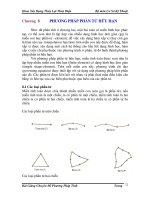
Figure 36, Schematic of Pile Driving Analyzer and Data Recording System (After
PDI, 1996)
131
Figure 37, Pile Driving Analyzer, Model PAK (After PDI, 1993)
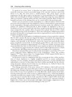
Figure 38, Static Load Test
132
Figure 39, Axial Statnamic Load Test
Figure 40, Lateral Statnamic Load Test
133
Figure 41, Osterberg Load Cells
Figure 42, Pile Integrity Tester (After PDI, 1993)
134
Figure 43, Shaft Inspection Device
135
10.10 References
1. Butler, H.D. and Hoy, Horace E.; The Texas Quick-Load Method for
Foundation Load Testing - Users Manual, FHWA-IP-77-8, 1976.
2. Goble, G.G. & Rausche, Frank, GRLWEAP, Wave Equation Analysis of Pile
Foundations, GRL & Associates, Inc., 1991.
3. Shih-Tower and Reese, Lymon C.; Com624P – Laterally Loaded Pile
Analysis Program for the Microcomputer Version 2.0, FHWA-SA-91-048.
4. Kyfor, Zenon G., Schmore, Austars R., Carlo, Thomas A., and Baily, Paul F.;
Static Testing of Deep Foundations, FHWA-SA-91-042, 1992.
5. Dunnicliff, John, Geotechnical Instrumentation for Monitoring Field
Performance, NCHRP Synthesis 89, Transportation Research Board, 1993.
6. Osterberg, J.O.; The Osterberg CELL for Load Testing Drilled Shafts and
Driven Piles, FHWA-SA-94-035, 1995.
7. Hannigan, P.J., Goble, G.G., Thendean, G., Likins, G.E., and Rausche, F.,
Manual on Design and Construction of Driven Pile Foundations, FHWA-HI-
97-013 and 14, 1996.
8. Pile Driving Analyzer Manual, PAK, Pile Dynamics, Inc., Cleveland, Ohio,
1997.
9. Paikowsky, Samuel G. and Tolosko, Terry A.; Extrapolation of Pile Capacity
From Non-Failed Load Tests, FHWA-RD-99-170, 1999.
10. Dunnicliff, John, Geotechnical Instrumentation, FHWA-HI-98-034, 1998.
10.11 Specifications and Standards
Subject ASTM AASHTO FM
- - -
- - -
Viscosity of Slurry - - 8-RP13B-2
PH of Slurry - - 8-RP13B-4
Standard Test Method for Piles Under Static
Axial Compressive Load
D 1143 - -
Standard Test Method for Individual Piles Under
Static Axial Tensile Load
D 3689 - -
Standard Test Method for Piles Under Lateral
Loads
D 3966 - -
Standard Test Method for Density of Bentonitic
Slurries
D 4380 - 8-RP13B-1
Standard Test Method for Sand Content by
Volume of Bentonitic Slurries
D 4381 - 8-RP13B-3
Standard Test Method for High-Strain Dynamic
Testing of Piles
D 4945 T 298 -
136
Subject ASTM AASHTO FM
Standard Practices for Preserving and
Transporting Rock Core Samples
D 5079 - -
Standard Test Method for Low Strain Integrity
Testing of Piles
D 5882 - -
137
Chapter 11
11 Design-Build Projects
Typically more geotechnical investigation is performed for Design-build projects
than for normal design-bid-construct projects. This occurs because a preliminary
investigation is performed by the Department during the planning and development
phase, and then during the design and construction phase, the Design-build team
performs the design specific investigation. The total may exceed 120% of a normal
investigation. The Design-build team shall be responsible for its own analysis of any and
all data used by the team.
11.1 Planning and Development Phase:
11.1.1 Department’s Geotechnical Engineer Responsibilities
The Department’s geotechnical engineer gathers data on the conditions at the site
sufficient for the design-build team to make a realistic proposal. It is preferred to
perform as complete a geotechnical field and laboratory investigation as time
permits, and provide the data to the Design-build teams for their use in preparing
preliminary designs and technical proposals. Upon completion of the preliminary
subsurface investigation, the information obtained must be compiled in a format,
which will present the data collected to the various design-build teams. The
limited geotechnical data collected prior to bidding is provided to prospective
teams for information only. Preliminary geotechnical reports prepared by the
Department for use by Design-Build Teams should not include analysis of the
geotechnical information or any suggestions for handling any potential problems.
11.1.2 Design-build Team Responsibilities
Design-Build Teams are not yet selected at this time. Potential teams submit
letters of interests from which a short list is determined.
11.2 Technical Proposals & Bidding Phase
11.2.1 Department’s Geotechnical Engineer Responsibilities
The Department’s geotechnical engineer answers questions from the design-build
team through the project manager, reviews technical proposals and provides
recommendations to other technical reviewers regarding the completeness and
appropriateness of proposed supplemental field testing and load testing programs.
11.2.2 Design-Build Team Responsibilities
Short listed Design-Build Teams perform analyses of the preliminary
geotechnical data and any additional data they gather independently. The teams
138
determine the appropriate design and construction methods based on their
approach/equipment; submit technical proposals and bids.
11.3 Design/Construction Phase
11.3.1 Department’s Geotechnical Engineer
The Department’s geotechnical engineer reviews design and construction methods
for compliance with the contract documents and performs verification testing as
required.
11.3.2 Design-Build Team
The design-build team meets the requirements set forth in the contract documents.
The team shall:
a) Gather additional geotechnical data and testing (such as borings, field tests,
laboratory tests, load tests, etc.) as required.
b) Complete the design process.
c) Prepare geotechnical reports including, as a minimum:
1. Geotechnical report for roadway soil survey:
a. Description of significant geologic and topographic features of the site.
b. Description of width, composition, and condition of existing roadway.
c. Description of specialized methods used during subsurface
exploration, in-situ testing, and laboratory testing; along with the raw
data from these tests.
d. Soil conservation services (SCS/USDA) and USGS maps, depicting
the project location.
e. Boring location plan, plots of boring logs and/or cone soundings
f. Results of roadway soil survey borings performed.
g. Any other pertinent information.
h. Analysis of the geotechnical information.
i. Recommendations on handling problem conditions observed in the
borings.
2. Geotechnical report for structures:
a. Vicinity map, potentiometric map, USGS and soil survey maps
(SCS/USDA), depicting the project location.
b. Description of the methods used in the field investigation, including
the types and frequencies of all in-situ tests.
c. Description of the laboratory-testing phase, including any special test
methods employed.
139
d. Boring location plan and plots of boring logs and/or cone soundings.
Note the size of rock core sampled. For exploratory borings, rock
cores shall produce 2.4 inch (61 mm) minimum diameter samples
(although 4 inch {101.6 mm} diameter rock cores are preferable). For
pilot holes, performed in drilled shaft locations, rock cores shall
produce 4 inch (101.6 mm) minimum diameter samples. Figures 33
and Figure 34 present examples of Report of Core Borings and Report
of Cone Soundings sheets. Include these sheets in the final plans. Plot
the borings using the standard soil type symbols shown in Figure 35
.
e. Environmental classification for both substructure and superstructure,
based on results of corrosivity tests. This information is also reported
on the Report of Core Borings sheet. For extremely aggressive
classification, note which parameter(s) requires the category.
f. Any other pertinent information.
g. Analysis of the geotechnical information.
h. Anticipated procedures for handling problem conditions observed in
the borings.
d) Construct the project.
e) Certify the foundation capacity and integrity prior to the Department’s
verification testing.
140
Appendix A
Determination of Design Skin Friction for Drilled Shafts
Socketed in the Florida Limestone
(Reprint of 1998 Design Conference Presentation by Peter Lai)
141
Introduction
The highly variable strength properties of the Florida limestone formation always
prompted the question of what design skin friction should be used for a drilled shaft
socketed in it. Some engineers even decide that doing any tests on rock cores obtained
from the project site is senseless because of the uncertainties associated with a spatial
variability of the limestone. This presentation provides a method that may be helpful for
determining a reasonable design skin friction value from a number of laboratory
unconfined compression and split tensile tests.
Design Method
On the basis of the study done by the University of Florida, the following method
proposed by Prof. McVay seems to be the most appropriate for the Florida limestone. The
ultimate skin friction for the portion socketed in the rock is expressed as
where : f
su
is the ultimate side friction,
q
u
is the unconfined compression strength of rock core, and
q
t
is the split tensile strength (McVay, 1992).
To consider the spatial variations of the rock qualities, the average REC (%
recovery in decimal) is applied to the ultimate unit side friction, f
su
, and the product is
used as the design ultimate side friction.
The Department engineers have used this method for several years now and it has
provided fairly good design skin friction as compared with load test data. However, there
are some uncertainties of how to obtain the q
u
, q
t
, and REC.
Rock Sampling and Laboratory Testing
The main thing that makes the design method work is the quality of the rock
cores. The rock core sample quality is hinged on the sampling techniques as well as the
size and type of the core barrel used. The porous nature of the Florida limestone makes
the larger diameter sampler more favorable than the smaller diameter sampler. Therefore,
in the FDOT’s “Soils and Foundation Handbook”, a minimum core barrel size of 61 mm
(2.4”) I.D. is required and a 101.6 mm (6”) I.D. core barrel is recommended for better
evaluation of the Florida limestone properties. Furthermore, the handbook also
recommends using a double barrel as a minimum to have better percentage recovery as
well as RQD. After obtaining the better quality core samples, the engineer can select
more representative specimens for laboratory unconfined compression and split tensile
tests. Thus better shear strength test data can be obtained for more an accurate design skin
friction.
Data Reduction Method
The data reduction method presented here is intent to provide a means to obtain a
f
REC =
)
f
(
SU
SU
DESIGN
q
q
2
1
=
f
tusu
142
more reliable q
u
, q
t
, and REC values that can provide realistic design skin friction for the
rock formation yet be conservative. This method involves the following steps of analyses.
1. Find the mean values and standard deviations of both the q
u
, and q
t
strength tests.
2. Establish the upper and lower bounds of each type of strength tests by using the
mean values, +/- the standard deviations.
3. Discount all the data that are larger or smaller than the established upper and
lower bounds, respectively.
4. Recalculate the mean values of each strength test using the data set that fall within
the boundaries.
5. Establish the upper and lower bounds of q
u
, and q
t
.
6. Use the q
u
, and q
t
obtained from steps 4 and 5 to calculate the ultimate skin
friction, f
su
.
7. Multiply the ultimate skin friction f
su
by the mean REC (in decimal) to account
for the spatial variability.
8. The allowable or design skin friction can then be obtained by applying an
appropriated factor of safety or load factor.
An example data set is provided for demonstration (see Table A-1).
143
Table A- 1
Core Sample Elevations
Boring No.
Top
Bottom
% REC
q
u,
ksf
q
t
, ksf
B-1
-62.24
-65.42
30
64.4
B-1
-72.42
-75.42
67
194.3
54.7
B-1
-82.42
-87.42
13
228.4
B-2
-36.58
-41.58
18
338.2
B-9
-74.42
-82.42
5
53
B-9
-89.42
-94.4
43
49.3
B-9
-89.4
-94.4
43
65.8
S-12
-30
-35
60
422.4
136.7
S-12
-35
-40
48
234
38.7
S-12
-50
-55
48
39.2
B-7
-44.4
-52.4
18
87
B-7
-92.9
-97.4
98
52.6
B-7
-97.4
-102.4
66
235
B-7
-134.4
-142.4
35
281.2
129.3
B-11
-34.2
-39.2
38
288
B-11
-34.2
-39.2
38
758.9
378.1
B-11
-34.2
-39.2
38
225.2
B-11
-76.4
-81.4
33
52.6
B-11
-90.4
-95.4
60
137.4
N-14
-40
-43
63
778.7
B-10
-33.4
-41.4
46
566.9
297.6
B-10
-33.4
-41.4
46
105.3
B-10
-46.4
-51.4
69
888.8
99.7
B-10
-46.4
-54.4
69
425.8
121
B-10
-46.4
-51.4
69
131.5
B-8
-48.9
-57.9
48
317.4
110.9
B-8
-48.9
-57.9
48
545.5
108
B-8
-48.9
-57.9
48
153.6
B-8
-59.9
-67.9
50
570.2
80.8
B-8
-99.9
-107.9
17
28.1
N-17
-58.1
-63
33
864.0
90.5
S-15
-48.5
-53.5
55
102.8
S-15
-48.5
-53.5
55
34.9
S-15
-65
-70
61
76.7
15.3
B-6
-64.1
-72.1
51
116.4
24.8
B-6
-74
-82
57
730.7
202.8
B-6
-114
-122
45
41.9
N-25
-58.8
-63.3
85
53.1
N-25
-68.8
-73.3
80
562.5
N-25
-73.3
-78.3
47
662.9
SUM
1941
9491.4
3962.1
MEAN
48.5
451.9
116.5
STANDARD DEVIATION
268.5
88.5
UPPER BOUND
720.4
205.1
LOWER BOUND
183.4
27.9
144
Table A- 2
Core Sample Elevations
Boring No.
Top Bottom
% REC
q
u,
ksf
q
t
, ksf
B-1
-62.24
-65.42
30
64.4
B-1
-72.42
-75.42
67
194.3
54.7
B-1
-82.42
-87.42
13
228.4
B-2
-36.58
-41.58
18
338.2
B-9
-74.42
-82.42
5
53
B-9
-89.42
-94.4
43
49.3
B-9
-89.4
-94.4
43
65.8
S-12
-30
-35
60
422.4
136.7
S-12
-35
-40
48
234
38.7
S-12
-50
-55
48
39.2
B-7
-44.4
-52.4
18
87
B-7
-92.9
-97.4
98
52.6
B-7
-97.4
-102.4
66
235
B-7
-134.4
-142.4
35
281.2
129.3
B-11
-34.2
-39.2
38
288
B-11
-34.2
-39.2
38
758.9
378.1
B-11
-34.2
-39.2
38
225.2
B-11
-76.4
-81.4
33
52.6
B-11
-90.4
-95.4
60
137.4
N-14
-40
-43
63
778.7
B-10
-33.4
-41.4
46
566.9
297.6
B-10
-33.4
-41.4
46
105.3
B-10
-46.4
-51.4
69
888.8
99.7
B-10
-46.4
-54.4
69
425.8
121
B-10
-46.4
-51.4
69
131.5
B-8
-48.9
-57.9
48
317.4
110.9
B-8
-48.9
-57.9
48
545.5
108
B-8
-48.9
-57.9
48
153.6
B-8
-59.9
-67.9
50
570.2
80.8
B-8
-99.9
-107.9
17
28.1
N-17
-58.1
-63
33
864.0
90.5
S-15
-48.5
-53.5
55
102.8
S-15
-48.5
-53.5
55
34.9
S-15
-65
-70
61
76.7
15.3
B-6
-64.1
-72.1
51
116.4
24.8
B-6
-74
-82
57
730.7
202.8
B-6
-114
-122
45
41.9
N-25
-58.8
-63.3
85
53.1
N-25
-68.8
-73.3
80
562.5
N-25
-73.3
-78.3
47
662.9
SUM
1941
5121.3
1800.9
MEAN
48.5
426.7
78.3
STANDARD DEVIATION
147.3
35.9
UPPER BOUND
574.1
114.2
LOWER BOUND
279.3
42.3
145
Use the upper and lower bounds of q
u
and q
t
as guides to reduce the data set so
that no data are higher than the upper bound value and no data are lower than the lower
bound value. The modified data set is presented in the Table A-2.
By using the above q
u
and q
t
values the following f
su
values can be calculated;
Upper bound
Lower bound
Mean value
The design ultimate skin friction can also be obtained by applying the mean
%REC to the above high and low values respectively and obtain;
Upper Design Boundary
(f
su
)
DESIGN
= .485*128 = 62 ksf
Lower Design Boundary
(f
su
)
DESIGN
= .485*54 = 26.3 ksf
Mean Design Value
(f
su
)
DESIGN
= .485*91.4 = 44.3 ksf
A safety factor or load factor should be applied to these skin friction values
depend on the construction methods used. The following table may be used as a guide to
obtain an appropriate safety factor for the service load design (SLD) or a load factor for
the load factor design (LFD). However, it should be noted that all these will be changed
when Load and Resistance Factor Design (LRFD) method becomes effective.
Service Load Design
Drilled shaft construction Factor of Safety Performance Factor
With load test 2.0 0.7
Without load test 2.5 0.6
The mobilized ultimate end bearing capacity is a function of shaft tip movement
as well as the load-shedding mechanism along the shaft. To obtain an accurate estimate
ksf 128 = 114* 574*
2
1
=
f
su
ksf 54 = .342* 279*
2
1
=
f
su
ksf 91.4 = .378* .8426*
2
1
=
f
su
146
of the mobilized end bearing capacity, the engineer should first calculate the shaft tip
movement, which includes both the elastic shortening of the shaft and the yielding of the
bearing soils. This will involve a trial-and-true process called Q-Z method by first
assuming a tip movement and calculate the load-shedding along the shaft so that the
resistance and the applied load will be the same. However, based on the load test
database the percentage of the ultimate end bearing mobilized for various shaft sizes can
be roughly estimated by using the following;
Drilled shaft diameter, mm
Nominal mobilized ult. end bearing*
< 1 200
0.10*S
u
1 200 - 1 850
0.15*S
u
> 1 850
0.25*S
u
* The ultimate unit end bearing is equal to 0.5*S
u
, where S
u
is the unconfined
compression strength of the bearing rock.
It should be noted that the mobilized end bearing presented are for your reference
only. Engineers shall perform their analysis by using appropriate method(s) and test data
to verify these estimated results.
147
Appendix B –
Design Guidelines for Auger Cast Piles for Sound Walls