Soils and Foundations Handbook phần 10 ppt
Bạn đang xem bản rút gọn của tài liệu. Xem và tải ngay bản đầy đủ của tài liệu tại đây (161.51 KB, 18 trang )
148
LATERAL LOAD RESISTANCE
Critical lateral load and moment shall include the Design Wind required by the
Department Policies including the 30% gust increase. Under the critical lateral load
(typically computed by Structural Engineers) the following requirements shall be met:
Deflections of panels, posts or top of barrier and deflections at the top of the auger cast
piles shall meet the requirements specified in Section 32.6 of the Plans and Preparation
Manual, January 2004. The minimum length of the auger cast pile shall be computed as
the one meeting these requirements plus five feet or 20% of computed length, whichever
is less.
Computer programs such as LPILE, or COM624 shall be used to determine the
deflections and rotations.
k values in Sands.
k values input into LPILE, or COM624 shall not exceed the following values, without
lateral load tests:
N (blows/ft) k (pci)
0-4 0-10
5-10 10-20
11-20 20-30
21-30 30-60
30-40 60-90
40-50 90-125
>50 125
Note: No distinction will be made between dry and submerged conditions.
Friction Angles in Sand
The following typical correlation may be used to estimate the soil friction angle, Ф:
Ф = N/4 + 28
As an alternative, the procedure described in 6.1.1.5 Friction Angle vs. SPT-N
shall be
used. The maximum Ф value shall be limited to 35 degrees for silty sand and 38 degrees
for clean sand, unless higher friction angles are statistically supported by laboratory shear
strength test results.
Clay
Use the LPILE or COM624 program guideline to determine k and ε
50
values. However,
limit the properties of clay to stiff clay or weaker (design values for undrained shear
strength shall not exceed 2000 psf and the ε
50
shall not be less than 0.007), unless
laboratory stress-strain measurements indicate otherwise.
149
Rock
Rock material with N-values less than 10 blows / foot shall be modeled as sand. Rock
material with N-values between 10 and 30 blows / foot shall be modeled as sandy gravel:
Friction Angle, Ф = N/4 + 33
The maximum friction angle value shall be limited to 40 degrees, unless higher friction
angles are statistically supported by laboratory shear strength test results.
Rock material with N-values of 30 blows / foot or more:
• Use the LPILE or COM624 program guideline to model p-y curves of
weak rock.
Modeling rock as stiff clay will be acceptable, provided reasonable conservatism in the
selection of k and undrained shear strength are adopted.
AXIAL LOAD RESISTANCE (will not normally control the design)
Side Resistance in Sands
Side resistance in cohesionless soils shall be computed by the FHWA Method (Beta
Method) specified in the Publication FHWA-IF-99-025 (August, 1999) for drilled shafts
as follows:
f
s
= P’
v
β
c
β
c
= β * N/15 where β
c
≤ β
β = 1.5 – 0.135 (z)
0.5
(z, depth in ft) where 1.2 ≥ β ≥ 0.25
β = 1.5 – 0.245 (z)
0.5
(z, depth in meters) where 1.2 ≥ β ≥ 0.25
where f
s
= Ultimate unit side resistance
The maximum value of f
s
shall be limited to 2.1 tsf, unless load test
results indicate otherwise.
P’
v
= Effective vertical stress
Side Resistance in Rock:
When limestone and calcareous rock cores are obtained for laboratory testing, ultimate
unit side resistance shall be estimated as discussed in Appendix A.
When rock cores and laboratory testing are not available, use the following approach:
• If SPT N-value in rock is less than 10 blows / foot, assume sand behavior.
• If SPT N-value in rock is greater than or equal to 10 blows / foot, use the
following:
f
s
= 0.1 N (tsf) where f
s
≤ 5.0 tsf
150
Side Resistance in Clay
Model inorganic clays and silts in accordance with FHWA methods. Shear strength
values should be estimated from UU tests, unconfined tests, vane tests, etc. If only SPT
tests are available, Consultants are expected to use reasonable judgment in the selection
of undrained shear strength from correlations available in the literature.
The shear strength of clay estimated from SPT-N values or CPT results shall not exceed
2000 psf, unless laboratory stress-strain measurements indicate otherwise.
Side resistance shall be computed by the FHWA Method (Alpha Method) specified in the
Publication FHWA-IF-99-025 (August, 1999) for drilled shafts as follows:
f
s
= α S
u
where S
u
= Design undrained shear strength of clay (psf)
α = A dimensionless correlation coefficient as defined below:
α = 0 between 0 to 5 feet depth
α = 0 for a distance of B (the pile diameter) above the base
α = 0.55 for 1.5 ≥ S
u
/Pa
α = 0.55 – 0.1 (S
u
/Pa – 1.5) for 2.5 ≥ S
u
/Pa ≥ 1.5
for S
u
/P
a
> 2.5, follow FHWA Manual Figure B.10
P
a
= Atmospheric pressure (2116 psf at 0 ft Mean Sea Level)
Organic Soils
Side resistance in any soil with an organic content greater than 5.0% by ASTM D 2974
shall be neglected.
End Bearing Capacity
End bearing capacity shall be neglected
Factors of Safety
To compute an allowable axial load, a minimum factor of safety of 2.0 shall be used for
overturning loads. The service axial load shall not exceed this allowable load.
For LRFD design, use a Load Factor in accordance with the latest AASHTO LRFD
Bridge Design Specifications and a Resistance Factor of 0.6.
DESIGN WATER TABLE
For structures where the design is controlled by hurricane force wind loads, the design
water table shall be at the ground surface.
For load conditions not associated with hurricane force wind loads, the seasonal high
water table estimated for the location shall be the water table used for computation of
axial capacity and lateral load analysis. If no information is available to determine the
151
seasonal high water table, the designer will assume the water table at the ground surface.
The foundation analysis shall include a justification for the selected design water level.
SPT ENERGY CORRECTIONS
SPT N values from automatic hammers may be corrected to account for higher energy as
compared with safety hammer. The energy correction factor shall not exceed 1.24.
USE OF CONE PENETROMETER TESTS
If cone penetrometer test (CPT) is used in the geotechnical investigation, the cone
resistance data shall be converted to SPT N-values. The converted SPT N-values shall in
turn be used in the foundation design according to the methods indicated in the previous
sections of these design guidelines.
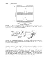
The correlation presented in FIGURE B1 shall be used in the conversion of the CPT
cone tip resistance, Qc (tsf) to SPT N-values, based on mean particle size, D
50
(mm) of
the material. The use of design parameters that are less conservative than the values
obtained from cone tip resistance to N-value correlations, and other sections of this
document, shall be statistically supported by the results of high-quality laboratory tests
and/or in-situ tests for the specific soil/rock deposits.
152
Figure B 1
REQUIRED COMPUTATIONS FOR GEOTECHNICAL REVIEW
Reports, Shop Drawings, VECP submittals, and Design-Build submittals, shall include
calculations and numerical program outputs of all the cases and loadings considered in
the design. Copies of structural calculations indicating wind loads computations and
structural deflections at the top of the wall (due to pole and panel bending) shall also be
included in the geotechnical package of computations.
153
Appendix C
Specifications and Standards
154
ASTM
Subject ASTM
Absorption and Bulk Specific Gravity of Dimension Stone C 97
Standard Test Method for Specific Gravity and Absorption of Coarse
Aggregate
C 127
Guide to Site Characterization for Engineering, Design, and
Construction Purposes
D 420
Standard Test Method for Particle-Size Analysis of Soils D 422
Test Method for Shrinkage Factors of Soils by the Mercury Method D 427
Standard Test Methods for Chloride Ion In Water D 512
Test Method for Laboratory Compaction Characteristics of Soil Using
Standard Effort (12,400 ft-lbf/ft
3
(600 kN-m/m
3
))
D 698
Standard Test Method for Specific Gravity of Soils D 854
Standard Test Methods for Electrical Conductivity and Resistivity of
Water
D 1125
Standard Test Method for Piles Under Static Axial Compressive Load D 1143
Standard Test Methods for pH of Water D 1293
Standard Practice for Soil Investigation and Sampling by Auger Borings D 1452
Test Method for Laboratory Compaction Characteristics of Soil Using
Modified Effort (56,000 ft-lbf/ft
3
(2,700 kN-m/m
3
))
D 1557
Standard Test Method for Penetration Test and Split-Barrel Sampling of
Soils
D 1586
Standard Practice for Thin-Walled Tube Geotechnical Sampling of Soils D 1587
Standard Practice for Diamond Core Drilling for Site Investigation D 2113
Standard Test Method for Unconfined Compressive Strength of
Cohesive Soil
D 2166
Standard Test Method for Laboratory Determination of Water
(Moisture) Content of Soil and Rock
D 2216
Standard Test Method for Permeability of Granular Soils (Constant
Head)
D 2434
Standard Test Method for One-Dimensional Consolidation Properties of
Soils
D 2435
Standard Classification of Soils for Engineering Purposes (Unified Soil
Classification System)
D 2487
Standard Practice for Description and Identification of Soils (Visual-
Manual Procedure)
D 2488
Standard Test Method for Field Vane Shear Test in Cohesive Soil D 2573
Standard Test Method for Triaxial Compressive Strength of Undrained
Rock Core Specimens Without Pore Pressure Measurements
D 2664
155
Subject ASTM
Standard Test Method for Unconsolidated, Undrained Compressive
Strength of Cohesive Soils in Triaxial Compression
D 2850
Standard Test Method for Unconfined Compressive Strength of Intact
Rock Core Specimens
D 2938
Standard Test Methods for Moisture, Ash, and Organic Matter of Peat
and Other Organic Soils
D 2974
Standard Test Method for Direct Shear Test of Soils Under
Consolidated Drained Conditions
D 3080
Standard Classification of Soils and Soil-Aggregate Mixtures for
Highway Construction Purposes
D 3282
Standard Test Method for Infiltration Rate of Soils in Field Using
Double-Ring Infiltrometer
D 3385
Standard Test Method for Deep, Quasi-Static, Cone and Friction-Cone
Penetration Tests of Soil
D 3441
Standard Test Method for Individual Piles Under Static Axial Tensile
Load
D 3689
Standard Test Method for Piles Under Lateral Loads D 3966
Standard Test Method for Splitting Tensile Strength of Intact Rock Core
Specimens
D 3967
Standard Test Method (Field Procedure) for Withdrawal and Injection
Well Tests for Determining Hydraulic Properties of Aquifer Systems
D 4050
Standard Test Method for Sulfate Ion in Brackish Water, Seawater, and
Brines
D 4130
Standard Test Method for One-Dimensional Consolidation Properties of
Soils Using Controlled-Strain Loading
D 4186
Standard Practices for Preserving and Transporting Soil Samples D 4220
Standard Test Methods for Maximum Index Density and Unit Weight of
Soils Using a Vibratory Table
D 4253
Standard Test Method for Minimum Index Density and Unit Weight of
Soils and Calculation of Relative Density
D 4254
Standard Test Method for Liquid Limit, Plastic Limit, and Plasticity
Index of Soils
D 4318
Standard Test Method for Density of Bentonitic Slurries D 4380
Standard Test Method for Sand Content by Volume of Bentonitic
Slurries
D 4381
Standard Test Methods for Crosshole Seismic Testing D 4428
Standard Test Methods for One-Dimensional Swell or Settlement
Potential of Cohesive Soils
D 4546
Standard Test Method for Rock Mass Monitoring Using Inclinometers D 4622
156
Subject ASTM
Standard Test Method for Laboratory Miniature Vane Shear Test for
Saturated Fine-Grained Clayey Soil
D 4648
Standard Test Method for Pressuremeter Testing in Soils D 4719
Standard Test Method for Determining Subsurface Liquid Levels in a
Borehole or Monitoring Well (Observation Well)
D 4750
Standard Test Method for Consolidated Undrained Triaxial Compression
Test for Cohesive Soils
D 4767
Standard Test Method for High-Strain Dynamic Testing of Piles D 4945
Standard Practices for Preserving and Transporting Rock Core Samples D 5079
Standard Test Method for Measurement of Hydraulic Conductivity of
Saturated Porous Materials Using a Flexible Wall Permeameter
D 5084
Standard Guide for Field Logging of Subsurface Explorations of Soil
and Rock
D 5434
Standard Guide for Using the Seismic Refraction Method for
Subsurface Investigation
D 5777
Standard Test Method for Performing Electronic Friction Cone and
Piezocone Penetration Testing of Soils
D 5778
Standard Test Method for Low Strain Integrity Testing of Piles D 5882
Standard Practice for Using Hollow-Stem Augers for Geotechnical
Exploration and Soil Sampling
D 6151
Standard Practice for the Use of Metric (SI) Units in Building Design
and Construction
E 0621
Standard Test Method for Measuring pH of Soil for Use in Corrosion
Testing
G 51
Standard Test Method for Field Measurement of Soil Resistivity Using
the Wenner Four-Electrode Method
G 57
Provisional Guide for Selecting Surface Geophysical Methods PS 78
Standard for Use of the International System of Units (SI): The Modern
Metric System
SI-10
157
AASHTO
Subject AASHTO
Standard Classification of Soils and Soil-Aggregate Mixtures for
Highway Construction Purposes
M 145
Standard Test Method for Specific Gravity and Absorption of Coarse
Aggregate
T 85
Standard Test Method for Particle-Size Analysis of Soils T 88
Standard Test Method for Liquid Limit, Plastic Limit, and Plasticity
Index of Soils
T 89
Test Method for Shrinkage Factors of Soils by the Mercury Method T 92
Test Method for Laboratory Compaction Characteristics of Soil Using
Standard Effort (12,400 ft-lbf/ft
3
(600 kN-m/m
3
))
T 99
Standard Test Method for Specific Gravity of Soils T 100
Test Method for Laboratory Compaction Characteristics of Soil Using
Modified Effort (56,000 ft-lbf/ft
3
(2,700 kN-m/m
3
))
T 180
Standard Practice for Soil Investigation and Sampling by Auger Borings T 203
Standard Test Method for Penetration Test and Split-Barrel Sampling of
Soils
T 206
Standard Practice for Thin-Walled Tube Geotechnical Sampling of Soils T 207
Standard Test Method for Unconfined Compressive Strength of
Cohesive Soil
T 208
Standard Test Method for Permeability of Granular Soils (Constant
Head)
T 215
Standard Test Method for One-Dimensional Consolidation Properties of
Soils
T 216
Standard Test Method for Field Vane Shear Test in Cohesive Soil T 223
Standard Practice for Diamond Core Drilling for Site Investigation T 225
Standard Test Method for Direct Shear Test of Soils Under
Consolidated Drained Conditions
T 236
Standard Practice for Using Hollow-Stem Augers for Geotechnical
Exploration and Soil Sampling
T 251
Pore Pressure T 252
Standard Test Method for Rock Mass Monitoring Using Inclinometers T 254
Standard Test Methods for One-Dimensional Swell or Settlement
Potential of Cohesive Soils
T 258
Standard Test Method for Laboratory Determination of Water
(Moisture) Content of Soil and Rock
T 265
Standard Test Methods for Moisture, Ash, and Organic Matter of Peat
and Other Organic Soils
T 267
Resilient Modulus – Soil T 294
158
Subject AASHTO
Standard Test Method for Unconsolidated, Undrained Compressive
Strength of Cohesive Soils in Triaxial Compression
T 296
Standard Test Method for Consolidated Undrained Triaxial
Compression Test for Cohesive Soils
T 297
Standard Test Method for High-Strain Dynamic Testing of Piles T 298
159
Florida Test Method
Subject FM
Chloride Content - Soil (Retaining wall backfill) 5-556
Standard Test Method for Sulfate Ion in Brackish Water, Seawater, and
Brines
5-553
Standard Test Methods for Chloride Ion In Water 5-552
Standard Test Methods for Electrical Conductivity and Resistivity of
Water
5-551
Standard Test Method for Measuring pH of Soil for Use in Corrosion
Testing
5-550
Test Method for Laboratory Compaction Characteristics of Soil Using
Standard Effort (12,400 ft-lbf/ft
3
(600 kN-m/m
3
))
5-525
Test Method for Laboratory Compaction Characteristics of Soil Using
Modified Effort (56,000 ft-lbf/ft
3
(2,700 kN-m/m
3
))
5-521
Florida Bearing Value 5-517
Limerock Bearing Ratio 5-515
Permeability - Falling Head 5-513
Standard Test Method for Consolidated Undrained Triaxial
Compression Test for Cohesive Soils
1-T 297
Standard Test Method for Unconsolidated, Undrained Compressive
Strength of Cohesive Soils in Triaxial Compression
1-T 296
Standard Test Methods for Moisture, Ash, and Organic Matter of Peat
and Other Organic Soils
1-T 267
Standard Test Method for Laboratory Determination of Water
(Moisture) Content of Soil and Rock
1-T 265
Standard Test Method for Direct Shear Test of Soils Under
Consolidated Drained Conditions
1-T 236
Standard Test Method for One-Dimensional Consolidation Properties of
Soils
1-T 216
Standard Test Method for Permeability of Granular Soils (Constant
Head)
1-T 215
Standard Test Method for Unconfined Compressive Strength of
Cohesive Soil
1-T 208
Standard Practice for Thin-Walled Tube Geotechnical Sampling of Soils 1-T 207
Standard Test Method for Specific Gravity of Soils 1-T 100
Test Method for Shrinkage Factors of Soils by the Mercury Method 1-T 092
Standard Test Method for Liquid Limit, Plastic Limit, and Plasticity
Index of Soils
1-T 090 &
1-T-089
Standard Test Method for Particle-Size Analysis of Soils 1-T 088
160
Subject FM
Standard Test Method for Specific Gravity and Absorption of Coarse
Aggregate
1-T 085
Standard Test Method for Density of Bentonitic Slurries 8-RP13B-1
Viscosity of Slurry 8-RP13B-2
Standard Test Method for Sand Content by Volume of Bentonitic
Slurries
8-RP13B-3
pH of Slurry 8-RP13B-4
161
Appendix D
Reference List
162
AASHTO
Manual on Subsurface Investigations, AASHTO, Washington DC, 1988.
NCHRP
Recommended Guidelines for Sealing Geotechnical Exploratory Holes, National
Cooperative Highway Research Program, NCHRP Report 378
Dunnicliff, John, Geotechnical Instrumentation for Monitoring Field Performance,
NCHRP Synthesis 89, Transportation Research Board, 1993.
TRB
M. McVay, B. Armaghani, and R. Casper; “Design and Construction of Auger-Cast Piles
in Florida” in Design and Construction of Auger Cast Piles, and Other Foundation
Issues, Transportation Research Record No. 1447, 1994
FDOT
Guidelines For Use In The Soils Investigation and Design of Foundations For Bridge
Structures In The State Of Florida, Research Report 121-A, Florida Department
of Transportation, 1967.
Rigid Pavement Design Manual, FDOT, (Current version)
Drainage Manual, Florida Department of Transportation, (Current version)
Design Standards, Florida Department of Transportation, (Current version).
Structures Design Guidelines, Florida Department of Transportation, (Current version).
Plans Preparation Manual, Florida Department of Transportation, (Current version).
FHWA
FHWA-IP-77-8 The Texas Quick-Load Method for Foundation Load Testing -
Users Manual
FHWA-TS-78-209 Guidelines for Cone Penetration Test - Performance and Design
FHWA-IP-84-11 Handbook on Design of Piles and Drilled Shafts Under Lateral
Load
FHWA-RD-86-185 Spread Footings for Highway Bridges
FHWA-RD-86-186 Prefabricated Vertical Drains Vol. I, Engineering Guidelines
FHWA HI-88-009 Soils and Foundations Workshop Manual – Second Edition
FHWA-IP-89-008 The Pressuremeter Test for Highway Applications
FHWA-RD-89-043 Reinforced Soil Structures, Volume I: Design and Construction
Guidelines
163
FHWA-SA-91-042 Static Testing of Deep Foundations
FHWA-SA-91-043 Manual on the Cone Penetrometer Test
FHWA-SA-91-044 Manual on the Dilatometer Test
FHWA-SA-91-048 Com624P – Laterally Loaded Pile Analysis Program for the
Microcomputer Version 2.0
FHWA-SA-92-045 EMBANK- A Microcomputer Program to Determine One-
Dimensional Compression Due to Embankment Loads
FHWA-SA-93-025 Geosynthetic Mechanically Stabilized Earth Slopes on Firm
Foundations
FHWA-SA-93-068 Soil Nailing Field Inspectors Manual
FHWA-SA-94-005 Advance Course on Soil Slope Stability: Volume I, Slope Stability
Manual
FHWA-SA-94-034 CBEAR - Bearing Capacity Analysis of Shallow Foundations
Users Manual,
FHWA-SA-94-035 The Osterberg CELL for Load Testing Drilled Shafts and Driven
Piles
FHWA HI-95-038 Geosynthetic Design and Construction Guidelines
FHWA-RD-95-172 Load Transfer for Drilled Shafts in Intermediate Geomaterials
FHWA-RD-96-016 thru 019 Drilled and Grouted Micropiles: State of Practice Review
Vol I – Vol IV
FHWA-HI-96-033 Manual on Design and Construction of Driven Pile Foundations
FHWA-SA-96-039 RSS Reinforced Slope Stability A Microcomputer Program User’s
Manual
FHWA-SA-96-069R Manual for Design & Construction Monitoring of Soil Nail Walls
FHWA-NHI-00-043 Mechanically Stabilized Earth Walls and Reinforced Soil Slopes
Design and Construction Guidelines
FHWA-RD-96-179 thru 181 Determination of Pile Driveability and Capacity from
Penetration Tests Vol I - Vol III
FHWA-HI-97-013 and 014 Manual on Design and Construction of Driven Pile
Foundations
FHWA-HI-97-021 Subsurface Investigations
FHWA-RD-97-130 Design Manual for Permanent Ground Anchor Walls
FHWA-HI-98-032 Load and Resistance Factor Design (LRFD) for Highway Bridge
Substructures
FHWA-HI-98-034 Geotechnical Instrumentation
164
FHWA-RD-98-065 thru 068 Summary Report of Research on Permanent Ground
Anchor Walls
FHWA-IF-99-025 Drilled Shafts: Construction Procedures and Design Methods
FHWA-RD-99-170 Extrapolation of Pile Capacity From Non-Failed Load Tests
Geotechnical Engineering Circular No. 1 Dynamic Compaction
Geotechnical Engineering Circular No. 2 Earth Retaining Systems
Geotechnical Engineering Circular No. 4 Ground Anchors and Anchored Systems
Geotechnical Engineering Circular No. 5 Evaluation of Soil and Rock Properties
Geotechnical Engineering Circular No. 7 Soil Nail Walls
Geotechnical Engineering Notebook, GT #1 Guidelines for the Design of Mechanically
Stabilized Earth Walls (Inextensible
Reinforcements)
“Checklist and Guidelines for Review of Geotechnical Reports and Preliminary Plans
and Specifications”
Military
NAVFAC DM-7.1 - Soil Mechanics, Department of the Navy, Naval Facilities
Engineering Command, 1986.
NAVFAC DM-7.2 - Foundations and Earth Structures, Department of the Navy, Naval
Facilities Engineering Command, 1986.
Engineering Classification and Index Properties for Intact Rock Technical Report No.
AFWL-TR-65-116, Air Force Weapons Laboratory, New Mexico, 1966.
Geophysical Exploration for Engineering and Environmental Investigations, Engineering
Manual 1110-1-1802, Department of Army, U.S. Army Corps of Engineers, 1995
Other Federal
U.S. Environmental Protection Agency, Land Treatment of Municipal Wastewater -
Process Design Manual, 1981.
Earth Manual, US Department of Interior, Bureau of Reclamation, US Government
Printing Office, Washington, D.C., 1994.
Misc.
Marchetti, Silvano, In-Situ Tests by Flat Dilatometer, Journal of the Geotechnical
Engineering Division, ASCE, Vol. 106, No. GT3, March 1980.
165
Baldi, G., Bellotti R., Ghionna, V., Jamiolkowski, M., Marchetti, S. and Pasqualini, E.
Flat Dilatometer Tests in Calibration Chambers, Use of Insitu Tests in Geotechnical
Engineering, ASCE Specialty Conference, Geotechnical Special Publication No. 6,
1986.Schmertmann, John, Suggested Method for Performing the Flat Dilatometer
Test, Geotechnical Testing Journal, ASTM, Vol. 9, No. 2, June 1986.
Standards For Onsite Sewage Disposal Systems, Rules of the Department of Health and
Rehabilitative Services, Chapter 10 D-6, Florida Administrative Code.
Lambe, T. William, Soil Testing for Engineers, John Wiley & Sons, Inc. New York, NY,
1951.
Fang, Hsai-Yang, Foundation Engineering Handbook, Second Edition, Van Nostrand
Reinhold Company, New York, 1990.
Dunnicliff, John, Geotechnical Instrumentation for Monitoring Field Performance,
Wiley-Interscience, New York, 1993.
Duncan, J.M. & Buchignani, A.L., An Engineering Manual for Settlement Studies,
Department of Civil Engineering, University of California, Berkeley, 1976.
Goble, G.G. & Rausche, Frank, GRLWEAP, Wave Equation Analysis of Pile
Foundations, GRL & Associates, Inc., 1991.
Pile Driving Analyzer Manual, PAK , Pile Dynamics, Inc., Cleveland, Ohio, 1997