Fundamentals of Clinical Ophthalmology - part 4 pdf
Bạn đang xem bản rút gọn của tài liệu. Xem và tải ngay bản đầy đủ của tài liệu tại đây (503.94 KB, 23 trang )
PHACOEMULSIFICATION TECHNIQUE
55
Chopping techniques
“Nagahara chop” (horizontal chopping)
Nagahara
15
was the first to report nuclear
disassembly using chopping and described a
technique that does not require sculpting. This
is therefore also known as “non-stop chop” or
“pure chop”. Because the chopper passes from
the periphery toward the centre of the lens, it is
classified as a type of horizontal chopping
technique. Good hydrodissection is required
and, like for most chopping techniques,
hydrodelamination is beneficial.
Nagahara chop employs a 0–15° phaco tip and
high vacuum. A short burst of ultrasound
is first used to impale and grip the nucleus
(Figure 5.16a). The lens is then drawn slightly
toward the surgeon as the chopper is inserted
under the rhexis edge and around the periphery of
the nucleus. The chopper is next pulled through
the lens toward the phaco tip (Figure 5.16b). Just
before contact between the two instruments is
made, they are slightly separated to propagate a
fracture through the entire lens (Figure 5.16c).
The lens–nucleus complex is next rotated
approximately 30° (clockwise in the case of a
surgeon holding the phaco hand piece in his right
hand), reimpaled by the phaco probe, and
chopped in the same manner (Figure 5.16d). A
small wedge-shaped segment of nucleus held by
the phaco probe is thus broken off the main
nucleus. By maintaining high vacuum this is then
moved into the central safe zone of the capsular
bag, where it is phacoemulsified (Figure 5.16e).
The process is then repeated (Figure 5.16f) until
the entire nucleus is removed.
“Quick chop” (vertical chopping)
This differs from the technique described by
Nagahara by using a modified chopper to
penetrate the nucleus vertically while it is held
by the phaco probe (Figure 5.17a). Upward
force simultaneously applied to the lens by the
probe results in shearing forces that create a
fracture (Figure 5.17b). This fracture is further
propagated by also slightly separating the two
instruments. The method has the advantage that
the chopper is not placed under the capsule at
the periphery of the nucleus, but is positioned
within the capsular rhexis adjacent to the buried
phaco probe. This is particularly advantageous
where little epinucleus exists, in which case
placement of the Nagahara chopper may cause
b)
a)
Figure 5.15 The “Bowl technique”. (a) Debulking
the nucleus to create a bowl. (b) Removal of the bowl.
capsule damage. However, quick chop does rely
on brittle, relatively hard lenses for the fracture
to propagate, and may be difficult to perform in
eyes with deep anterior chambers or with a small
capsulorhexis.
Although vertical and horizontal chopping
techniques can be employed as distinct entities
(Table 5.2), elements of each are often combined.
For example, as the chopper approaches the tip
of the phaco probe using a Nagahara Chop
technique, the fracture may best be propagated
by separating the instruments, and elevating the
impaled lens and pressing posteriorly with the
chopper.
CATARACT SURGERY
56
a)
c)
e) f)
b)
d)
Figure 5.16 “Nagahara chop”. (a) The nucleus is impaled by the phaco probe, held with vacuum, and
withdrawn to facilitate positioning the chopper (tilted to go beneath the rhexis). (b) The chopper is drawn
alongside the phaco tip. (c) Separating the chopper and phaco tip propagates the first fracture. (d) After rotating,
the chopping process is repeated to generate a second fracture. (e) The liberated fragment, which continues to
be held with vacuum, is drawn into the central rhexis area and emulsified. (f) The remaining nucleus is again
rotated to position the nucleus for the next chop.
“Stop and chop”
This method is a variation of the Nagahara
chop that provides space within the capsular bag
for nuclear manipulation and aids removal of the
first lens fragment. Although hydrodissection is
essential, stop and chop may be performed
without hydrodelamination. In this technique,
described by Dr Paul Koch,
27
a central trench is
first sculpted and the nucleus is cracked into two
halves, or heminuclei (Figure 5.18a). The surgeon
next “stops” sculpting and starts “chopping”.
After dividing the nucleus, the fractured
nuclear complex is rotated through 90° and the
vacuum is increased to approximately 100 mmHg.
The phaco tip is then engaged into the
heminucleus at about half depth, using a short
burst of ultrasound (Figure 5.18b). The vacuum
is maintained, and this allows the gripped
heminucleus to be drawn centrally and upward
into the rhexis plane. The chopping second
instrument is passed out to the lens periphery,
around the nucleus, and is then drawn toward
the phaco tip (Figure 5.18c). Separating the two
instruments liberates a fragment from the main
body of the lens, which is easily phacoemulsified
PHACOEMULSIFICATION TECHNIQUE
57
a)
b)
Figure 5.17 “Vertical chop”. (a) The nucleus is
stabilised by the impaled phaco probe, and as the
chopper vertically penetrates the nucleus a vertical
separation force is applied. (b) A fracture is created
through the nucleus.
a) b)
d)c)
Figure 5.18 “Stop and chop”. (a) Cracking the lens
along the single groove to create two heminuclei.
(b) Gripping the distal heminucleus after the
lens–nucleus complex has been rotated and drawing it
into the “central safe zone” of the capsular bag while
the chopper is positioned. (c) Performing the chop.
(d) Phacoemulsifying the chopped lens fragment.
Table 5.2 Relative indications for horizontal and
vertical chopping techniques
Horizontal chopping Vertical chop (for example,
(for example, “Nagahara “Quick chop”)
chop”)
Deep anterior chamber Difficulty visualising rhexis
edge
Moderately dense nuclei Dense brittle nuclei
Small rhexis Little epinucleus
(Figure 5.18d). The process is repeated and
continued until the first heminucleus is
removed. The remaining half is rotated and the
same technique is applied.
“Phaco slice”
Another variation of chopping was described by
David Gartry of Moorfields Eye Hospital (Video
presentation, Royal College of Ophthalmologists
Annual Congress, 2000). This uses a very safe
horizontal slicing action with a blunt second
instrument and reduces the risk of rhexis or
capsule damage. The first part of the procedure
is exactly as for stop and chop. Once the two
heminuclei are completely separated, relatively
high vacuum is used to engage and then pull the
distal end of a heminucleus out of the bag and
into the plane of the rhexis/pupil (Figure 5.19a).
The second instrument (either a manipulator of
an iris repositor) is next directed in a horizontal
plane across the anterior chamber, slicing a
fragment from the heminucleus (Figure 5.19b).
This is then phacoemulsified and the process
repeated.
Learning chopping techniques
Many of the principles of learning
phacoemulsification discussed in Chapter 1 are
also relevant when making the transition from
techniques such as divide and conquer to those
that involve chopping. Patient selection is
particularly important, and the features that make
a case ideal for learning phacoemulsification
(Table 1.4) also apply to developing chopping
skills. Although hard nuclei are usually more
efficiently dealt with using a chopping technique,
these lenses are nonetheless difficult to chop and
are not suitable when learning.
A structured approach to learning chopping is
necessary, and where possible relevant courses
and practical sessions should be attended. A
proficient divide and conquer technique is the
ideal starting point for learning to chop. In the
first instance it is possible to practice chopping
once the lens has been divided in quadrants
using a divide and conquer technique. Early in
the learning phase chopping is best tried after
one quadrant has already been removed in the
standard manner and the second quadrant can
easily be drawn into the central safe zone of the
capsular bag. The anxiety experienced when a
sharp and hooked chopper (Figure 5.9) is first
inserted into the eye may be avoided by using
the second instrument to chop the quadrant in a
method similar to “phaco slice’’. This helps to
develop the bimanual skills and confidence to
proceed to more complex techniques using
chopping instruments. At all times the divide
and conquer method can safely be returned to in
order to complete the procedure. The next step
is to perform a stop and chop or phaco slice
technique, in which reverting to divide and
conquer” is still relatively straightforward. Once
these techniques are mastered, progressing to
Nagahara chop or quick chop is then possible,
provided the case is favourable.
Troubleshooting when chopping
Gripping the nucleus Maintaining sufficient
grip on the nucleus is essential to performing an
CATARACT SURGERY
58
a)
b)
Figure 5.19 “Phaco slice”. (a) Drawing the gripped
heminucleus up into the plane of the rhexis.
(b) Slicing with the second instrument.
efficient chop. Adequate vacuum settings should
be used and these will vary between machines.
Initially, a setting similar to that used during the
quadrant removal stage of a divide and conquer
technique will usually be sufficient, but with
experience higher levels may be used (Table
5.1). Exposing more of the phaco needle by
moving the irrigation sleeve up the hand piece
ensures that the probe can be driven deeper into
the nucleus and provides a better hold on the
lens (Figure 5.20b). Grip can also be improved
by using a burst phaco mode and a phaco tip
with a narrow angle (< 30°), which is more
easily occluded.
During the early stages of most chopping
techniques it is possible to displace the impaled
lens from the phaco tip while positioning the
chopper. Learning this manoeuvre is particularly
difficult because of the need to maintain high
vacuum with the foot pedal and keep the
dominant hand stationary while manipulating
the chopper with the non-dominant hand.
Placing the chopper in position before impaling
the lens on the phaco probe is much easier and
has the added advantage that it then stabilises
the lens while the phaco probe is driven into
the nucleus.
Avoiding capsule damage The primary
concern during the learning phase of chopping is
the risk of damaging the anterior capsule with
the chopper. If a technique such as stop and
chop is used, then chopping predominantly
takes place in the central capsular bag and
reduces this risk. When sufficient epinucleus
exists, placing the chopper out to the equatorial
aspect of the nucleus is relatively safe and the
vertical portion of the chopper can easily be seen
as it passes through the peripheral lens. In
contrast, with large dense nuclei, in which little
epinucleus is present, placement of the chopper
can be difficult. The vertical portion of the
chopper must be rotated to lie horizontally as it
is introduced under the rhexis. If the chopper is
thought to be anterior to the capsule then the
rhexis should be examined as the instrument is
gently moved. The rhexis should not move if the
chopper is correctly placed. In circumstances in
which the red reflex is poor the use of a capsule
stain (see Chapter 3) greatly improves visualisation
of the capsule and helps with safe positioning of
the chopper.
Although most choppers have protected tips
and pose relatively little risk to the posterior
capsule in the initial phases of chopping, some
may become sharp after contact with other
instruments. During the learning curve, eyes
with small pupils should be avoided because
the tip of the chopping instrument may not
easily be visualised at the peripheral edge of the
lens. With experience, however, chopping can be
performed despite a reduced view. The period of
highest risk of damage to the posterior capsule is
during the removal of the final pieces of the lens.
PHACOEMULSIFICATION TECHNIQUE
59
Figure 5.20 Position of the irrigating sleeve.
(a) Sculpting techniques. (b) Chopping techniques.
a)
b)
Sudden postocclusion surge may bring the
capsule into contact with the chopper, and
replacing it with a blunt second instrument at
this stage may be advisable. This instrument can
then be placed under the final fragment as it is
emulsified to prevent accidental aspiration of the
capsule into the phaco probe (Figure 5.14). It is
then also in position for removal of the
epinucleus.
Failure to chop When using a Nagahara
chopping technique a common mistake is to enter
the lens with the phaco probe at the centre of the
rhexis. This causes the buried tip to lie in the
relative periphery of the lens and chopping does
not occur at the central nucleus (Figure 5.21a).
The entry of the phaco probe into the lens should
therefore be initiated as close as possible to the
subincisional aspect of the rhexis, ensuring that
the phaco tip then becomes located close to the
centre of the lens (Figure 5.21b).
As previously mentioned, a combination of
vertical and horizontal movements with the
chopper may be required to propagate a fracture
within the nucleus, and these may have to be
repeated.
Fracturing advanced brunescent lenses may be
particularly difficult unless they are brittle. The
optimal chopping technique to use in these
circumstances is open to debate. The main
problem is failure to crack the central posterior
region of the lens. As the instruments are
separated, lens fibre bridges may be visible against
the red reflex in the posterior aspect of the fracture.
Advancing the chopper into the crack may allow
these to be individually cut, but there is a risk of
posterior capsule damage and the surgeon should
proceed with care. In some cases a dense posterior
plate of lens may remain, and replacing the phaco
probe with a second chopper or similar instrument
allows this to be chopped with a bimanual
technique. Viscoelastic injected under the plate
also helps to manoeuvre the plate so that it can be
either broken up or directly phacoemulsified.
Removing the first segment The
difficulty in “unlocking” the first segment or
fragment chopped from the nucleus when using
a Nagahara Chopping technique led to
development of methods in which space was first
created (such as Stop and chop). However, when
the nucleus is efficiently chopped, removing a
segment should be possible assuming adequate
vacuum is used. If, after the initial two chops,
the first segment cannot be extracted, then after
rotating the lens a further chop can be made in
an attempt to liberate an adjacent segment. If
this also fails then the lens can again be rotated
and the procedure repeated until a fragment is
extracted and emulsified. Alternatively, the
chopper can be used to help dislocate a fragment
centrally. Once one fragment is removed the
space created allows the others to follow easily.
CATARACT SURGERY
60
a)
b)
Figure 5.21 Positioning the phaco probe during
“Nagahara chop”. (a) Incorrect: phaco tip in the
peripheral lens. (b) Correct: phaco tip in the central
nucleus.
When chopping hard lenses, creating small
segments may make it easier to liberate the
fragments. To further facilitate segment removal,
and minimise the ultrasound power used, the
extracted segment can be chopped again and
forced (or “stuffed”) into the aspiration port of
the phaco probe.
28
Removing the epinucleus Hydrodelamination
produces an epinuclear layer that maintains a
protective barrier between the instruments and
the capsule while the nucleus is chopped and
phacoemulsified. The surgeon is then faced with
removing the epinucleus, which, even when soft,
can be time consuming if it is removed as part of
the lens cortex aspiration. This has similarities to
removing the soft peripheral lens when using a
bowl technique (Figure 5.15). In most
circumstances the phaco probe, with its large
aspiration port, is used but little or no
ultrasound is required. The epinucleus is first
engaged using moderately high vacuum in the
region of the peripheral anterior capsule
opposite the main incision. It is then drawn
centrally and, using a bimanual technique, the
epinucleus located over the posterior capsule is
swept away from the incision using a second
instrument. Simultaneously, the vacuum is
increased using the foot pedal and the
epinucleus is aspirated. Hence the epinucleus is
fed back on itself and removed in one piece.
Debulking the epinucleus may facilitate this
manoeuvre but an adequate peripheral piece of
epinucleus should be retained to allow it to be
aspirated and initiate the manoeuvre. If a plate
of posterior epinucleus is difficult to remove,
then viscoelastic placed behind it will move it
anteriorly and allow safe aspiration.
Cortex aspiration
Following successful phacoemulsification,
and despite cortical cleaving hydrodissection,
remnants of cortical lens (soft lens matter)
almost invariably remain. Thorough removal of
the lens cortex (“cortical clean up”) reduces the
risk of postoperative lens related inflammation
and the incidence of posterior capsule
opacification.
2
It may be removed using either
manual or automated systems, both of which
simultaneously maintain the anterior chamber
by gravity-fed fluid infusion and permit
aspiration of soft lens matter. Manual systems
use a hand held syringe to generate vacuum
(Figure 5.22) whereas an automated system
produces vacuum that is controlled by the foot
pedal. All manual systems and most automatic
systems use a coaxial irrigation and asiration
cannula or hand piece.
Technique
By aspirating under the anterior lens capsule
cortical lens matter is engaged, and this is then
drawn centripetally and aspirated (Figure 5.23).
It is important that aspiration is not commenced
until the port is placed into the periphery of the
capsular bag. This ensures that the port is fully
occluded and the cortex is gripped. Care has to
be taken, however, to ensure that the capsule is
not engaged. If this is suspected then the
aspiration should be reversed. An advantage of a
manual syringe system is that this can be done
very quickly. Automatic systems regurgitate
PHACOEMULSIFICATION TECHNIQUE
61
Figure 5.22 Manual syringe system for cortex
aspiration (Simcoe).
aspirated fluid by reversing the pump, which is
controlled by a switch on the foot pedal.
Assuming only cortex is engaged the process of
aspiration is repeated around the circumference
of the capsular bag. Using the main incision it is
relatively easy to access the majority of the bag
with either a straight, curved, or 145° angled
(Figure 5.24a) instrument. However, the
subincisional cortex is more difficult to remove
because the instrument disorts the cornea in this
area. Many phaco systems with automatic
aspiration have an interchangeable 90° angled tip
(or “hockey stick”; Figure 5.24b) that can be
used to remove the cortex in this region.
31
An
alternative is to enlarge the existing second
instrument paracentesis (Figure 5.25) or to create
a second paracentesis to accommodate the
irrigation and aspiration instrument.
32
To avoid
this additional surgical step, the second
paracentesis may be deliberately oversized at the
beginning of surgery. Unfortunately, this may
lead to leakage of irrigation fluid around the
second instrument during phacoemulsification (a
particular problem if a shallow anterior chamber
already exists). Using the second instrument
paracentesis also usually necessitates using the
irrigation and aspiration instrument in the non-
dominant hand. A bimanual technique with
separate infusion and aspiration cannulas allows
improved access to the subincisional cortex
without enlarging the second instrument
paracentesis (Figure 5.26).
33
The two
instruments also stabilise the globe and, if
necessary, enable the iris to be retracted,
improving visualisation of the capsular bag
(Box 5.1). If both instruments have the same
external diameter and one is used through the
main incision, then substantial leakage of
CATARACT SURGERY
62
a)
b)
Figure 5.23 Cortex aspiration technique. (a) Engaging
cortex in the peripheral capsular bag. (b) Stripping
and aspirating cortex.
Figure 5.24 Automated hand piece instruments
(Allergan). (a) 145° tip. (b) 90° tip.
a)
b)
irrigation fluid may occur. An additional
paracentesis is therefore recommended for the
second cannula, and this allows each instrument
to be used in either hand.
Small fragments of nucleus that have not
been phacoemulsified may be discovered during
cortical aspiration. Using a manual system these
cannot usually be aspirated and the phaco tip
should be reintroduced into the eye. A coaxial
automated system allows a second instrument to
be placed into the anterior chamber, which can
then be used to break up the fragment against
the aspiration port. When a bimanual technique
is used the irrigation instrument can be used
against the aspiration instrument in a similar
manner.
The irrigation and aspiration equipment can
also be used to remove or “polish” lens epithelial
cells from the anterior capsule using low levels of
vacuum. This capsule polishing may prevent
anterior capsule opacity or phimosis, which is
associated with, for example, silicone plate haptic
lenses.
34
Posterior capsule plaques should be
approached with care because it is possible to
cause vitreous loss. During capsule polishing,
aspiration is often unnecessary and several single
lumen cannulas are available that can be attached
to the gravity-fed infusion (Figure 5.27). The
external surface of these cannulas are textured
or have a soft flexible sleeve to allow the plaque to
be gently abraded. The aspiration cannulas of
some bimanual systems are similarly treated so
further instrumentation is unnecessary. Bimanual
PHACOEMULSIFICATION TECHNIQUE
63
a)
b)
Figure 5.25 Using the paracentesis to access the
subincisional cortex. (a) Cortex is engaged in the
peripheral capsular bag. (b) Cortex is stripped and
aspirated in the “central safe zone”.
Figure 5.26 Bimanual irrigation and aspiration
instruments (BD Ophthalmic Systems).
Box 5.1 Advantages of bimanual
irrigation and aspiration
• Entire capsular bag accessible
• Easy access to subincisional cortex
• Simultaneous retraction of iris possible
• Stabilisation of globe
• Capsule polishing without additional
instrumentation
• Residual nuclear fragments easily broken up
and aspirated
systems also have the advantage that all of the
capsular bag can be accessed easily.
Complications: avoidance and
management
The process of cortical clean up can cause both
capsule rupture and zonule dehiscence. If the
cortex seems particularly adherent, it is
important to be patient. With time the cortical
matter hydrates and should become easier to
remove. Inserting the intraocular lens and
rotating it can help to liberate cortex but the
haptics, like a capsular tension ring, may also
trap cortical matter in the equatorial capsular
bag and make it difficult to aspirate.
Most concern during irrigation and aspiration
centres on removal of the subincisional cortex.
When using a 90° tip, the instrument should be
held as close to vertical as is possible without
distorting the cornea (Figure 5.28a). Once the
tip is within the capsular bag, rotating the
instrument swings the aspiration port under
the rhexis toward the peripheral subincisional
capsular bag (Figure 5.28b). The aspiration port
thus remains in view and aspiration can then be
commenced to engage the cortex. Once vacuum
has built up the instrument is gently rotated
back to its original position, stripping cortex.
This piece of cortex can then be fully aspirated
in the safe central zone (Figure 5.28c). If a 90°
angle tip is found to distort the view of the
anterior segment, then this problem may be
reduced in the future by altering the
construction and length of the incision (see
CATARACT SURGERY
64
Figure 5.27 Capsule polishing cannulas (BD
Ophthalmic Systems).
a)
b)
c)
Figure 5.28 Using the 90° tip. (a) Near vertical
position of the hand piece within the eye. (b)
Accessing the subincisional capsular bag by rotating
the tip under the rhexis. (c) Aspiration of stripped
cortex after rotating tip back to “central safe zone”.
Chapter 2). Alternatively, a bimanual system can
be used or a separate paracentesis employed.
In eyes with known zonule damage cortex
aspiration needs to proceed with caution (see
Chapter 10). It should commence in areas of
normal zonule support and initially avoid areas
of dialysis. Stripping of aspirated cortex should
employ tangential rather than radial movements,
and where possible it should be directed toward
the areas of weakness.
References
1 Fine IH. Cortical cleaving hydrodissection. J Cataract
Refract Surg 1992;18:508–12.
2 Peng Q, Apple DJ, Visessook N, et al. Surgical
prevention of posterior capsule opacification. Part 2:
enhancement of cortical cleanup by focusing on
hydrodissection. J Cataract Refract Surg 2000;26:
188–97.
3 Gimbel HV. Hydrodissection and hydrodelineation. Int
Ophthalmol Clin 1994;34:73–90.
4 Ota I, Miyake S, Miyake K. Dislocation of the lens
nucleus into the vitreous cavity after standard
hydrodissection. Am J Ophthalmol 1996;121:706–8.
5 Miyake K, Ota I, Ichihashi S, Miyake S, Tanaka Y,
Terasaki H. New classification of capsular block
syndrome. J Cataract Refract Surg 1998;24:1230–4.
6 Yeoh R. The “pupil snap” sign of posterior capsule
rupture with hydrodissection in phacoemulsification
[letter]. Br J Ophthalmol 1996;80:486.
7 Shepherd JR. In situ fracture. J Cataract Refract Surg
1990;16:436–40.
8 Davison JA. Hybrid nuclear dissection technique for
capsular bag phacoemulsification. J Cataract Refract
Surg 1990;16:441–450.
9 Gimbel HV. Divide and conquer nucleofractis
phacoemulsification: development and variations.
J Cataract Refract Surg 1991;17:281–91.
10 Pacifico RL. Divide and conquer phacoemulsification:
one-handed variant. J Cataract Refract Surg 1992;
18:513–7.
11 Johnson SH. Split and lift: nuclear quadrant
management for phacoemulsification. J Cataract Refract
Surg 1993;19:420–4.
12 Fine IH, Maloney WF, Dillman DM. Crack and flip
phacoemulsification technique. J Cataract Refract Surg
1993;19:797–802.
13 Gimbel HV, Chin PK. Phaco-sweep. J Cataract Refract
Surg 1995;21:493–6.
14 Corydon L, Krag S, Thim K. One-handed
phacoemulsification with low settings. J Cataract Refract
Surg 1997;23:1143–8.
15 Nagahara K. Phaco-chop technique eliminates central
sculpting and allows faster, safer phaco. Ocular Surgery
News 1993;October:12–3.
16 Arshinoff SA. Phaco-slice and separate. J Cataract
Refract Surg 1999;25:474–8.
17 Hayashi K, Nakao F, Hayashi F. Corneal endothelial
cell loss after phacoemulsification using nuclear cracking
procedures. J Cataract Refract Surg 1994;20:44–7.
18 Pirazzoli G, D’Eliseo D, Ziosi M, Acciari R. Effects of
phacoemulsification time on the corneal endothelium
using phacofracture and phaco-chop techniques.
J Cataract Refract Surg 1996;22:967–9.
19 DeBry P, Olson RJ, Crandall AS. Comparison of energy
required for phaco-chop and divide and conquer
phacoemulsification. J Cataract Refract Surg 1998;
24:689–92.
20 Ram J, Wesendahl TA, Auffarth GU, Apple DJ.
Evaluation of in situ fracture versus phaco-chop
techniques. J Cataract Refract Surg 1998;24:1464–8.
21 Maloney WF, Dillman DM, Nichamin LD.
Supracapsular phacoemulsification: a capsule-free
posterior chamber approach. J Cataract Refract Surg
1997;23:323–8.
22 Ayoub MI. Three phase phacoemulsification. J Cataract
Refract Surg 1998;24:592–4.
23 Hara T, Hara T. Endocapsular phacoemulsification and
aspiration (ECPEA): recent surgical technique and
clinical results. Ophthalmic Surg 1989;20:469–75.
24 Anis AY. Hydrosonic intercapsular piecemeal
phacoemulsification or the “HIPP” technique. Int
Ophthalmol 1994;18:37–42.
25 Joo C-K, Kim YH. Phacoemulsification with a bevel-
down phaco tip: phaco-drill. J Cataract Refract Surg
1997;23:1149–52.
26 Kohlhaas M, Klemm M, Kammann J, Richard G.
Endothelial cell loss secondary to two different
phacoemulsification techniques. Ophthalmic Surg Lasers
1998;29:890–95.
27 Koch PS, Katzen LE. Stop and chop phacoemulsification.
J Cataract Refract Surg 1994;20:566–70.
28 Vasavada AR, Desai JP. Stop, chop, chop and stuff.
J Cataract Refract Surg 1996;22:526–9.
29 Dada T, Sharma N, Dada VK, Vajpayee RB. Modified
phacoemulsification in situ. J Cataract Refract Surg
1998;24:1027–9.
30 Dada T, Sharma N, Dada VK. Petalloid
phacoemulsification. Ophthalmic Surg Lasers 2000;31:
170–2.
31 Hagan JC III. Irrigation/aspiration handpiece with
changeable tip for cortex removal in small incision
phacoemulsification. J Cataract Refract Surg 1992;18:
318–20.
32 Hagan JC III. A new cannula for removal of 12 o’clock
cortex through a sideport corneal incision. Ophthalmic
Surg 1992;23:62–3.
33 Colvard DM. Bimanual technique to manage
subincisional cortical material. J Cataract Refract Surg
1997;23:707–9.
34 Joo CK, Shin JA, Kim JH. Capsular opening contraction
after continuous curvilinear capsulorhexis and
intraocular lens implantation. J Cataract Refract Surg
1996;22:585–90.
PHACOEMULSIFICATION TECHNIQUE
65
66
Improvements in surgical techniques have
provided an added impetus to improve the
precision of lens implant power calculation.
Determination of the lens implant power to give
any desired postoperative refraction requires
measurement of two key variables:
• The anterior corneal curvature in two
orthogonal meridia
• The axial length of the eye.
These measurements are then entered into an
appropriate formula.
Anterior corneal curvature
measurement
The cornea acts as a mirror reflecting the
images of luminous objects, and it is the curvature
of the “mirror” that is measured when using a
keratometer. The anterior cornea is not uniformly
curved but in most individuals progressively
flattens in the periphery.
1
The corneal apex is
also slightly decentred. Keratometers measure
anterior corneal curvature over a small annular
zone and assume that this is spherical. The size of
this zone varies with corneal curvature but
generally lies between 2 and 4 mm in diameter.
2
Contact lenses should be removed at least 48
hours before keratometry because their long-
term use can induce a reversible corneal
flattening (~0·05 mm). If the contact lens fit is
tight then this distortion or warpage may be
more pronounced, especially with rigid
polymethylmethacrylate (PMMA) lenses. In
such circumstances removal of the contact
lenses 6 weeks before biometry is ideal although
rarely practical for most individuals.
Keratometry “setup”
The room lighting should be adjusted to
avoid stray reflections on the cornea. The
keratometer’s telescopic eyepiece should be
focused for the examiner’s eye, before the
examination begins, using the in-built graticule
designed for this purpose. Failure to focus the
eyepiece in certain instruments could lead to
errors in measurement of corneal radius of
curvature of the order of 0·05 mm and as great
as 0·15 mm in some instruments.
3
Individuals
are usually examined in a seated position with
their chin on a rest and their forehead placed
against a band. If the patient’s upper eyelid
drops to within a few millimetres of the corneal
apex then it may be necessary for the examiner
to raise the eyelid, carefully avoiding indentation
of the globe and artefactually steepening the
cornea.
Manual keratometers
A central fixation target within the instrument
is provided and must be viewed by the patient. If
the individual is unable to see the fixation light,
then it is vital to fixate the fellow eye. Internally
illuminated targets (the mires) are mounted on a
6 Biometry and lens implant
power calculation
viewing telescope and their reflections on the
cornea, viewed through the keratometer’s
telescopic system, are then centred in the field of
view by the examiner. In order to overcome any
eye movements by individuals undergoing
examination, doubling devices such as prisms are
incorporated into the viewing telescope. The
instrument is set to read the corneal curvature
when two halves of a mire image just touch or
when two identical mire images are superimposed.
While the examiner adjusts the mire image
separation with one hand, the focus of the mire
reflections should be monitored continuously and
adjusted by altering the separation between the
telescope and the patient’s eye using a joystick
controlled with the other hand. The corneal image
size of the mires is related to corneal curvature
by Newton’s magnification equation, but for
accuracy instruments are calibrated against steel
spheres of known curvature. Some instruments
measure to 0·05 mm and others to 0·01 mm.
Reproducibility of measurements is within
0·05 mm.
4
Some instruments require the
telescope to be rotated through 90° to take an
orthogonal reading of corneal curvature (two-
position keratometer), whereas others permit two
orthogonal readings to be taken with the telescope
stationary (one-position keratometer).
Instruments generally have two scales, one
giving the corneal radius of curvature in
millimeters and the other giving corneal power
in dioptres (D). Currently, most but not all
instruments use a hypothetical corneal refractive
index of 1·3375 to calculate corneal power that
takes into account the small minus power of the
posterior corneal surface. Gullstrand, however,
has shown that a refractive index of 1·333
produces a more accurate estimate of corneal
power, and some practitioners elect to use this
value in lens implant power formulae. Corneal
power can be calculated from Equation A in
Appendix I.
The angles at which keratometer readings are
taken should be noted because surgeons may
decide intentionally to induce corneal flattening
in a meridian to reduce corneal astigmatism.
Flattening in the steep meridian is associated
with some steepening in the orthogonal meridian
(known as coupling), although the flattening
exceeds the steepening.
5
Arcuate keratotomy
therefore induces a hyperopic shift dependent
upon the degree of corneal coupling (typically
0·25 times the intended correction). In practice,
approximately 0·25 D should be subtracted
from the average preoperative corneal power for
each 1 D of astigmatism to be corrected (otherwise
there is a risk of residual hypermetropia).
Automatic keratometers
Automatic keratometers have the advantage
of virtually eliminating operator subjectivity.
However, it is very important to confirm that the
patient is fixating correctly, and in some
automatic keratometers it is difficult to view the
eye directly. The mires of automated keratometers
are generally light emitting diodes and the
corneal image positions of the mires are detected
using solid state detectors. The fast response of
such detectors overcomes problems associated
with eye movement, thus negating the need for
doubling devices.
Hand-held keratometers
Portable hand-held keratometers can be used
with patients in seated, standing, or supine
positions, and therefore are ideal for use on
infants, individuals with restricted physical
mobility, or those supine under general
anaesthesia. Highly accurate hand-held automatic
keratometers are now commercially available.
However, care must be taken to hold the
instrument parallel to the plane of the face, and
to check that the eye is fixating correctly and that
the eyelids do not obscure the cornea.
Difficult and complex keratometry
Poor fixation
The examiner should ensure that the patient
is fixating on the target light by observing the
BIOMETRY AND LENS IMPLANT POWER CALCULATION
67
patient’s eye and the reflections of ocular
structures viewed both directly and through the
keratometer eyepiece. The radius of curvature of
the cornea increases in the periphery by
approximately 0·5 mm at 3 mm nasal to the
corneal apex and 0·4 mm at 3 mm temporal to
the apex.
6
If measurements are taken when the
patient is not fixating correctly then large errors
will be encountered. When fixation is not
possible a target for the fellow eye should be
used. Poor fixation by the patient is the major
source of keratometry error.
Poor tear film
If the tear film constantly breaks up then it
may be necessary to insert a drop of normal
saline to clear the film for the few seconds
required for a measurement to be taken. More
viscous substances such as methylcellulose
should be avoided because they produce random
curvature readings.
Nystagmus
The keratometer should be roughly aligned
and then the patient should be asked to close
their eyes for 10 seconds. The nystagmus is
generally reduced on initial opening of the eyes,
which allows fine adjustment of the mire
separation.
Combined corneal graft
and cataract surgery
In eyes that are to be treated with combined
cataract extraction and keratoplasty, some
surgeons assume an average postoperative
anterior corneal curvature of 7·60 mm on the
basis that successful grafts tend to have a steeper
rather than a flatter curvature. Other surgeons
assume an average keratometry value of
7·80 mm. If keratometry is possible then some
surgeons use these measured values in the lens
implant power calculation and try to maintain
the corneal curvature. Keratometry readings
from the fellow eye are also sometimes used and
amended according to the corneal donor button
size. Binder
7
suggests that a corneal donor
button 0·25 mm larger than the recipient
trephine reduces the chance of corneal flattening,
whereas 0·5 mm larger induces steepening
associated with a 1–2 D myopic shift post-
operatively. Less postoperative steepening is
associated with larger grafts (7·5–8·0 mm).
Following refractive surgery
It has been reported that keratometric
measurements following refractive surgery
show a significantly smaller refractive change
than the optometric refraction.
8–11
Consequently,
the use of postkeratotomy keratometric readings
in lens implant formulae may lead to large
postoperative refractive errors. Some surgeons
use corneal topography (see below) and select a
smoothing algorithm over the pupillary zone to
determine an effective corneal power. Two other
methods for determining the true effective
corneal power following refractive surgery have
been suggested:
9
• The known refractive history method
• The contact lens method.
In the known refractive history method
(Box 6.1), the level of myopia or hypermetropia
surgically corrected is first converted from the
spectacle plane to the corneal plane (see
Equation B in Appendix I). This value is then
subtracted from the prerefractive surgery
average corneal power (keratometry).
In the contact lens method (Box 6.2),
refraction is performed and its spherical
equivalent (SE) at the corneal plane is
calculated. After keratometry, a rigid contact
lens (CL) of known power (preferably plano)
and known base curve is inserted. The base
curve is selected using the flatter keratometry
reading (typically 40, 35, or 30 D). A further
refraction is performed and again the SE at the
corneal plane is calculated. The effective corneal
power for use in a lens implant formula is given
by the formula (base curve CL) + (CL power) +
CATARACT SURGERY
68
(SE corneal plane with CL) – (SE corneal plane
without CL).
Both techniques can conveniently be performed
using commercially marketed intraocular lens (IOL)
software programs. In some instances there is an
incomplete refractive history. For example, the
pretreatment keratometry or corneal topography
may not be available. In other cases, such as in
those with poor visual acuity, the contact lens
technique may be unsuitable. In these situations,
providing the pretreatment and six month post-
treatment refractions are available, published data
defining corneal flattening versus corrected
myopia or hyperopia may be used to predict the
original keratometry for use in the refractive
history formula.
Irregular astigmatism
The keratometer mire reflections viewed by
the examiner are distorted in eyes with irregular
astigmatism, such as those with corneal disease
or those after corneal surgery. In these cases
corneal topography may be useful. The corneal
topographer uses a large number (typically 20)
of illuminated concentric rings that are reflected
by the anterior corneal surface. A digital video
BIOMETRY AND LENS IMPLANT POWER CALCULATION
69
Box 6.1 Example of effective corneal
power calculation following refractive
surgery using the known refractive
history method
• If the prerefractive surgery average corneal
power is 40 D
• And 2 D of myopia was corrected
• Then the average effective corneal power for
use in lens implant formula is 40 D – 2 D =
38 D
D, dioptres
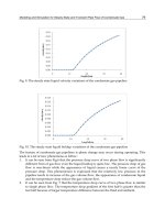
Figure 6.1 Corneal topography maps: post-photorefractive keratectomy for hypermetropia.
(a) Rings suggest the central cornea is regular. (b) Colour scale image of same eye shows treatment zone is
decentred by 1·3 mm.
50·00
49·00
48·00
47·00
46·00
45·00
44·00
43·00
42·00
41·00
40·00
39·00
38·00
37·00
36·00
35·00
34·00
33·00
32·00
31·00
REl 1 D
Axis Dist Pwr Rad Z
000 0·00 45·90 7·35 0·00
(a)
(b)
Box 6.2 Example of effective corneal
power calculation following refractive
surgery using the contact lens
method
• CL base curve is 40 D (use refractive index
1·3375 to convert a base curve from mm to
D if necessary)
• CL power is 0 D (plano)
• SE at comeal plane with CL is –4 D
• SE at comeal plane with CL is –2 D
• Then the average effective corneal power is
[40 + 0 + (–4) – (–2)] = 38 D
CL, contact lens; SE, spherical equivalent
camera linked to a computer enables the
reflected corneal rings to be simultaneously
sampled at several thousand points. Once
processed, these data provide a detailed three-
dimensional corneal shape map. Such corneal
mapping (Figure 6.1) is useful for measuring the
corneal curvature of eyes in which keratometry is
difficult, particularly those with irregular
astigmatism. The averaging of a large number of
data points makes topography more accurate
than keratometry in such situations, although
only the central readings should be used. A
study has shown that a corneal topography
system, an automated keratometer, and a hand-
held keratometer are as accurate as the “gold
standard” manual Javal-Schiotz keratometer.
12
If neither keratometry nor topography is
possible, then a best estimate of anterior corneal
curvature must be used. The options in these
circumstances are as follows:
• Directly view the cornea in profile and
estimate curvature
• Estimate curvature using ultrasound B-mode
images (see below) in two orthogonal planes
• Use measurements obtained from the fellow
eye
• Assume an average value (7·80 mm).
Axial length measurement
Axial length of the eye is measured from the
corneal vertex to the fovea. This visual axis
measurement is made using either A-mode
ultrasound, on occasions aided by B-mode
ultrasound, or an optical interferometric
technique.
A-mode ultrasound
Preparation
Anaesthetic drops are first instilled into the
eye. In infants or sensitive (non-pregnant)
adults, Proxymetacaine is the local anaesthetic
of choice because it does not sting. Alternatively,
Oxybuprocaine 0·4% may be used. The patient
is usually seated at a slit-lamp assembly with
their chin on a rest and their forehead against a
band. The ultrasound probe is commonly
housed in a spring-loaded assembly, such as a
tonometer (set at ≤10 mmHg). This avoids
indenting the globe on contact, a source of error
that produces a short axial length measurement.
If preferred, the ultrasound probe can be hand
held, and this is often useful if a patient has
restricted physical mobility. Not all hand-held
probes are housed in a spring-loaded sleeve and
care must be exercised to avoid globe indentation.
Ideally, the transducer contains a central light
on which the patient fixates and aids visual
axis alignment. The patient should be asked
specifically whether they can see the transducer
light; if they are unable to do so then it is vital to
encourage the fellow eye to fixate (see below).
As the probe is brought into direct contact with
the anaesthetised cornea, the patient is asked to
look into the centre of the transducer light and
the operator should use the corneal reflex of the
fixation light as an aid to alignment. The tear
film should provide sufficient “couplant” to
allow efficient transmission of ultrasound pulses
into the eye.
Technique
The A-mode transducer is commonly 5 mm
in diameter and emits short pulses of weakly
focused ultrasound with a nominal frequency of
10 MHz. In the intervals between these emissions,
echoes are received by the same transducer,
converted to electrical signals, and plotted as
spikes on a display. The height of a spike on the
y-axis indicates the amplitude of an echo. The
position of a spike along the x-axis of the display
is dependent upon the arrival time of an echo at
the transducer face (Figure 6.2). Most systems
presuppose a higher velocity of sound in the
cataractous lens than in the aqueous and vitreous
(which are assumed to have equal velocities).
Table 6.1 gives a list of some of the velocities
used in commercially available systems. Most use
CATARACT SURGERY
70
in-built pattern recognition criteria to determine
a “good” trace. Typically, these are three echoes,
greater than a predetermined amplitude, which
occur within ranges (or gates) predicted for the
anterior lens interface, posterior lens interface,
and vitreo–retinal interface. No system can
determine the origin of the echoes, and it is up to
the operator to determine whether the trace is
acceptable. It is therefore advantageous if the
system indicates which echoes have been selected
for a measurement.
Axial length measurement is given as a digital
read-out alongside the A-mode trace. The
accuracy to which systems will measure a
calibrated distance depends upon a number of
factors and is typically 0·03 mm (if full wave
rectification of the radiofrequency echo signal
should be used to produce the echo “spike” on
the display, and measurements taken on the
leading edge of the echo). The accuracy of
measurements from a skilled operator in a
regularly shaped eye is generally within 0·1 mm.
Visual axis A-mode traces are shown in
Figure 6.3a–f,h. The major source of error in
the measurement of axial length is due to
misalignment of the transducer with respect to
the eye. Misalignment errors can be extremely
large (Figure 6.3g) and typically overestimate
the axial length measurement.
Avoiding misalignment errors
Corneal illumination and pupil size The
eye should be illuminated and/or the room light
adjusted so that it can be seen clearly without
stray corneal reflections. If the eye is directly
illuminated, then care must be taken not to
bleach the patient’s retina and impair their
ability to fixate. Accurate alignment of the probe
with respect to the visual axis is easier with a
constricted pupil. However, if the selected
formula for lens implant power calculation
requires an anterior chamber depth, then it is
theoretically better to dilate the eye before
measurement. This prevents accommodation,
which may cause anterior chamber shallowing
and the lens thickness to increase. A 0·7 mm
increase in lens thickness during accommodation
has been reported,
13
but even in such an extreme
case the overall axial length measurement would
be increased by only 0·04 mm.
Echo appearance As previously mentioned,
A-mode axial length measurement depends on
the echo characteristics of three key interfaces.
The anterior lens interface arises after the
echolucent anterior chamber. The cataractous
lens is often echogenic but the posterior lens
interface is the last echo before the echolucent
vitreous cavity (although an artefactual echo, a
reflection from the internal lens, may be seen
after the posterior lens interface echo, or echoes
BIOMETRY AND LENS IMPLANT POWER CALCULATION
71
Transducer
Echo
amplitude
A-Scan display
Time of receiving echo
Sound
beam
Figure 6.2 A-mode ultrasound trace.
Table 6.1 Calibrated sound velocities in some
commercially available A-mode systems
Tissue/material Calibrated sound
velocity (m/s at 37°C)
Aqueous 1532
Vitreous 1532
Cataractous lens 1640
Intumescent cataract 1590
Phakic eye (mean velocity) 1550–1555
Aphakic eye (mean velocity) 1533
Pseudophakic eye (mean velocity) 1553
Lens implant PMMA 2381–2720
Lens implant silicone 980–1000
Note that some systems allow the user to input a specific
velocity. PMMA, polymethylmethacrylate.
CATARACT SURGERY
72
may arise from vitreous opacities). The next
echo is from the vitreo–retinal interface. If
the pulses of ultrasound strike the lens and
vitreo–retinal interfaces perpendicularly then the
echoes arising from those interfaces will be
higher in amplitude, more steeply rising from the
baseline, and shorter in duration (narrower).
These features are not observed if the transducer
is misaligned obliquely.
Eye fixation If the individual cannot see
the transducer fixation light then the fellow eye
should used to fixate on a separate target. In all
cases, the reflection of the transducer fixation
light on the cornea as it is placed on the eye,
and the position of the transducer tip, should
be observed carefully. The machine should be
positioned so that it is easy to observe the
display and the patient’s eye at the same time.
a)
0 10 20 30mm 0 10 20 30mm
0 10 20 30mm 0 10 20 30mm
0 10 20 30mm 0 10 15 30 40mm
0 10 20 30mm 0 10 20 30mm
c)
e)
g)
b)
d)
f)
h)
Figure 6.3 A-mode traces: cursors directly above horizontal axis indicate echoes accepted by machine in
measurement. (a) Nanophthalmic eye (visual axis). (b) Average length eye (visual axis). (c) Dense cataract with
multiple internal lens echoes (visual axis). (d) Highly myopic eye (visual axis). (e) Posterior staphyloma: note the
gradual slope of vitreo–retinal interface (visual axis). (f) Highly myopic eye with posterior staphyloma: note the
gradual slope of vitreo–retinal echo (visual axis). (g) Non-visual axis A-mode trace: system ignores vitreo–retinal
interface echo (arrow) as amplitude too low and accepts echo from a more posterior structure; measurement
1·4 mm too long. (h) Same eye as (g) but with visual axis alignment.
BIOMETRY AND LENS IMPLANT POWER CALCULATION
73
Gain control To confirm the acquisition of
a “good” A-mode trace, the gain (or sensitivity)
setting should be varied to alter the echo
amplification. The gain should be increased to
check whether an echo is present before the
presumed vitreo–retinal interface echo. If an
Figure 6.4 B-mode sections (for right eyes the temporal globe is on the left side of the image and for left eyes
on the right side of the image). (a) Long eye (25·9 mm): foveal dip (arrow). (b) Very long eye (36·8 mm):
massive posterior pole staphyloma. (c) Silicone oil filled vitreous cavity: eye measures 49 mm on B-scan, but
actual axial length is 34·3 mm. (d) Long eye (26·0 mm): posterior staphyloma centred nasal to disc.
(e) Buphthalmic globe: very long eye (37·5 mm): deep anterior chamber. (f) Megalocornea: average length eye
(23·1 mm): deep anterior chamber (5·2 mm).
a)
b) c)
d)
e) f)
CATARACT SURGERY
74
echo does appear then the transducer alignment
is probably poor (Figure 6.3g). Should ultrasonic
pulses strike the vitreo–retinal interface very
obliquely and the gain is set to a low value, then
the interface echo may not be displayed. The
instrument then measures from the anterior
cornea to a structure beyond the vitreo–retinal
interface. This trace appearance also occurs in
eyes with a dense nuclear cataract, in which an
internal lens echo is mistaken by the instrument
for the posterior lens interface.
The gain should be reduced to prevent echo
saturation. Echo saturation is seen as flattening
at the top of the amplitude spikes when the
display maximum is reached on the y-axis scale.
These amplitudes cannot be compared because
they all appear to be the same height.
Ultrasound B-mode
This technique uses pulses of ultrasound to
produce cross-sectional images of the globe.
Patients are usually examined seated. The probe
is smeared with a coupling gel and placed
horizontally on the centre of the closed upper
eyelid. Pulses of sound are sent from the
transducer probe, through the eyelid, and into
the eye. Echoes from the ocular structures are
0 10 15 30 40mm 0 10 20 30mm
0 10 20 30mm0 10 20 30mm
0 10 0 10 15 30 40mm20 30mm
a) b)
c) d)
e) f)
Figure 6.5 A-mode traces. (a) Aphakic, myopic eye. (b) Anterior chamber polymethylmethacrylate (PMMA)
implant in situ: note the multiple reflection echoes from implant displayed in vitreous cavity. (c) Posterior
chamber PMMA implant in situ: multiple reflections from implants displayed in vitreous cavity; machine accepts
multiple reflection as the vitreo–retinal interface and measures globe inaccurately as 15·3 mm. (d) Same eye as
(c): manual gates used to indicate to system which echo to accept; correct axial length 25·0 mm. (e) Silicone
implant in situ (thickness 1·4 mm). (f) Silicone oil filled vitreous cavity: low amplitude echo from vitreo–retinal
interface and multiple reflection artefact at approximately 12·0–15·0 mm, which the system may mistake for the
vitreo–retinal interface; system measures axial length as 41·2 mm using manual gates (corrected axial length
29·4 mm, obtained by scaling vitreal length by × 0·64).
BIOMETRY AND LENS IMPLANT POWER CALCULATION
75
received by the same transducer and plotted as
brightness modulated spots on the display. A
bright spot indicates a high amplitude echo and
a dim spot a low amplitude echo.
The images shown here were taken using a
Sequoia 512 whole body scanner (Acuson). The
probe consists of an array of 128 transducer
elements, which are fired electronically in
overlapping batches to simulate a single moving
transducer. For each probe position, a cross-
sectional B-mode image is produced and refreshed
at a rate of 25 B Scans per second, so that any
eye movement is clearly resolved on the image.
Positional and angular adjustment of the probe
allows the central horizontal section of the globe
to be displayed. Figure 6.4 shows B Scans taken
on eyes of various dimensions. Appearing
echolucent internally, the anterior and posterior
surfaces of the cornea are clearly resolved. With
less sophisticated scanners, 3 mm thick solid gel
pads can be used as a “stand-off” to improve
resolution of the anterior chamber. It is sometimes
possible to see the foveal dip (Figure 6.4a) and
posterior staphyloma are easily imaged. In patients
with poor fixation or a posterior staphyloma,
B-mode measurement of vitreal length is likely
to be considerably more accurate than A-mode.
In contrast, aphakic eyes (Figure 6.5a) are
generally easy to measure using A-mode
examination because there is no attenuation of
the sound by the lens.
Complex and difficult axial length
measurements
Dense cataracts
A dense cataract can attenuate sound pulses
strongly and reduce the amplitude from the
vitreo–retinal interface echoes. Alignment is
more difficult if the patient is unable to fixate and
the corneal reflex of the transducer light is more
difficult to see on the background of a white or
brown cataract. In these circumstances it may be
worthwhile crosschecking measurements using
the B-mode technique.
Posterior staphyloma/irregularity
of eye shape
Myopic eyes may be difficult to measure in the
presence of a posterior pole staphyloma. In such
cases the foveal interface presents obliquely to the
incoming pulses of ultrasound and the criteria of a
steeply rising vitreo–retinal interface echo is not
met (Figure 6.3e,f). It is worthwhile crosschecking
measurements in such eyes using the B-mode
technique or by optical interferometry.
Vitreal echoes
Vitreal echoes arise in pseudophakic eyes
from multiple reflections between the implant
and the transducer face (Figure 6.5b–d).
Vitreous opacities such as asteroid hyalosis also
generate high amplitude echoes. Such echoes
may be accepted by the A-mode system as the
vitreo–retinal interface (Figure 6.5c). If so,
manual gate selection should be used to aid the
machine in locating the true vitreo–retinal
interface echo.
The B-mode appearances of the
pseudophakic eye (implanted with one IOL) are
shown in Figures 6.6 and 6.7a. It is possible to
distinguish the material from which an implant
is made and to estimate lens implant power
using B mode. Most implants are made from
PMMA, acrylic, or silicone. Of these materials
PMMA scatters ultrasound waves the most, and
silicone does so the least. Thus, PMMA
generates the highest amplitude echoes from the
implant surfaces and appears brightest on B
mode, producing stronger multiple reflections.
The refractive index of PMMA is highest (1·49)
and that of silicone is lowest (1·41). PMMA lens
implants therefore appear much thinner than do
silicone implants of the same power (for
example, a 18 D PMMA implant measures
0·90 mm centrally).
Silicone oil/heavy liquid in vitreous
The presence of silicone oil or heavy liquid in
the vitreous has a dramatic affect on the
appearance of both the A-mode trace (Figure 6.5f)
and the B-mode (Figure 6.4c) image. The
velocity of ultrasound in these liquids is very low
in comparison with that in biological tissues (for
example, velocity in 1000 cS silicone oil is
982 m/s). Because the A-mode system assumes
a velocity of 1532 m/s in the vitreous and the
B-mode system assumes an average velocity in
tissue of either 1540 m/s or 1550 m/s, the
imaged eye may appear considerably elongated
(Figures 6.4c and 6.5f). To determine the actual
vitreal length, the measured vitreal length should
be multiplied by the ratio of the sound velocity
in silicone oil to that in vitreous (a factor of
0·64). Further confusion occurs because the
acoustic properties of silicone oil and heavy
liquid differ so much from vitreous that the echo
from the posterior lens interface is increased and
multiple reflections commonly occur. This may
cause a high amplitude echo at twice the
expected distance from the transducer face,
typically arising at around 12–15 mm (Figure
6·5f), which then fools the instrument (and
some examiners) to record that the eye is very
short. Oil also attenuates the sound strongly,
resulting in a reduction in amplitude of the echo
CATARACT SURGERY
76
Figure 6.6 Transverse B-mode images: pseudophakic eyes. (a) Anterior chamber polymethylmethacrylate
(PMMA) implant in situ. (b) Posterior chamber PMMA implant in situ. (c) Posterior chamber Acrysoft
TM
implant in situ. (d) Posterior chamber 21D silicone implant plate haptic (C11UB; Bausch and Lomb) in situ
(measures 2·2 mm thick on B-scan scale; 1·4 mm when corrected for velocity in silicone as compared with
system velocity of B-scanner).
a)
b)
c)
d)
from the vitreo–retinal interface (Figure 6.4c
and 6.5f).
Usually, silicone oil is removed at the time of
lens implantation, but if oil is to be retained it
has been recommended that convex–plano
(plano posterior) implants be used.
13
Silicone
lens implants should not be used in conjunction
with silicone oil (see Chapter 7). If biconvex
lenses are used then the loss of refracting power
of the implant in oil has been calculated as
67·4/r, where r is the back radius of the IOL in
millimetres.
14
This is negative for a biconvex lens
and positive for a meniscus lens. In contrast, for
a convex–plano implant r is infinity and 67·4/r is
therefore equal to 0. It has also been suggested
that the IOL power should be calculated to allow
for the refractive index of silicone oil (1·4034).
This requires the addition of a constant that is
dependent on the axial length of the eye and is
calculated as 67·4/[(0·708 × Axial length in
BIOMETRY AND LENS IMPLANT POWER CALCULATION
77
Figure 6.7 Transverse B-mode images: pseudophakic eyes (unusual situations). (a) Anterior globe: posterior
chamber polymethylmethacrylate (PMMA) negative power implant (minus 3 D) in situ; note the multiple
reflections from implant displayed in vitreous. (b) Anterior globe: anterior chamber PMMA implant (short
arrow) and posterior chamber PMMA implant long arrow) in situ. (c) Anterior globe: two silicone “piggy back”
implants in bag; anterior implant is of lower power (10 D) and therefore thinner than the posteriorly positioned
implant (26 D). (d) Nanophthalmic eye (15·6 mm): three PMMA “piggyback” implants in the bag; note that
attenuation of sound by implants gives rise to shadowing in the orbital fat pad.
a)
b)
c)
d)