Deterministic Methods in Systems Hydrology - Chapter 2 ppt
Bạn đang xem bản rút gọn của tài liệu. Xem và tải ngay bản đầy đủ của tài liệu tại đây (1.57 MB, 16 trang )
- 24 -
Water storage and
water movement
Rapid response
CHAPTER 2
Nature of Hydrological Systems
2.1 THE HYDROLOGICAL CYCLE AS A SYSTEM
The hydrological cycle is usually depicted in a form similar to that shown in Figure
2.1, which is taken from a classical reference work by Ackerman et al. (1955). An alternative
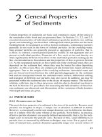
representation, which is more suitable for the present discussion, is shown in Figure 2.2. In the
latter figure the rectangles denote various forms of water storage: in the atmosphere, on the
surface of the ground, in the unsaturated soil moisture zone, in the groundwater reservoir below
the water table, or in the channel network draining the catchment. The arrows in the diagram
denote the various hydrological processes responsible for the transfer of water from one form of
storage to another.
A study of Figure 2.2 reveals the relationship between the various forms of water
storage and water movement. Thus the precipitable water ( W) in the atmosphere may be
transformed by
precipitation (P)
to water stored on the surface of the ground. In the reverse
direction, water may be transferred from the surface of the bare ground or from vegetation to the
atmosphere by the processes of evaporation and transpiration (E, T).
Some of the water on the surface of the ground will infiltrate the soil through its surface
(F)
while some of it may find its way as
overland flow (Q
0
)
into the channel network. During and
following precipitation, soil moisture in the unsaturated sub-surface zone is replenished by
infiltration (F)
through the surface. If the field
moisture deficiency
of the soil, due to evaporation,
transpiration and drainage since the previous precipitation event, is substantially satisfied by
the current event, there will be a
recharge (R)
to groundwater, and also a certain amount of
interflow
(Q
i
)
or
lateral flow
through the soil, which is intercepted by the channel network.
The groundwater storage is depleted by groundwater outflow (Q
g
), which enters the
channel network and supplies the streamflow during dry periods. During prolonged drought,
soil moisture may be replenished through
capillary rise (C)
from groundwater. Overland flow
(Q
0
),
inter-flow (a) and groundwater flow (Q
g
)
are all combined and modified in the channel
network to form
the runoff (R
0
)
from the catchment. These various hydrological processes are
discussed in detail in textbooks and monographs on physical hydrology (e.g. Eagleson,
1969; Bras, 1990) and are dealt with here in subsequent chapters.
It is not easy in practice to distinguish from a record of runoff, the separate components
of overland flow, interflow and groundwater flow discussed above. In the case of experimental
plots, or of short-term event investigations, techniques using chemical or radioactive tracers
can he used. However, these methods are not suitable for long-term routine monitoring of large
catchments. The most that can be done is to distinguish between the relatively rapid
response of the catchment to a precipitation event and a second slower response. The quick
response is often identified with surface runoff in the form of overland flow and interflow in the
upper layers of the soil, and the slower response with the passage of the water through both
the unsaturated and saturated soil moisture zones. Accordingly, most models of catchment
behaviour used in applied hydrology are elaborations of the simplified catchment model
shown in Figure 2.3. In this figure, the total response of the catchment to precipitation is due
to three sub-systems: one representing direct storm response, the second representing
- 25 -
Threshold effect
groundwater storage and outflow, and the third representing the unsaturated soil moisture
zone.
It would be desirable to model the overall catchment response shown in Figure 2.3 by a
linear model. However, it is generally considered that recharge to groundwater (R) only takes
place to an appreciable extent after the field moisture deficiency has been satisfied. This
- 26 -
introduces into the catchment response a threshold e
f
fect. Since such an effect is essentially
non-linear, it is not possible to model the total catchment response with a linear model without
incorporating such a feature. Accordingly, it is not surprising that the first attempts at rainfall-
runoff modelling concentrated on the direct storm response, where there is no such initial
hindrance to the use of a linear model. As will be shown below, the unit hydrograph
approach introduced by Sherman ( 1932a) is based essentially on the assumption that the
catchment converts effective rainfall to storm runoff in a linear time-invariant fashion. The unit
hydrograph approach was used widely in applied flood hydrology for at least 25 years before
its relationship to linear systems theory was realised and taken advantage of.
Black box Conceptual
models
Continuum
mechanics
Linear time-invariant X X
Linear time-variant X X
Non-linear tim e-variant
If the recharge to the groundwater sub-system is known, then there is no reason why this
component should not be treated in a similar fashion. However, it was also relatively late when
Kraijenhoff van de Leur (1958, 1966) did this. Because the techniques were developed firstly in regard to
the component of direct storm response, there will be a tendency in this book to cite examples from this
area. But it should be realised that all of these techniques are equally applicable to groundwater flow.
Mention was made in Chapter 1 of the three distinct approaches to the analysis of systems:
black-box analysis,
conceptual models,
equations of continuum mechanics.
Any one of these approaches can be applied to each of the components of the total
catchment response shown in Figure 2.3. In each approach one may assume the sub-system to
be linear or non-linear, and to he time-invariant or time-variant. Without further classification, this divides
possible models of independent components of the catchment response; or individual hydrological
processes, into twelve classes as indicated in Figure 2.4. In the present book it is not possible to
deal with all or even with a majority of these classes. Accordingly attention will be concentrated on
- 27 -
Unit hydrograph
Basic propositions
linear time-invariant black-box analysis, linear conceptual models and non-linear conceptual
models, i.e. on the upper left-hand corner of the matrix shown in Figure 2.4.
The remainder of the present chapter will be devoted to a review of classical unit hydrograph
theory and of the early classical methods for the identification and simulation of hydrological
systems. The following cam
-
ter is devoted to a discussion of some of the mathematical tools require
d
for understanding the deterministic methods used in systems hydrology.
2.2. UNIT HYDROGRAPH METHODS
The unit hydrograph concept and its development were one of the,
highlights of the classical period of scientific hydrology. Though unit hydrograph
methods are dealt with elsewhere in this book, the approach is briefly reviewed
here so that the black-box approach to hydrological systems can be placed in its proper
historical context.
Figure 2.5 is a reproduction of Figure 1 of the basic paper by Sherman (1932a), which
introduced the concept of the unit hydrograph. In this figure a triangular form of hydrograph
is assumed to represent the direct storm runoff due to effective rain falling continuously and
uniformly for the unit interval. The figure shows how superposition may be used to build up the
runoff of periods of uniform rainfall equal to twice the unit period, three times the unit period,
etc. It will be noted that, if the duration of this continuous effective precipitation is greater than
the base of the unit hydrograph, the runoff becomes constant.
As mentioned above, the unit hydrograph methods were widely used in applied
hydrology for about 25 years without recognition of the essential assumption involved, namely
that of a linear time-invariant system.
The classical unit hydrograph approach is described in a number of textbooks published at
the end of the 1940s. The book by Johnstone and Cross (1949) contains a particularly good
discussion from this classical period. In it they state the basic propositions of the unit
hydrograph approach as follows:
"We are now in a position the three basic propositions of unit graph theory, all of which refer
solely to the surface-runoff hydrograph:
- 28 -
S
-
hydrograph
Instantaneous unit
hydrograph (IUH)
I. For a given drainage basin, the duration of surface runoff is essentially constant for
all uniform-intensity storms of the same length, regardless of differences in the total volume of
the surface runoff.
II. For a given drainage basin, if two uniform-intensity storms of the same length produce
different total volumes of surface runoff, then the rate of surface runoff at corresponding
times t, after the beginning of the two storms are in the same proportion to each other,
as the total volumes of the surface runoff.
III. Time distribution of surface runoff from a given period is independent of
concurrent runoff from antecedent storm periods."
Johnstone and Cross make the following comment:
"All these propositions are empirical. It is not possible to prove them mathematically. In fact, it is
a rather simple matter to demonstrate by rational hydraulic analysis that not a single one of
them is mathematically accurate. Fortunately, nature is not aware of this."
In the twenty years after Sherman's basic paper of 1932 the unit hydrograph approach
developed into a flexible and useful tool in applied hydrology and only later was a full theory of
the unit hydrograph developed.
The original unit hydrograph developed by Sherman was a continuous runoff hydrograph
due to uniform rainfall in a unit period. A later advance in classical unit hydrograph theory was
the discovery by W. Langbein that the S-hydrograph or S-curve could be used to convert a unit
hydrograph from one duration to another. Before this, it was necessary to find a storm of the
appropriate duration in the period of record in order to derive the required unit hydrograph from
the data.
The S-hydrograph or 5-curve is defined as the hydrograph of surface runoff produced by
continuous effective rainfall at a constant rate. Figure 2.5 (taken from Sherman's original paper)
shows the manner in which the S-hydrograph can be built up from the unit hydrograph for the
particular shape of a triangular unit hydrograph. Using a common tune axis, the corresponding
blocks of rain are frequently plotted upside down above the hydrograph. These are not shown
in Figure 2.5.
Once the S-hydrograph has been adequately defined on the basis of a given unit
hydrograph of any specified unit period. a unit hydrograph of a new unit period (D) can be
derived from it. We simply displace the S-hydrograph by the amount D, subtract the
ordinates of the two S-hydrographs, and normalise the volume by dividing by D. This process
can be represented by the equation
( ) ( )
( )
D
S t S t D
h t
D
(2.1)
As D becomes smaller and smaller the process represented by equation
(2.1) approaches closer and closer to the definition of differentiation and in the limit we have
( ) ( )
( )
D
S t S t D
h t
D
(2.2)
The hydrograph defined by equation (2.2) is known as the instantaneous unit
hydrograph (IUH).
- 29 -
Storm event
The first step in analysing an actual hydrograph is to separate the baseflow from the
direct storm runoff and to reduce the total precipitation to effective precipitation.
Hydrological literature abounds in methods for making this separation. The effect of
contrasting types of storm event on the runoff hydrograph is shown schematically in
Figure 2.6 due to Horton (1935).
Figure 2.6A shows the effect of a storm event with very high intensity of rainfall and
very short duration. Because of the very high intensity of rainfall, surface runoff would
occur due to the exceedance of the limiting or maximum rate of infiltration. But due to
the very short duration, and consequently the very small volume of infiltration, it is
unlikely that the field moisture deficit would be satisfied. Hence, there would be no
recharge to groundwater. Under these conditions, the baseflow recession before and
after the storm event would follow the same general curve, and the response of the
hydrograph would consist of a sharp rise and sharp recession back to the same master
curve of baseflow recession.
If on the other hand the storm event consisted of very prolonged rainfall of very
small intensity, we would get the condition represented schematically in Figure 2.6B. In this
case the intensity does not exceed the maximum infiltration rate and thus there is no
surface runoff. However, the rainfall is sufficiently prolonged to make up the field
moisture deficiency and to give a recharge to groundwater storage. The effect of this
recharge is to increase the amount of groundwater outflow, or baseflow, and the
recession curve will be shifted as shown in stylised fashion in Figure 2.6B. In the latter
case, the recession curve after the storm event has the same shape as before, but is
shifted in time.
More usually, the storms which are of consequence in hydrological analysis, are
intermediate between the two extreme forms discussed above. Both effects are combined
so that we get, on the one hand, a distinct peakflow and a measurable amount of surface
runoff, and on the other hand, a recharge of groundwater, giving a shift in the master
recession curve. This mixed condition is shown schematically in Figure 2.6C. One of the
first steps necessary in unit hydrograph analysis is to separate out these two effects.
In practice, the applied hydrologist usually separates the baseflow in some arbitrary
fashion, and then adjusts the total precipitation so that the volume of effective precipitation is
equal to the volume of direct storm runoff. No attempt is made to link infiltrating
precipitation with groundwater recharge and hence with ground-water outflow.
- 30 -
Infiltration capacity
curve
W
-
index method
-index method
Linearity and
time-invariance
Separation of
baseflow
Effective
precipitation
The reduction of total precipitation to effective precipitation is also frequently made in
an arbitrary manner. Figure 2.7 shows three approaches to the adjustment of the precipitation
pattern.
In the first method, an
infiltration capacity curve,
which decreases
as curve
the soil
moisture is satisfied, is estimated, and an allowance is also made for the retention of
precipitation on vegetation and on the surface of the ground without the occurrence of
runoff.
In
the second method (which is called the
W-index method),
the difficulty of estimating the
variable infiltration capacity is avoided, by taking it to be a constant value which will make the volume
or effective precipitation equal to the volume of direct storm runoff after allowance for retention.
In the third method (known as the
-index method)
no allowance is made for retention and
we simply seek the value of infiltration capacity such that the volume of precipitation in
excess of it, is equal to the volume of surface runoff. It is clear that the use of either of
the latter two methods, or the incorrect use of the first method, would result in the derivation of an
erroneous unit hydrograph, even if the total precipitation and total rung were measured without
error and the catchment truly acted in a linear and time-invariant fashion.
All of the concepts and methods of the classical unit hydrograph approach can be neatly
formulated in systems nomenclature. The only necessary assumptions of the unit hydrograph
approach are those of linearity and time-invariance (Dodge, 1959). In the classical statement of
unit hydrograph principles by Johnstone and Cross (1949) as quoted above in Section 2.3, the
basic propositions involve both these two concepts.
Proposition I invokes time-invariance when it compares storms occurring at different times
and invokes linearity when it assumes the base length of the unit hydrograph to be constant.
Proposition II again invokes time-invariance by comparing two storms and invokes linearity in
assuming proportionality of the runoff ordinates. Proposition III is an alternative statement of the principle
of superposition i.e. of linearity applied to two successive storms.
The above considerations show that linearity and time-invariance are necessary for the basic
propositions given by Johnstone and Cross. A comparison indicates that the two assumptions
of linearity and time-invariance are also sufficient for the three basic propositions.
The unit hydrograph for a unit duration (D = I) is clearly the pulse response for that duration and
the instantaneous unit hydrograph is the impulse response of the catchment. The S-hydrograph
corresponds to the step-function response of system theory.
The problems of the separation of baseflow and the determination of effective
precipitation is a reflection of the fact that the direct storm response is merely one
component of the total catchment response as shown above in Figure 2.3. The systems
approach, however, emphasises the undesirability of a partial approach. The failure to link
the portion of the precipitation, which infiltrates, with the groundwater recharge, may give
results, which are not only inaccurate, but also grossly inconsistent and erroneous.
Once the problem has been formulated in systems terms, it is clear that the problem
of deriving a unit hydrograph is one of solving an integral equation (1.15) in the
continuous case and solving a set of simultaneous linear equations (1.20) in the discrete
case. There have been a number of attempts to estimate simultaneously the unit hydrograph
itself and one or other of the "slow response" components. In the case of the effective precipitation
function, see for example, the CLS method used by Todini and Wallis (1977), and the
- 31 -
iterative solution of problems of identification and detection, presented by Sempere Torres,
Rodriguez and Obled (1992 ).
2.3 IDENTIFICATION OF HYDROLOGICAL SYSTEMS
In the classical unit hydrograph approach it was found necessary to devise methods
for the derivation of a unit hydrograph by the analysis of complex storms in which the rate of
effective precipitation was not uniform throughout the storm. In the early studies the procedure
used was essentially one of
trial and error.
In this method, which is shown schematically in Figure
- 32 -
Iterative method
Forward substitution
Method
of least
squares
2.8, a shape of unit hydrograph was assumed and applied to the effective precipitation in
order to produce an estimate of the runoff. This was then compared with the recorded runoff. If the
fit was felt to be adequate, the shape of the unit hydrograph was adopted. But if not, it Was
modified until satisfactory agreement was obtained.
In 1939, Collins suggested an
iterative method.
A trial unit hydrograph, generated by
applying the assumed unit hydrograph to all periods of rainfall except the maximum, was
subtracted from the total measured hydrograph to give a net runoff hydrograph, which could be
taken as the runoff due to the maximum rainfall in a unit period. This net hydrograph when
divided by the volume of the maximum unit period rainfall, gave a second approximation
to the shape of the finite period unit hydrograph. The process was repeated until there was a
satisfactory correspondence between the shapes of unit hydrograph obtained on the two
successive iterations.
In the 1940s the derivation of the unit hydrograph from complex storms was
frequently based on the solution of the set of simultaneous equations giving the relationship
between sampled ordinates of the output and the ordinates of the finite period of the unit
hydrograph and the rainfall volumes in each unit period (Linsley, Kohler and Paulhus, 1949, pp.
444 - 449). These were of course the set of equations represented in matrix form by equation
(1.20) above.
When written out explicitly they have the form
y
0
= x
0
h
0
(2.3a)
y
1
= x
1
h
0
+ x
0
h
1
(2.3b)
y
2
= x
2
h
0
+ x
1 -1
h
1
+ x
0
h
2
(2.3c)
and so on. Note the change in notation compared with (1.19b). Subscripts are used instead of
arguments and lower case x denotes successive input volumes in this chapter.
The general form of the equation is
y
i
= x
i
h
0
+ x
i -1
h
1
+ x
0
h
i
(2.3d)
and the number of terms on the right hand side of the equation increase until it is equal to
either the number of elements in the input vector
(m + 1)
or the number of elements in the
pulse response vector (n + 1), whichever is the lesser. For the case of m < n, this equation is
given by
- 33 -
Simulation
Direct approach to
simulation
Transform methods
Optimisation methods
Regression models
y
m
= x
m
h
0
+ x
m -1
h
1
+ … + x
0
h
m
(2.3e)
and the next equation will be the same length, since x
m+1
= 0 and does not
contribute to it, thus giving
y
m +1
= x
m
h
1
+ … + x
0
h
m +1
(2.3e’)
The equations will remain the same length until i =
n,
after which
h
i
=
0 and each
successive equation will contain one less term
y
n
= x
m
h
n -m
+ … + x
0
h
n
(2.3f)
y
n+ 1
= x
m
h
n+ 1-m
+ … + x
1
h
n
(2.3f’)
The equations continue to decrease until ultimately we get
y
p
= x
m
h
p-m
= x
m
h
n
(2.3g)
Which is the last equation of the set
It would appear that the solution of the above equations is trivial since we can
proceed by forward substitution. In forward substitution, h
0
is the only unknown in equation
(2.3.) and hence can be determined from the values of y
0
and x
0
. Equation (2.3b) can then be
solved for h
1
using the known values of x
0
, x
1
and y
1
and the value of h
0
derived from
equation (2.3a). In practice, the existence of errors in the values of the effective
precipitation x(sD) or the direct runoff y(sD) will produce errors in the ordinates of the unit
hydrograph. Applied hydrologists knew that for certain patterns of effective precipitation. these
errors could build up rapidly and produce unreasonable results.
One method proposed to overcome this disadvantage was the solution of the equations
represented by equation (2.3) by the method of least squares. This method of unit
hydrograph derivation will be discussed in greater detail in Chapter 4. Barnes (1959)
removed any oscillations occurring in the unit hydrograph by deriving it in the reverse order i.e.
by backward substitution. This is in line with general experience in numerical methods where a
calculation, which is unstable in one direction, is usually stable if taken in the reverse direction.
Barnes further suggested that the estimated effective precipitation should be adjusted until the unit
hydrograph obtained in the forward and reverse directions was substantially the same. Later
attempts at developing objective and dependable methods of unit hydrograph derivation,
involving the use of transform methods or of optimisation methods both unconstrained and
constrained, will be discussed later in Chapter 4.
Although the derivation of the unit hydrograph from the outflow hydro-graph due to a
complex storm (which is the problem of identification) is a difficult one to solve, the
prediction of the flow hydrograph due to a complex storm, when the unit hydrograph is
known, is relatively easy. All that is required is the application of each of the volumes of
effective precipitation in a unit period to the known finite period hydrograph. To obtain the outflow
hydrograph each volume of effective precipitation must be carefully located in time and the
results summed to give the total outflow. In terms of the set of simultaneous equations
given by equation (2.3a) to (2.3g), the problem is one of determining the left hand side of the
equations knowing all the values of x
and all the values of h , which appear on the right hand
sides of the equations.
2.4 SIMULATION OF HYDROLOGICAL SYSTEMS
Even if we could solve the problem of identification completely, this would only
enable us to predict the future output from the particular system for which the
- 34 -
Synthetic unit
hydrographs
identification was made. Complete and accurate identification would not help us in any
way to predict the output from a similar system, far which records of input and output
were not available, or to study the effects of variations in the parameters due to natural
causes or human activity.
Furthermore, the black-box analysis of non-linear systems is
extremely difficult and there is still no adequate theory to deal with the analysis of
systems containing thresholds. Consequently, in order to predict the total catchment
response, and, in some cases, the response of catchment components, it is necessary
to turn to simulation as the basis of prediction. It is important to remember that in these
cases, we are still interested in the overall performance of the system rather than the
details. When we seek a model to simulate the system operation, we are still looking for
a reliable predictor, rather than a fundamental explanation, or a detailed reproduction of
the system
.
There are of course many methods of simulation. On the one hand we have direct
methods of simulation, which relate to a particular hydrological system. These include
the use of physical models in hydrology and the use of special purpose analogs. The
discussion of this direct approach to simulation is outside the scope of the present
chapter. In contrast to direct simulation, are the formulation of a mathematical model and
the solution of this model either by hand calculation, use of a desk calculator, or digital
computer. In this book, we are concerned only with the mathematical modelling of a
deterministic relationship between input and output variables.
Regression models have been widely used in applied hydrology down through the
years. The value of regression models is clearly their ability to predict, rather than the
investigation of the details of hydrological processes. A typical example of a regression
model is shown on Figure 2.9 (Benson, 1962). In this particular regression model, a
relationship is sought between the annual peak discharge for a recurrence interval of T
years (Q
T
) as the dependent variable, and a number of catchment parameters as
independent variables. In the case shown, the catchment parameters are:
the catchment area (A), the main channel slope (S), a measure of the surface storage
area (S
t
). the 24-hour rainfall for a recurrence period of T years (I), a measure of
freezing conditions in mid winter (t), and an orographical factor (0).
In Figure 2.9 the particular regression model is shown in three forms:
(1) as an indeterminate relationship between the dependent variable and the
independent variables;
(2) as an equivalent flow diagram, indicating that each of the independent variables can
be considered as input factors, which are raised to a particular power and then
multiplied together, to give the required output: and
(3) as a regression model, expressed as a relationship between the logarithm of the
dependent variable, and the logarithms of the independent variables. In this way the
relationship is transformed, so as to be linear in the unknown parameters, which can therefore be
found by linear regression analysis.
- 35 -
Multivariate analysis
100 200
actualroutingAon
-
30 day API
cRi
0 0
v i • N
Linear reservoir
St.
Venant equations
Even when the unit hydrograph approach is used it is necessary to establish
a regression model relating the unit hydrograph parameters to catchment characteristics. Synthetic
unit hydrographs are required for catchments with no flow records, and are formulated on
the basis of catchments in the same region for which records are available. Regression
models are also useful for investigating the variation of unit hydrograph characteristics with effects
of human activity, such as changes in agricultural practice or urbanisation.
Multiple regression analysis makes the assumption that all the errors are concentrated in the
dependent variable and also that the so-called independent variables are not correlated with one
another. Violation of the latter assumption does not prevent the derivation of a regression relationship,
which can be used as a prediction tool, but it renders meaningless the tests of significance used in a
regression analysis. In hydrology, due to the operation of geomorphologic factors, the
catchment parameters are often very highly correlated among themselves. Methods of
multivariate analysis seek to avoid the above problems by treating all the variables alike and
performing component analysis to determine if there are truly independent groupings of
variables.
The graphical method of coaxial correlation was widely used in the past in applied
hydrology (Linsley, Kohler and Paulhus, 1949, pp. 419- 424). It is essentially a graphical
method of non-linear regression and is suitable for the solution of ad hoc problems. One
of the disadvantages of coaxial correlation is the subjectivity involved. Becker (1966) has
indicated how the subjectivity can be substantially reduced by relating the shape of the
curves in the coaxial correlation diagram to given conceptual model of catchment behaviour.
Figure 2.10 is an example of a coaxial correlation diagram based on Becker's work which relates
potential catchment recharge to initial moisture content, time of year, duration and amount of
rainfall.
In order to build up a model of total catchment response, it is necessary to model
separately the components of this response. As indicated earlier, this may be done either by
black-box analysis, by the use of simple conceptual models, or by solution of the equations of
continuum mechanics. In this book, only black-box analysis and simple conceptual models will be
considered. It was noted above that the unit hydrograph method had been used widely in applied
hydrology, long before the development of a theory of black-box analysis of hydrological system.
Similarly, simple conceptual models were devised for use in applied hydrology long before system
simulation was applied to hydrology in a systematic fashion.
- 36 -
A good example of this, is the well-known Muskingum method of flood routing. This
method assumes that the storage in a river reach can be represented by
S(t) = K[xI(t) + (1 – x)Q(t)] (2.4)
where S(t) is the storage, I(t) is the inflow at the upstream end of the reach. Q(t) is the
outflow at the downstream end of the reach, and x and K are parameters to be determined. For
the particular case of x = 0 equation (2.4) reduces to the equation for a linear reservoir, which
is widely used as a basis for building simple conceptual models. It will figure prominently in
later chapters.
In classical hydrology, the Muskingum parameters were determined as follows. From
the record of I and Q for an existing flood, the value of the storage S(t) in the reach is
obtained from the hydrological continuity equation
[ ( ) ( ) ( )
d
S t I t Q t
dt
(2.5)
- 37 -
Muskingum method
of flood routing
Parameter
identification
Reservoir storage
Wedge storage
Total catchment
response
by the following empirical procedure.
Various values of x between 0 and 0.5 were selected and the weighted flow in the reach
– i.e. the quantity within square brackets in equation (2.4)- calculated and plotted against
the storage. The value of x selected. was the value which gave the least dispersion about
a straight line in a graphical plot of storage against weighted flow. A line was drawn through the
plotted points for this particular value of x. The slope of this line determines the value of the
parameter K, and it has the dimension of time. The values of x and K thus found were used
to determine the outflow from the reach for a new design inflow I.
It may be instructive to reinterpret the above procedures in terms of systems nomenclature.
The Muskingum method is clearly a method of simulation based on a simple conceptual
model, rather than the solution of the St. Venant equations for unsteady flow in an open
channel. For the case of a natural reach of a river, the solution of the latter equation is
difficult, even with the aid of a digital computer. It is interesting to note that, even if the
equations can be satisfactorily solved on a computer. it is necessary to use an existing record
of water level at two points, which may be converted to flow, in order to determine reliable
values of the "friction factor to be used.
The graphical procedure for the determination of x and K in the classical Muskingum
method is essentially a method of identifying the values of the parameters of the Muskingum
- 38 -
model for the special case tinder consideration. It constitutes therefore parameter identification
for the chosen conceptual model. The use of the model and these values of the parame
ters
, to
estimate the design outflow for a design inflow, represent the relatively simple problem
of prediction using the derived river reach response. The form of equation (2.4) was based
on heuristic assumptions about relative importance of reservoir storage and wedge storage in
the reach. In the systems approach no use would be made of such physical assumptions
,
instead, equation (2.4) would be interpreted as an assumption that the storage in the reach is
a linear function of the inflow and the outflow.
The behaviour of this linear model can then be characterised by its impulse
response function. The impulse response of the Muskingum model is a linear
combination of a negative delta function at the origin and a negative exponential function
of time. Under certain conditions, the negative delta-function can produce negative
outflows from the reach. This is a significant weakness in this popular model.
Figure 2.11 shows an outline flow diagram for the older Stanford Mark IV model for
simulating an entire catchment (Crawford and Linsley, 1966). This is not a complete
description of the model and needs to be supplemented by a series of instructions
indicating how water is to be transferred from one element of the model to another.
- 39 -
Total catchment
response
An alternative way of representing such a conceptual model is shown in Figure 2.12
which presents the model used by Dawdy and O'Donnell (1965) to investigate the
problem of developing objective and efficient techniques for optimising the parameters of
a model.
The discussion of the problem of the simulation of total catchment response is
outside the scope of this book. A good starting point however is provided by the review of
Franchini and Pacciani (1991). Many conceptual and physically-based lumped models of
total catchment response are described in the literature and all three components shown
in Figure 23 and their interconnection with one another are treated (Singh et al., 2002).
TOPMODEL (Beven et al., 1984). SHE (Abbott et al., 1986), the XIANJIANK and
ARNO models (Todini. 1988 and 1996) and TOPKAPI (Todini, 1995; Ciarapica and
Todini, 1998; Todini and Ciarapica. 2001) are examples of semi-distributed and
distributed models of the total catch-ment. Some of these models require large data sets
for the calibration of their distributed parameter fields. The dependence of such fields on
the mod el grid-scale and the parameterisation of sub-grid-scale processes are active
areas of research.