Autonomous Robotic Systems - Anibal T. de Almeida and Oussama Khatib (Eds) Part 14 pot
Bạn đang xem bản rút gọn của tài liệu. Xem và tải ngay bản đầy đủ của tài liệu tại đây (1.33 MB, 20 trang )
255
of the different phases in a normal step is STANCE, PROTRACT, SWING and
RETRACT (see Fig. 25). The SLC switches between the phases in dependency
of the AEP, the PEP and some specific events (e.g. hitting an obstacle). It
does some on-line path planning at the beginning of the PROTRACT phase.
Moreover the SLC gives to each leg some local intelligence especially needed to
manage obstacles, impacts or other unforeseen events.
The single leg controller detects and surpasses obstacles, controls body
height and corrects slippage effects. The capability of obstacle avoidance is
achieved by means of a special detection mechanism and a different approach
to general path planning. During SWING phase the SLC monitors the bending
load in the leg segments. Whenever the corresponding strain gauge signal ex-
ceeds a certain threshold value the obstacle avoidance mechanism is activated.
A short RESWING phase is executed followed by a new SWING phase trying
to pass the obstacle.
The path planning algorithm for the three leg angles c~,/3, 7 thereby differs
from standard path planning used in robotics. Usually, end effector trajectories
are described by time histories of work space or configuration space coordinates.
In our approach we describe the dependency of the outer joint coordinates fl, -),
in terms of the leg angle coordinate a.
PROTRACt ~ T
"-'I swtN~-'l AEP •
PEP /"" STANCE I (~
I
':°C::"
Figure 26. Three Step Controller for the c~-Joint (Leg Plane)
In addition to the two upper levels the leg needs a lowest level control
system which typically, and again near to biological performance, consists in
a feedforward nonlinear decoupling scheme combined with a feedback linear
controller. The low level controller for the AIR phase (which includes PRO-
TRACT, SWING, RETRACT and RESWING) resembles a manipulator con-
troller with on-line path planning. The controllers for the AIR and STANCE
phases differ in the controlled coordinates.
During the STANCE phase the leg is in an active support phase and is con-
trolled in cartesian coordinates. In the AIR phase the leg angles are controlled.
The acceleration & is given by a three step controller approximating thus the
biological behaviour of the controlling neurons (see Fig. 26). The angles fl and
0' are computed at every step from the momentary angle a. These two angles
are controlled by a linear PD-controller. SWING marks the return movement of
the leg to the next ground point and PROTRACT and RETRACT/RESWING
denote the high acceleration transition areas from status STANCE to SWING
or vice versa, respectively. We furthermore demand piecewise constant angu-
lar accelerations which are switched at the anterior extreme position (AEP)
and the posterior extreme position (PEP). Fig. 26 shows acceleration versus
256
angle and the corresponding phase portrait of the swing movement of the leg
plane. The acceleration of the angle a in the STANCE phase is not exactly
zero, because it results from the kinematics of the robot central body due to
the switching in a cartesian system.
4.2. A Tube Crawling Robot
Tube systems differ in their pipe diameters, lengths, the mediums inside, the
complexity of the tube arrangement etc. Different kinds of robots have been
developed for inspecting and repairing tubes from inside [12,13]. They are
driven by wheels or chains or they float with the medium. All types of robots
have their specific difficulties, for example problems of traction or low flexibility
and do not satisfy all requirements expected by the users. The aim of this
project is the development of a robot moving forward by feet to study the
possibilities and difficulties of legged locomotions in contrast to other systems.
The higher flexibility of legs can be used to extend the technical possibilities
of moving in tube systms (Fig. 27).
1~'71/Sl~/¢l/i/l//S(I//f//tc~/i/et/ISStlilidt(li//((I,iiil(((I/ifl/illil~
-~'ll/////////I/ll////ll///////./fl//I//////lll/lll///I/ltllll/ll~
Figure 27. Construction of the Pipe Crawling Robot
The robot shown in Figure 27 has eight legs arranged like two stars. The
attachments of the eight legs are located in two planes that intersect at the
longitudinal axis of the central body. These planes are called leg planes. Each
leg has two active joints, which are driven by DC-motors. Their axes of rotation
are orthogonal to the leg planes. This provides each leg with a full planar
mobility. The leg is mounted to the central body with an additional passive
joint, which allow small compensating movements in the third direction.
The crawler has a length of about 0.75 m and is able to work in pipes with
a diameter of 60 - 70 cm. In each of the eight legs, the distance between the
two active joints (hip and knee) is 15 cm and the length of the last leg segment
(from knee to foot) is 17 cm. The highest possible torque of the hip joint is
78 Nm short term and 40 Nm permanent. The corresponding values of the knee
are 78 Nm and 20 Nm. In a stretched out position a leg is able to carry 6.5
times its own weight (less than 2 kg) permanently and 12 times for short time
operations. Its mechanical design is based on the six legged walking machine.
257
The total weight of the crawler is about 20 kg including the electronic parts.
The robot is controlled by five Siemens microcontrollers 80C167 CAN,
which are installed on the crawler itself. One controller acts as a central unit.
Each of the remaining four units controls two opposite legs. The controllers
are able to communicate over a CAN bus system.
s : steps~ze
s
\
\\
x : coordinate at the beginning of the step
Figure 28. Kinematics in the upper Leg Plane
Each leg has two potentiometers to measure the joint angles and two
tachometer generators to measure the angular velocity of the motors. For
measuring the contact forces to the pipe a special lightweight sensor was devel-
oped. With its five axes it does not depend on the exact contact configuration.
For future extensions the electronic architecture allows the implementation of
further sensors like inclination meters.
An optimization with respect to leg geometry and stiction forces at the
feet has been performed with the goal of better design (see Fig. 28). This
optimization was computed for different sets of parameters e.g. tube diameters
or friction coefficients. It is not useful to discuss the different results in more
detail. Some aspects about the general behaviour of Fmax are [18]:
• For each fixed leg position, the maximum friction force Fma× does not
increase with 12.
• As the leg position changes from the fore to the rear extreme position, for
a fixed
/2,
the force Fmax varies nonmonotonically. Typically, it initially
increases, then passes a local maximum and decreases, and then passes
a local minimum and increases again. As # and the clearance grow, the
local maximum tends to move towards the rear extreme position of the
foot. For comparatively small # the local maximum of Fm~x is its global
maximum. As # increases, the situation changes, and the global maximum
is reached at the rear extreme position.
• For high friction coefficients and large clearances, the rate of the growth
of Fmax during the step considerably exceeds the rate of the decrease of
Fm~x with
12.
This leads to the following result: if the second link becomes
258
longer, it is possible to shift it backwards and thus to yield higher F~×.
Hence, the elongation of the leg's second link is advisable if the robot is
intended for motion inside tubes of large diameter with high #. This is
true for gas pipe-lines where lubrication of the surface is absent. If the
robot is designed for oil pipe-lines, where the tube surface is lubricated,
another choise of the length of the second link can turn out to be most
rational.
The presented control structure enables the robot to move in straight and
curved pipes independently of the position inside the tube or the inclination
of the tube (from horizontal up to vertical pipes). Considering the experiences
with the six legged walking machine a structure was chosen that is divided into
two hierarchical levels. The upper level encloses the mechanism of coordina-
tion. The lower level controls the position and forces (it executes operating
functions). Based on this division it is possible to realize a function orientated
structure and to leave the solution of problems to the concerned components.
The gait pattern influences the dependencies between the legs and thus
affects the coordination and the control structure. Because of the limited leg
mobility, a load shift is only feasible from the legs of one leg plane to the legs of
the other leg plane. This provides the crawler with full mobility in this plane.
Three dimensional movements must be approximated by acting in orthogonal
spaces. In other cases the crawler is able to move straight on only (except for
special contact positions).
Local Coo~nabo~ Cenlral C~r~na~oe Local Co~nalioa
~g Plane
1) (Leg
E~e 2)
4x
Ix
4x
Local OIx:rafiag L~'vel
Central Opei'afing
Local Oix~a~ng Level
([.~ Pl,~e ! in S~) Level (Leg t~e 2 in Stm.e)
x~ x~
x~ x~
x~
Figure 29. Level of Coordination and Operating Level
The diagrams of Figure 29 show the principles of the coordination level
and the operating level for the load phase.
• The
central coordination level
coordinates the phase characteristics of the
two leg planes. Decisions on switching of the legs under load are made
by this component. The legs do not have any autonomy here with the
advantage of higher safety from falling. In this aspect the concept differs
from other solutions [12,13]. Furthermore, the problems which can only be
mastered by a reaction of the whole robot schould be solved in this level
(e.g. the legs of one plane can not find any contact).
• The
local coordination level
controls the step circle of a single leg, especially
the sequence of leg motion phases (stance, protract, swing, retract). It also
reacts to disturbances like avoiding small obstacles.
25,9
The
central operating level
controls the position and the velocity of the
central body which are estimated from the joint angles of the legs. This
is done by changing the leg forces to achieve accelerations for correcting
the control errors. For this purpose the local operating level is used. It
receives the corresponding setpoint commands. These commands must be
created with respect to restrictions like satisfying the condition of sticking
or the limitations of the electrical and mechanical components.
• The
local operating level
controls the applied forces during the contact
phase and the motions of a single leg during the different air phases. In
contrast to the last ones, which are really local problems (legs without
contact can be assumed as decoupled), the forces of legs touching the
environment are strongly coupled and therefore a strictly local realization
cannot consider all effects in each configuration. Therefore local means as
local as possible.
The main problem is the controller design for the load phase of a leg
plane. The crawler is a system with geometrical and kinetical nonlinearities.
Its several components have many degrees of freedom and are strongly coupled.
In accordance with the described structure of the operating level the controller
can be presented by the block diagram shown in Figure 30.
A decentrM PID control of the leg forces and the central control of the
crawler position was developed by using a multi model design, which is based
on linearizations around several leg positions [20]. The qualification of this
design was tested by simulations. Nevertheless the system behaviour of this
design depends on the actual leg configuration and therefore it cannot be opti-
mal in any case. According to this another design will be presented here, which
is based on an input-output-linearization of the inner circuit [21]. The disad-
vantage of this method is the more complicated and more complex structure.
To get system equations which can be handled without loosing the physical
context the following simplifications are made, which do not change the char-
acteristic behaviour of the system:
Controller I
F~ FL~
Figure 30. Block Diagram of the Operating Level
• Motions in the passive joints are not observable and not controllable by the
legs of the corresponding leg plane. Therefore these motions are decoupled
and must be considered in the controller design. This leads to a planar
model with 11 degrees of freedom.
260
• The damping of the rubber balls (feet) is neglected.
* The masses of the segments are added to the central body and therefore
the moments of inertia referred to the leg joints are constant and decoupled
from the central body coordinates. Caused of the light weight design the
influence of this simplification is less than one per cent.
• The friction in the gears will be compensated by using an observer. The
compensation is assumed to be ideal and therefore friction is not considered
any further.
Furthermore the central body velocity and the actual direction of gravity
are assumed to be known. In reality these variables must also be determined
by an observer.
A simulation program, which includes all the relevant properties of the
robot, was developed. By means of this program it is possible to get informa-
tions about the system behaviour and to determine the motor power reserves.
Since the elastic eigenfrequencies of the system parts are very high, a modelling
as a rigid body system is sufficient. The system components are the central
body, the rotors of the motors, the shafts of the gears and the segments of
the legs. Different to industrial robots the stiffness of the gears is negligible
for the system behaviour. The reasons are the extreme light weight design,
the very short lever arms and the small moments of inertia of the segments.
The friction of the Harmonic Drive Gears depending strongly on the torque
has great influence on the control and on the loads of the motors (coulomb
friction in meshing). For consideration of this effect, "normal torques" are es-
tablished to calculate tangential friction torques that act against the direction
of the rotation. To include sticking without load (effects like No-Load Start-
ing Torque and No-Load Back Driving Torque) an initial tension of the gears
is introduced. For sticking under load the transmitted torques are added to
the initial tensions. In addition to the mentioned phenomena, the following
ones are part of the simulation model: The contact between legs and ground
is realized with a spring-damper element, which represents the rubber balls at
the end of the legs. The temperatures of the motors are integrated with a two
body model with unlimited caloric conductibility. With these temperatures
the torque reserves of the motors can be determined, which are only limited
by burning out. Furthermore the motors are changing their behaviour in a
not negligible manner caused by the dependence of their coil conductivity on
temperature.
For testing the mechanical design and the designed controllers a single
leg test setup was built. The leg mounted on a fixed frame can walk on a
conveyor-belt, which is motor driven and can be run with different velocites.
The mechanical parts and the control hardware is equivalent to that one used
in the robot.
For the test setup an extra simulation program is developed. The model
is similar to that of the whole robot. In Figure 31 comparisons of simulations
results and measurements are shown. The diagrams on the left side belong to
261
[NI Foo,/F,~o [NI F.o./F,~
0;
-20 : -20
40 : -40
-60 : -60
-80 : -80
-100 ~ d00
-leo ~
"140 ~ [s.] -120
: : : : : : : 140
4 8 12 16 20 24 0 4 8 ~2 16 20 24
IN]
F.or/Fta.
[N]
F.o,/F,
ooi o6o o
-100 -100
~120
Is] -120~ [sl
-140"~ t I 1 ~ I ~ 1 -140+ i ~ I l I I 1
0 2 4 6 8 10 12 14 0 2 4 6 8 10 12 14
[NI F.o~/F,.o [NI
F,or/Ft.,
-20 -20
-60 -60
-80 -80
[s] [st
i p J ] i i i i i i
0 2 4 6 8 l0 12 14 0 2 4 6 8 l0 12 14
Figure 31. Comparison of Measurement and Simulation
the measurements. The two curves in the graphs correspond to the normal
and tangential forces of two steps on the conveyor-belt. In each line a different
controller was used. The first one shows steps at a slow speed using a PID
controller.
Two undesirable properties can be seen. The first one are the high peaks at
step beginning and the second the decreasing normal forces in the middle of the
steps. This is caused by the gear friction in the knee joint, which changes the
direction of rotation. The second and the third line use the controller based on
feedback linearization. The difference is that for the third the friction observer
is used. The second one is only displayed to illustrate the great influence. It
can be seen the compensation works very well. The observer could be used for
the PID controller also. In this case it is able to inhibit the decreasing of the
force but not the peaks at the beginning. As an excerpt it can be seen that the
last controller is qualified for the problem. The curves also show a very good
conformity between simulation and measurement.
5. Summary
A survey of walking machines is given. Additionally two specific walking ma-
chines, a six-legged and an eight-legged one are presented. It turns out that
artificial walking has made considerable progress in the last two decades, but
that its perfomance is still far away from biological walking quality.
262
Figure 32. The Tube Crawling Machine (Mass - Length etc.)
For two special machines design and control principles are described. A
six-legged machine follows closely biological design principles where especially
a three-layer-control concept realizes very nicely the walking pattern of a stick
insect. An eight-legged machine was realized for tube crawling operation. Its
control concept realizes observers for gravity and friction and a feedback lin-
earization for the complete system. An essential feature consists in a complex
force control strategy for controlling the feet-tube wall-contacts.
General remark: More detailed informations on the walking machines as
presented in chapter 2 may be called from
http ://www. fzi. de/divisions/ipt/WMC/pref ace/
walking_machines_katalog, html
References
[1] Bremer, H.: Dynamik und Reglung mechanischer Systeme, Teubner Verlag,
Stuttgart, 1988.
[2] Cruse, H.: The Function of the Legs in the Free Walking Stick Insect, Carausius
morosus, Journal of Comparative Physiology, (1976), p. 112.
[3] Cruse, H.: What mechanisms coordinate leg movement in walking arthropods?,
Trends in Neurosciences 13, (1990)~ pp. 15-21.
[4] Cruse, H.; Dean, J.; Miiller, U.; Schmit% J.: The Stick Insect as a Walking
Robot, Proc. Fifth Int. Conf. on Adv. Robotics, Robots in unstructured Envi-
ronment, Pisa, Italy, June 1991, pp. 936-940.
[5] Eltze, J.: Biologisch orientierte Entwicklung einer sechsbeinigen Laufmaschine,
no. 110 in Fortschrittsberichte VDI~ Reihe 17, VDI-Verlag, Diisseldorf, 1994.
[6] Glocker, C.: Dynamik von StarrkSrpersystemen mit Reibung und StSgen, Reihe
19, Nr. 182, VDI-Verlag, Diisseldorf, 1995.
[7] Glocker, C.; Pfeiffer, F.: Stick-Slip Phenomena and Application, Proc. of Non-
linearity & Chaos in Engineering Dynamics, Symposium, I., ed., 1993.
263
[8] Glocker, C.; Pfeiffer, F.: Muliple Impacts with Friction in Rigid Multibody
Systems, Nonlinear Dynamics, Kluwer Academic Publishers, (1996).
[9] Graham, D.: A behavioural analysis of the temporal organisation of walking
movements in the 1st instar and adult stick insect (carausius morosus), Journal
of Comparative Physilogy, (1972).
[10] Harmonic Drive GmbH: Harmonic Drive Gear Component Sets, HFUC Series,
Tech. Rep., Hamonic Drive GmbH, 1993.
[11] Herrndobler, M.: Entwicklung eines Rohrkrabblers mit vollst£ndigen Detailkon-
struktionen, Master's thesis, Lehrstuhl B fiir Mechanik, TU Miinchen, 1994.
[12] Neubauer, W.: Locomotion with Articulated Legs in Pipes or Ducts, Proc. of
the Int. Conf. on Intelligent Autonomous Systems, Pitssburgh, USA, 1993, pp.
64-71.
[13] Neubauer, W.: A Spider - Like Robot that Climbes Vertically in Ducts, Proc.
of the 1994 IEEE/RSJ Int. Conf. on Intelligent Robots and Systems, Munich,
1994, pp. 1178-1185.
[14] Pfeiffer, F.; Roflmann, Th.; Steuer, J.: Theory and Practice of Walking Ma-
chines, in "Human and Machine Locomotion", CISM, 1997.
[15] Pfeiffer, F.; Cruse, H.: Bionik des Laufens - technische Umsetzung biologischen
Wissens, Konstruktion, (1994), pp. 261-266.
[16] Pfeiffer, F.; Eltze, J.; Weidemann, H J.: Six-legged technical walking consider-
ing biological principles, Robotics and Autonomous Systems, (1995), pp. 223-
232.
[17] Pfeiffer, F.; Eltze, J.; Weidemann, H J.: The TUM-Walking Machine, Intelli-
gent Automation and Soft Computing, 1 (1995), pp. 307-323.
[18] Pfeiffer, F.; Rofimann, T.; Chernousko, F.L.; Bolotnik, N.: Optimization of
Structural Parameters and Gaits of a Pipe-Crawling Robot, IUTAM Symposium
on Optimization of Mechanical Systems, Bestle, D.; Schiehlen, W., eds., Kluwer
Academic Publishers, 1996, pp. 231-238.
[19] Pfeiffer, F.; Weidemann, H J.; Danowski, P.: Dynamics of the Waling Stick In-
sect, Proc. of the 1990 IEEE Int. Conf. on Robotics and Automation, Cincinatti,
Ohio, May 1990, pp. 1458-1463.
[20] Roflmann, T.; Pfeiffer, F.: Control and Design of a Pipe Crawling Robot, Proc~
of the 13th Worl Congress of Automatic Control, I. F., ed., San Francisco, USA,
1996.
[21] Slotine, J J.E.; Li, W.: Applied Nonlinear Control, Prentice Hall, Englewood
Cliffs, New Jersey, 1991.
[22] Waldron, K.; et al.: Force and Motion Management in Legged Locomotion,
IEEE Journal of Robotics and Automation, RA-2 (1986).
[23] Weidemann, H J.: Dynamik und Regelung yon sechsbeinigen Robotern und
natfirlichen Hexapoden, no. 362 in Fortschrittsberichte VDI, Reihe 8, VDI-
Verlag, Diisseldorf, 1993.
[24] Weidemann, H J.; Eltze, J.; Pfeiffer, F.: Leg Design based on Biological Prin-
ciples, Proc. of the 1993 IEEE Int. Conf. on Robotics and Automation, Atlanta,
Georgia, May 1993, pp. 352-358.
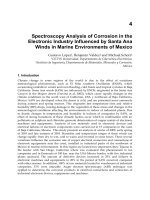
Climbing Robots
Gurvinder S Virk
University of Portsmouth
Portsmouth, Hampshire, UK.
gsvirk @ee.port.ac.uk
Abstract:
The paper presents an introduction to the main areas driving the
development of climbing robots; the reasons for the climbers arise because many
applications (including the nuclear and process industries, underwater operations,
forestry work and the construction sector) require robotic intervention due to the
hazardous environments encountered and because normal routes of access are not
available. The status of climbing robots is presented covering the machines
developed throughout the world with particular emphasis on the climbing
aspects. In addition the future requirements for such mobile machines and how
they can be achieved is described.
1. Introduction
Mobile robotics has received much attention in recent years with many innovative
designs produced and demonstrated at exhibitions and scientific meetings. The
driving forces for these machines (other than academic interest and general
enthusiasm) are hazardous applications where it is either impossible (or too
dangerous) to send humans to carry out particular operations of inspection, repair or
a specific function, such as fire fighting or transporting material and equipment to
inaccessible sites. There is a large variety of mobile robots and it is useful to classify
them in some sensible way. One possible approach is to partition them by their
locomotion technology as suggested in Virk [1]. Here the categories can be grouped
into wheeled vehicles, tracked devices and articulated legged machines. Or indeed
mobile machines can be classified into continuous or discontinuous locomotion with
the discontinuous machines further split into walkers or climbers or machines which
climb and walk. There are always some peculiar machines which cannot be put into
the chosen categories, for example the Roobot machine developed by Dr
Dissanayake at the University of Sydney has two legs and two wheels! There are
other particular mechanisms which propel themselves by crawling and/or other
submarinc type swimming devices or special purpose designs for operation in
particular environments such as in pipes or ducts (see the pipe climbing robot
developed by Naubauer [2], [3] shown in Figure 1). However such examples should
not stop us classifying mobile machines into some sensible grouping.
The intention of this paper is to concentrate on climbing robots so it is
convenient to classify the machines into climbing or walking devices (as already
mentioned, some can climb and walk!). This is especially relevant because the author
has recently instigated the setting up of an EC Brite EuRam Thematic Network on
Climbing and Walking Robots (CLAWAR). A six month study for this research
265
contract has highlighted the following needs for CLAWAR type machines (see Virk
[1]):
(i)
Nuclear industry:
here, there is a need for climbing and walking robots for
carrying out remote operations such as non-destructive testing, surface
preparation, hot spot localisation, and the retrieval of objects fallen in the
reactor vessel. Clearly there is a specific need for radiation hardened
components.
(ii)
Process industry:
here, climbing robots are required for the cleaning of
reactors, testing the integrity of the containing vessels and for monitoring
various processes. The chemical vessels may be part full, thus requiring that
the machines be chemical resistant.
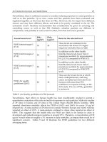
(iii) Outdoor applications: legged robots could be used for forest work (see the
Forest Walking Machine shown in Figure 2), land mine clearing (see Cornelis
et al [4], Nicoud [5]) and agricultural applications.
Figure 1: Pipe climbing robot Figure 2: Plustech's Walking machine
(iv) Construction: climbing robots can be used for inspection, remote handling
and window cleaning (see Seward [6]).
(v) Ship cleaning: climbing and walking machines can be used for cleaning the
inside and outside of ship hulls when in dry dock (some machines can operate
whilst the ship is still at sea).
All these present interesting and demanding challenges but we will be concentrating
here on the climbing aspects. When we refer to a climbing robot we normally mean
one which supports its weight off the ground. This means that wheeled machines
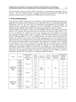
which can climb stairs or negotiate rough terrain (such as the Hobo machine shown
in Figure 3) is not classified as a climber. This seem sensible but some people have
argued to the contrary and it is difficult to be totally prescriptive about such things.
However the pipe climbing robot developed by Neubauer [2], [3], shown in Figure 1,
(which can climb vertically in ducts and pipes) is easier to accommodate within the
climbing group. In addition, the climbing and walking robot Robug IIs (shown in
266
Figure 4) developed at Portsmouth (see Luk et al [7]) clearly is a climbing machine;
it can walk and transfer itself onto the wall as well as climb up tall structures.
Figure 3: Kentree's Hobo machine Figure 4: Robug IIs
We start our discussions by looking at the overall technologies available for
designing and constructing climbing robots.
2. Technologies for Climbing Robots
The fundamental difference between a general ground-based mobile robot and a
climbing machine is that the climber has to be able to sustain its weight in its
operating environments. Many techniques have been developed to do this; these
include:
(i) special end effectors to hang from scaffolding, girders or limbs to push
against fixed structures (as for example the pipe climbing machine shown in
Figure 1);
(ii) magnetic devices to attach to steel structures such as tanks and walls; and
(iii) vacuum suction pads to grip to a variety of surfaces ranging from concrete or
brick walls, timber and other non-porous surfaces.
Each method has its good and not so good aspects, but high power-to-weight ratios
are important to ensure that weights of the machines can be supported (see Collie
[8]). There has been much work carried out in actuation technologies and how the
various methods compare in terms of power/weight ratios, bandwidth limitations and
individual characteristics (see Hollerbach et al [9], Colombi et al [ 10], Jezierski et al
[11]). It is widely acknowledged that the most potent form of actuation is hydraulics,
followed by pneumatics and then, lastly, electrical drives. However, hydraulic
systems tend to be disliked as they are heavy, suited to larger applications and prone
to leaking. Pneumatic actuators share many of the features of their hydraulic
counterparts but specific design and operating differences result from
(i) the lower viscosity of air relative to hydraulic fluid (by a factor of 1000);
(ii) the higher compressibility of air (by a factor of 300); and
267
(iii) the poor lubrication properties of air relative to hydraulic fluid.
Practical consequences of these aspects has meant that tighter tolerances have been
introduced to minimise leakage and fast-acting valves developed to counteract gas
compressibility. Most pneumatic actuators involve a piston driven by pressurised g~us
much in the same way as in hydraulic actuators. However inflatable elastic tubes or
bladders surrounded by a braided mesh that shortens with pressure have also become
popular. These type of actuators are commonly referred to as pneumatic muscles and
they offer the advantage of very high power-to-weight ratios (about 400:1) but their
life is restricted to about 10,000-15,000 cycles before they fail (Greenhill [12]).
There are other forms of actuation such as shape memory alloys and piezoelectric
devices (see Hollerbach et al [9]).
AXiS t~0
TIIIIiJilILL CtJI"I"iN VEHICLE, CAMERA AND
TOOL HeAD (X,Y,Z T(XX~e.~ ¢OmROL
AXES) ELECTRONICS
Figure 5: Mavis 3 machine
The two most common forms of actuation used for climbing robots use vacuum
suction and magnetic adhesion for the attachment method. Clearly the latter can only
work in situations where the environment is magnetically suitable, such as nuclear
installations or process plants for operation in metal tanks. Examples of such
magnetic climbing machines include:
•
Mavis (magnetically attached vessel inspection systems); this is a family of
vehicles which has been developed by Nuclear Electric plc and Sonomatic
Ltd (see Burrow and Yeomans [13]). Mavis 3 (shown in Figure 5) uses
permanent magnets which do not touch the vessel to stick onto the outside of
a Magnox reactor pressure vessel so as to provide work platforms to conduct
a variety of tasks aimed at extending the plant life. These tasks include ultra
sonic scanning, surface preparation via wire brushes and grinding and milling
operations. Traction for the vehicle is effected by the use of two independent
rubber belts driven by DC servos.
268
0
Robinspec (see Fortuna et al [14]), shown in Figure 6 attaches itself to the
walls of chemical reactors using three magnetic feet. This is a walking robot
designed for the inspection of storage tanks in the petrochemical industry.
Robinspec moves by means of its three legs (actuated by three independent
DC motors), each connected to the surface with two electro-magnets that
allow the robot to operate on vertical surfaces or upside down.
Figure 6: Robinspec magnetic robot Figure 7: Vacuum pad design
The vacuum suction technique is the most potent form of gripping
technique and one which has been applied by a number of researchers for various
applications, including nuclear, construction and ship cleaning. The workings of
these vacuum grippers is quite simple to understand and appreciate in that the
negative pressure created under the foot holds it onto the wall as shown in Figure 7.
The magnitude of this force (F) towards the wall is given by the product of the
vacuum pressure (P) and the gripper area (A). The conditions to avoid slipping and
falling are given by )1, and ~-) respectively, where W is the dead weight of
the robot, # is the frictional coefficient, h is the distance from the wall surface to the
centre of gravity and R is the distance from the centre of the gripper to the lower
h)1,
support point. If the robot is designed under the condition ~- ~- falling can be
avoided. The method can work on fairly rough surfaces by using appropriate seals
on the gripping pads so that good vacuums can be created. The two main methods of
creating the suction are to create a higher negative pressure by using a vacuum pump
or to produce a lower negative pressure by using a blowing device. With leakage
problems in practical situations the design must ensure that sufficient negative
pressure is maintained to support the robot as it moves even when rough surfaces are
being negotiated. It is possible to improve these leakage problems by using more
than one vacuum chamber so that the differential pressures and air losses are limited
giving rise to improved performances.
Most climbing machines to date have tended to concentrate on the
mechanical aspects so that the mechanical body and moving linkages are optimised,
but the sensors and decision-making have been largely neglected in the industrial
robots developed - in fact, most mobile robots fall in this category as well! The
269
reason for this has been that most industrial mobile machines have a user in the loop
who has been provided with sensor information such as CCD images and other range
data and environmental conditions to ensure that the operator can pilot the machine
in some sensible way. Various tele-operation systems and virtual environments have
been designed but now the emphasis is moving on to giving a degree of autonomy to
the machines. Such capabilities require significant investment and research in the
area of AI and autonomous decision making and are covered elsewhere in these
proceedings.
3. Applications
The main applications to date for climbing machines have been the construction,
nuclear and process industries and ship cleaning. The process industry applications
have concentrated upon using magnetic devices to attach to the reactor vessel and
using the machine as a platform for carrying sensors an manipulator devices for
cleaning operations. Tasks such as non-destructive testing and chemical analysis
have been carried out. The nuclear machines have been numerous and address
different scenarios encountered in the normal operation of a nuclear installation.
This ranges from refuelling, retrieval of objects fallen in the reactor vessel and
maintenance operations. In addition, the EC TELEMAN programme has specifically
addressed different scenarios. One project funded under this initiative was to
develop Robug III which was aimed at addressing a Chernobyl-type disaster and how
a lightweight mobile machine could be used both for retrieving nuclear material as
well as rescuing victims in such disaster scenarios. Robug III has been developed
under the TELEMAN 44 project by the Portsmouth consortium led by Portech Ltd
and involved several partners from Europe.
Clearly all the machines designed for nuclear applications need to be
radiation-hardened and must be easy-to-clean by, say, being able to be hosed down
after entering a radio-active environment. The machines need to be able to operate
in unstructured environments so they need to be able to walk on rough terrains but
when normal passages are destroyed they need to be able to climb vertical surfaces
and make various plane transfers such as floor-to-wall, wall-to-roof, wall-to-ceiling,
as well as internal and external wall-to-wall. Robug IIs and III machines developed
by the Portsmouth group has been designed to address these issues.
The Ninja climbing machine described in section 4 has also been designed
to perform some of these plane transfers which is felt to be an important capability
for climbing machines generally. In fact there are many questions which need to be
addressed when designing a climbing machine so that the required capabilities can
be included in the formal specifications for the vehicle; the example machines
discussed in section 4 will give an indication of these but the important points are
stated below in itemised form.
(i) Are plane transitions needed to be carried out?
(ii) Is walking and climbing required?
(iii) Will sliding mechanisms suffice or are articulated legs needed?
(iv) Is speed of the essence or will be slow operational robot be adequate?
270
(v) Are special environments to be encountered?
(vi) What is the level of autonomy needed in the operation of the robot?
The list can go on but it is useful to turn next to actual machines which have been
designed and built because this is the best way of illustrating the possibilities. By
being aware of what has been achieved it is then easier to make modifications to
allow different application specific climbing robots to be designed and constructed.
4. Machines Developed
The climbing machines developed to date have been numerous and only a few can be
included in a paper of this kind. The main activity has been in Japan and Europe and
some of the leading machines will be described here. The first of these is the Large
Sucker robot developed by Nishi [15]. The robot has a large vacuum gripper, tracks
for locomotion and is shown in Figure 8. The vacuum is created by using a fan to
suck air from under the foot to create the negative pressure which holds the machine
onto the wall when it is climbing. Similar machines to this include a simple suction
device called Big Foot at the University of Portsmouth. These designs are basically
inverted hovercrafts which suck rather than blow. By providing a locomotion facility
such as wheels or tracks under the skirt, these machines can travel vertically on most
construction materials and even on fairly roughly pointed brickwork. By using very
compliant seals small ledges can be negotiated and such a machine is able to travel
up vertical sheets of glass and window cleaning is one application where such
devices could be used.
Another climbing machine developed by Nishi [16] is the biped machine
shown in Figure 9. This is also based on vacuum suction grippers but has the ability
to make plane transfers using its hinged ankles and legs in an optimised manner to
minimise the moment on the fixed gripper. The biped has no specific operation in
mind but it is reasonably straightforward to insert a manipulator and/or additional
equipment on it for remote sensing and inspection purposes such as those required in
the construction industry.
Figure 8: Big sucker robot Figure 9: Biped walking robot
Nishi and Miyagi [17], [18] have also enhanced these designs to speedup
the access times required to climb up buildings by producing a Wall Driving Robot
271
as well as a Flight Robot which has been designed to fly over trees and other
obstacles and then attach itself to a building and start climbing for emergency type
applications such as fire fighting. Other machines have also been developed; these
include the Ninja machine developed by Professor Hirose in Japan (see Figure 10)~
and the Robicen developed by Professor Serna at the University of Navarra, Spain.
Information on these and other machines can be found in a recent report prepared by
the author (see Virk [1]), as well as on the world wide web in the Walking and
Climbing Machines catalogue set up by Dr Berns at Karlsruhe, Germany [19].
Figure 10: Ninja climbing robot Figure 11: Nero's sliding chassis design
Several interesting machines have been developed under the leadership of
Arthur Collie and John Billingsley at the University of Portsmouth in conjunction
with industrial partners (Portech Ltd and Nuclear Electric plc). These include:
Toad (see Billingsley et al [20]): This is a simple mechanism designed to
demonstrate walking on ceilings. It can be extended to include a spraying
system so that difficult tasks such as painting of ceilings can be carried out by
this device.
Figure 12: Nuclear Electric's Nero III climbing robot
The
Nero series vehicles (Nuclear Electric Robot Operator): These are
designed using a sliding chassis design shown in Figure 11, which can
272
negotiate difficult climbing surfaces such as dusty reactor vessels in nuclear
applications (see Luk et al [21], [22]). Nero I carries a tape feeder which has
been used to install pulley systems for hoisting equipment onto the nuclear
pressure vessel. Nero II has been designed to carry a rotary brush and vacuum
system to clean and carry away the debris. Nero III (shown in Figure 12) has
been designed to include an air-driven angle grinder which can cut through
steel bolt heads.
Robug
1~ (Luk
et
al [7]): The robot, shown in Figure 4, was designed
because the Nero machines exposed the need for a self-launching capability.
Robug IIs has an articulated body and four legs. Each leg has a vacuum
gripper foot designed along the lines discussed in section 2 and the body has
three furt
Figure 13: University of Portsmouth's Robug III
Robug HI (Luk et al [23]):
This is the latest machine designed by the group.
The machine has been funded under the EC Teleman program and its
specifications have been formulated by a user group comprising Nuclear
Electric, Electricite de France, European Authority for Nuclear Research and
the Italian Electricity Board. These specifications include the ability to
perform plane transitions, drag a 100 Kg payload while climbing, carry a
payload of 25 Kg, walk through narrow ducts and be able to operate in
unstructured environments. The machine is shown in Figure 13.
5. Future
To date most robotic systems have been developed along a one-off prototyping basis.
This has involved significant R&D costs for each individual project and there has
been little opportunity for cross-fertilisation between the projects. Consequently
there has been much re-invention of technology already developed and considerable
wastage of energy. The current financial climate for R&D is getting difficult and as
a result, such prototyping projects are becoming fewer and far between. Most
research groups are therefore turning to largely simulation studies or producing
small-scale robotic devices which have little industrial application. It is clear that
273
mobile machines will continue to be developed along the dual path of academic
research and application specific needs. However, the development cost in producing
one-off machines is enormous and is only affordable by just one or two application
areas where there is no other option.
However, having developed the core technology, it is felt that other "less
well off areas" could also benefit from deploying these machines. It is inevitable that
these new applications will require some revisions to the core design so that they can
be used effectively. A modular approach is felt to be required so that it is possible to
"mix and match" different modules to design application-specific machines in a
relatively straightforward manner. When such a philosophy is well established, it
would be much easier to identify missing elements or whether particular modules
need to be redesigned to satisfy some specific constraint (of size or power). Several
issues need to be considered in deciding on the most appropriate way of introducing
the modularity; these involve the flexibility of the researchers with the uniformity
and the different options offered by competitors. Communications protocol is a vital
aspect since this determines whether the different components will connect to each
other in a sensible manner. Consequently a thematic network for this technology area
has been set up under the EC Brite EuRam programme. Here the intention is to
provide a forum for the researchers to interact and maximise the future development
of such industrial mobile robotic vehicles.
6. Conclusions
The papers has presented the state-of-the-art in the area of climbing robots. The main
machines developed to date have been introduced and these show that the driving
forces are hazardous applications where there is a clear need for robotic intervention.
The most commonly used technique for climbing on surfaces is based on vacuum
suction grippers and many of the machines discussed here utilise this method. The
likely future development of mobile robots is also considered; it is expected that the
traditional one-off prototyping approach to robot design cannot continue for much
longer and there needs to be emphasis on re-using of the solutions already developed
elsewhere. T support such transfer of technology from one application to another,
greater thought has to be given to modularity and system integration issues so that
the different components can be combined much more easily. This is the aim of the
EC Brite Euram thematic network on climbing and walking robots being co-
ordinated by the author in collaboration with partners across the European
Community.
Researchers and scientists interested in mobile robotics vehicles are invited
to play an active part in taking the technology to its next logical stage - whatever this
may be! To do this simply contact the author so that you may be included in the
activities of the CLAWAR Network.
7. References
[1]
Virk GS; EC Brite Euram III Thematic Network on climbing and walking
robots, Exploratory Phase CLAWAR Report, University of Portsmouth,
January 1997.
274
[2]
[3]
[4]
[5]
[6]
[7]
[8]
[9]
[lo]
[11]
[12]
[13]
[14]
Neubauer W; Locomotion with articulated legs in pipes or ducts, Proceedings
on Int Conference on Intelligent Autonomous Systems, pp 64-71, Pittsburgh,
Feb 1993.
Neubauer W; A spider-like robot that climbs vertically in ducts or pipes,
Proceedings Int Conference on Intelligent Robots and Systems, Vol 2, pp
1178-1185, Munich, Sept 1994.
Cornelis J, Sahli H, Acheroy M and Baudoin Y; Anti-personal mines, a
worldwide problem: From political conscience towards humanitarian,
research and industrial action, Proceedings of the 6 th Int Symposium on
Measurement and Control in Robotics (ISMCR 96), pp 1-5, Brussels 9-11
May 1996.
Nicoud J-D; Mine Clearance: not only a problem for the military any more,
Proceedings of the 6 th Int Symposium on Measurement and Control in
Robotics (ISMCR 96), pp 6-10, Brussels 9-11 May 1996.
Seward D; Robots in construction, Industrial robots, Vol 19, No3, pp 25-29,
1992.
Luk BL, Collie AA, Bevan N and Billingsley J; An articulated limb climbing
vehicle with autonomous floor-to-wall transfer capability, Proceedings of 1st
IFAC Int Workshop on Intelligent Autonomous Vehicles, pp 20-24,
Southampton, April 1993.
Collie AA; Unusual robots, Industrial robots, Vol 19, No4 pp 13-16, 1992.
Hollerbach JM, Hunter IW and Ballantyne J; A comparative analysis of
actuator technologies for robotics, The Robotics Review, Vol 2, pp 299-342,
MIT Press, Cambridge, 1991.
Colombi S, Raimondi T and Costi G; Improvements of actuators in tele-
operators, Proceedings of the 4 th Int Symposium on Offshore robotics and
Artificial Intelligence, Marseille, pp 501-507, 11-12 December 1991.
E W Jezierski, A Bartoszewicz and K Mianowski; Teleman 44: Manipulator
arm development and end effector design, Final Report, University of Lodz,
1996.
Greenhill R; Private communication, The Shadow Group Project, 251
Liverpool Road, London N1 1PX.
Burrows MS and Yeomans D; Magnetically attached vehicles for a reactor
pressure vessel inspection, Proceeding of conference on Remote techniques
for nuclear plant, organised by the British Nuclear Energy Society, pp 152-
156, Stratford-upon- Avon, May, 1993.
Fortuna L, Gallo A, Giudice G and Muscato G; Robinspec: A mobile walking
robot for the semi-autonomous inspection of industrial plants, WAC 96,
Montpellier, May 1996.