Anatomy of a Robot Part 10 pdf
Bạn đang xem bản rút gọn của tài liệu. Xem và tải ngay bản đầy đủ của tài liệu tại đây (248.4 KB, 20 trang )
This is especially true if no power supply circuitry exists and the robot is running
off the battery directly.
■ Internal resistance Batteries will all have different internal resistances. This
behaves much like a resistor in series with the battery. As the battery ages, this
resistance may change. When a motor or other heavy load, places a sudden
demand on the battery for current, the voltage of the battery will change quickly.
Make sure the rest of the robot’s control circuitry and sensitive instrumentation
can take the sudden voltage transient on the power supply.
■ Lifetime Don’t forget that the ability of batteries to store energy will change
over time. Many types of batteries (with different internal chemistry) will lose
their capability to store power as the battery ages. Within the battery, chemicals,
gases, and metals migrate or slowly corrode so they are no longer able to fully
contribute to energy storage. Make sure the robot’s circuitry will be able to func-
tion just as well when the robot and its batteries reach old age (see Figure 7-2).
Power Requirements
If we are trying to power a robot using just the battery as our power supply, we need to
limit the number of different voltages that will be needed within the robot. This may
mean that all the electrical components must be selected so they can work off the same
voltage. This becomes quite a challenge when we try to pick motors, sensors, and com-
puters that all have similar requirements for voltage. So what voltage should we try for?
High voltage, for example, is not a good choice for running computers or most sensors.
Motors To complicate things further, low voltage does not work well to move motors.
We can use very low voltage drop Field Effect Transistors (FETs) to control the motor
166 CHAPTER SEVEN
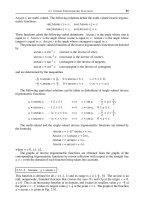
FIGURE 7-1 Battery voltage varies during a discharge cycle.
Battery Discharge Curve
Volts
Time
07_200256_CH07/Bergren 4/10/03 3:30 PM Page 166
windings and keep the efficiency up. Semiconductor companies sell chips specifically
designed to control motors in an efficient manner. Some low-voltage motors are avail-
able, but it would restrict our choices. Many motors are available that require a 12-volt
drive. Fewer are available that will work with a 5-volt drive. The requirement to turn the
voltage off and on to a motor further complicates the supply question because most volt-
age switches (and wiring) will also drop the voltage available to the motor.
Several alternatives also exist to traditional motor technology. Esoteric motors may
be fun to investigate, but use them with care. The motor found at www.drives.co.uk/
news/prodnews/news_prodnews148.htm, for example, uses piezoelectric power to
create movement and uses low voltage.
Control Systems Most computers are designed to work from power supplies in the
3- to 5-volt range. We’ve discussed processor technology before, including power sup-
ply requirements, but one aspect of the computer technology we did not touch on is rel-
evant to battery-powered robots in particular. Control system circuitry made from
Complementary Metal Oxide Semiconductor (CMOS) technology has certain advan-
tages in this application. CMOS semiconductor technology, aside from being a
ENERGY CONTROL AND SOFTWARE 167
FIGURE 7-2 An elderly robot toy
07_200256_CH07/Bergren 4/10/03 3:30 PM Page 167
low-power technology as discussed previously, also has two other nice characteristics
we could use:
■ High noise margins Most semiconductor technologies, such as bipolar and
some FET technologies, have strict requirements for the voltage levels that can be
present on the circuit board. Processors and integrated circuits made from these
technologies have signals that only vary over a small percentage of the power sup-
ply voltage range. If the signals vary outside of these ranges, then logic errors
might occur and the robot will malfunction.
CMOS FET technology can tolerate a much wider range of signal voltages. With
some restrictions, CMOS logic gates regard signals above 50 percent of the power
supply voltage as logic one, and signals under 50 percent of the power supply volt-
age as logic zero. The power supply can even change voltage (within bounds) and
CMOS logic gates will still work just fine. It may be difficult to find off-the-shelf
computers built with just CMOS because the competing bipolar technologies have
the bulk of the commercial market, but certain manufacturers concentrate on
CMOS and other logic families cater to the requirements of portable and robot
applications. It should also be noted that some logic families work better than oth-
ers in the presence of nuclear radiation. If your robot will be going to truly hot
locations, give CMOS a good look!
Here are some PDF files that discuss high noise margin logic:
■ www.ece.pdx.edu/~greenwd/AN_375.pdf
■ />hc-cmos-dc-characteristics.pdf
■ Power supply range CMOS technology will work over a relatively wide range
of power supply voltages. Most single board computers (SBCs) work off 5 volts,
but it’s not impossible to find boards that will accept a wider voltage range. Auto-
motive designers have been using CMOS and related chip technologies for years,
even though they are not stuck for energy.
Here are some sites providing information about CMOS logic families:
■ www.bychoice.com/cmos.htm
■ />■ www.electronicstalk.com/news/sra/sra100.html
Power Regulation
Energy is not always available in a form that can be used successfully. Often, it has to
be transformed and tamed. This can be done in a few different ways and some are more
168 CHAPTER SEVEN
07_200256_CH07/Bergren 4/10/03 3:30 PM Page 168
suitable than others for battery-powered robots. It’s time to review power regulation and,
in the bargain, we can take note of regulation techniques that are good for robots.
The central problem to be solved in power regulation is to prepare an untamed energy
source to provide tame power for the robot. Certainly, the type of tame power needed
by the robot will vary. In some instances, the robot’s circuitry can use unregulated Direct
Current (DC) or Alternating Current (AC) to power components like motors or sole-
noids. But in most cases, the robot’s components will need well-regulated DC power.
This type of power is generally specified by the voltage, the acceptable voltage range,
the current available, and the level of ripple that can be tolerated. For some 5-volt DC
supplies, the specifications might read: “5V ϩ- 0.25V, 5A, 25 mv pp ripple.” This is a
power supply that can deliver 5 amps into the robot at a voltage between 4.75 and 5.25
volts with only 25 millivolts of ripple noise. The ripple noise is often 60 Hz of noise (on
supplies driven by the AC power) or a higher frequency from a switching action that
will be discussed shortly.
Unstated specifications for a power regulator include the following:
■ Efficiency Although our example power supply might deliver 25 watts into the
robot (5V ϫ 5A), it might require a feeder wattage of 40 watts to do so. That
would make its efficiency 25/40 ϭ 62.5 percent. The power regulator alone wastes
37.5 percent of the energy.
■ Emissions Power supplies generate interference (electrical noise and radiation),
which propagates out all the power connections and through the air. Since com-
pliance with regulatory bodies is often required (as mentioned in Chapter 4), we
must pay attention to the power supply as part of this effort.
Types of Regulators Power supply regulators are available in many forms, including
the following:
■ Linear regulators Linear regulators are an older technology that is well char-
acterized. One or more large transistors take the unregulated power at a higher
voltage (Vin) in one side and deliver regulated power at a lower voltage (Vout) out
the other side. By and large, since the current flows linearly through the power
supply, Efficiency ϭ Vout/Vin.
Generally, the larger the difference between Vout and Vin, the better the power
supply, keeping noise spikes on Vin from getting to Vout. Unfortunately, this low-
ers the efficiency. Also, more cooling may be necessary; the power supply tran-
sistors may need larger heatsinks. Linear regulators are relatively simple and can
be reduced to a single three-terminal component with connections for Vin, Vout,
and Ground. They do not generate significant electrical interference, but they are
not very efficient as a rule.
ENERGY CONTROL AND SOFTWARE 169
07_200256_CH07/Bergren 4/10/03 3:30 PM Page 169
The following PDF files contain basic information about both linear and switch-
ing power supplies:
■ www.web-ee.com/primers/files/f4.pdf
■ www.web-ee.com/primers/files/AN-556.pdf
An offshoot of linear regulators is the Low Drop Out (LDO) regulator. LDOs are
linear regulators that expect a very low difference between Vin and Vout. They are
used primarily for the local regulation of voltage or in situations where Vin is very
low and Vout must be as high as possible. Since the efficiency is high (Vout/Vin),
LDOs generally do not need large heatsinks.
LDOs can be used for distributed regulation. Instead of having a single power sup-
ply in the robot, Vin is distributed throughout the robot and sent to several LDOs,
which provide regulated Vout power to different parts of the robot.
■ Switching regulators Switching regulators are generally more efficient than
linear regulators. In addition, they can perform feats like making Vout higher than
Vin, but this does not mean the efficiency is higher than 100 percent. Because cur-
rent does not flow linearly through a switcher, the efficiency cannot be easily
computed.
Switchers basically take Vin and convert it to a high-frequency AC voltage wave-
form. This high-frequency current is transformed in various ways to a raw DC
voltage that can be higher or lower than Vin. Then the AC components are re-
moved to form Vout, an action made easier because these AC components are high
frequency and are easily filtered out. The following PDF files have further expla-
nations of this process:
■ www.web-ee.com/primers/files/webex9.pdf
■ www.web-ee.com/primers/files/f5.pdf
Switchers can run at a very high efficiency (above 90 percent) when used care-
fully. In practice, don’t count on achieving the claims made by the manufacturer.
Count on 75 percent and be surprised if the real number comes out higher. But in
a robot, this type of power supply can conserve energy. The downside is that
switchers will generate significant amounts of electrical interference of all types.
PROCESSOR
All further considerations of hardware energy savings must start with the processor. The
processor has several energy-saving features, which we have discussed before, and they
are outlined in the following sections.
170 CHAPTER SEVEN
07_200256_CH07/Bergren 4/10/03 3:30 PM Page 170
Power Supply Voltage
Most low-power processor chips designed for energy-efficient systems can function
with very low voltages. We’ll see why this is important when we discuss CMOS logic.
Suffice it to say that energy consumption is proportional to V
2
. This square law of
physics pays us great dividends as we move to lower and lower voltage systems. If we
can cut the voltage in half, the energy consumption goes down by a factor of 4!
Varying Voltage
Further, some processors can function while the power supply voltage varies. If the
processor has this feature, we can take advantage of it in the following way. Because
higher voltages can charge up capacitances in the logic chips faster, the computer can
run faster at higher voltages. If the computer has little to do, we can lower the voltage
and decrease the clock frequency, and the energy draw goes way down. As long as the
processor can get its work done in the allotted time, then the robot will function prop-
erly and all is well. In the mean time, a great deal of energy will be saved.
To take advantage of this feature, the power supply must be under software control.
It must initialize to a suitable voltage and then provide the proper controls that will
enable the computer software to alter the processor power supply voltage to acceptable
levels. It’s possible to get by with a single digital input that alters the power supply volt-
age. Just make sure that the slew rate of the power supply voltage (the first derivative)
is small enough and remains within the limits the processor can accept.
Varying Clock
Processors can be built out of CMOS. All logic families have a basic building block
called an inverter. The CMOS inverter is special in that it does not enable the current to
flow except when it changes state. Thus, if a CMOS inverter stays static as logic one or
logic zero, it will not use energy. However, when it changes state, the capacitance within
the inverter must be charged up (changing to a 1) or discharged (changing to a 0). When
this happens, a distinct amount of energy is used up in the capacitance of the inverter.
The energy in this capacitance is
where V is the power supply voltage and C is the capacitance of the CMOS logic
inverter gate.
Ecap ϭ 0.5 ϫ C ϫ V
2
ENERGY CONTROL AND SOFTWARE 171
07_200256_CH07/Bergren 4/10/03 3:30 PM Page 171
Since this amount of energy is dumped every time the CMOS inverter changes state,
the power exerted is proportional to
where f is the frequency of the processor clock.
Since the capacitance C is fixed by the CMOS process, it’s clear that our best hope
for power savings is to decrease V and f. Some modern processors are built to withstand
this. Changing their power supply voltage and changing their clock frequency will
decrease their power consumption.
Care must be taken, however, that the processor clock is not used for any fixed fre-
quency processes within the robot. Communication interfaces, for example, often
require a special fixed frequency for operations. Make sure these interfaces have their
own fixed clock frequency. The central clock of the system can first feed into these
communication interfaces and then it can be divided down for the processor. Some
processors have all this clock division circuitry internal to the processor.
The voltage and the clock can be ramped up and down to fit the workload of the
processor. Figure 7-3 shows the method of ramping voltage or the clock up and down,
and the relative effect on the processor performance. The same amount of work gets
done in the second graph, but since the voltage is half, the power dissipation for that
P ϭ Ecap ϫ f ϭ 0.5 ϫ C ϫ V
2
ϫ f
172 CHAPTER SEVEN
FIGURE 7-3 A computer can save energy by running longer at a lower
voltage.
Compute activity, V is high
Time
Compute activity, V is low
Time
07_200256_CH07/Bergren 4/10/03 3:30 PM Page 172
work is a quarter of what it would have been. An interactive tutorial on CMOS can be
found at />Processor Power States
As we’ve mentioned before, processors have distinct energy-saving states. Pick a pro-
cessor that has the types of energy-saving states that will match the operating require-
ments of the robot you are building.
Further, if the robot is to operate in a remote environment (with some remote con-
trol), consider giving the operators the ability to alter the processor power state from
afar. This is a feature that may just “save the bacon” of the project team someday. Those
reading translations of this text are now rather quite confused at this porcine idiom. As
an experiment, I have fed this paragraph to a computerized translator and translated it
from English to German and back. Before considering building a robot translator, read
the next paragraph. I’m sure it will give my editor fits. The two translations follow. Try
it yourself at />Here’s the automatic translation into German:
Weiter wenn der Roboter in einer Aussenstelle funktionieren soll (mit etwas
Fernbedienung), betrachten Sie, den Operatoren die Fähigkeit zu geben, um den
Prozessorenergie Zustand von fern zu ändern. Dieses ist eine Eigenschaft, die ger-
ade save der Speck kann. von der Projektmannschaft eines Tages. Die Leseüber-
setzungen dieses Textes sind jetzt an diesem schweineartigen Idiom eher ziemlich
konfus. Als Experiment habe ich diesen Punkt zu einem automatisierten Überset-
zer eingezogen und ihm von englischem zum Deutschen und zur Rückseite über-
setzt. Bevor Sie einen Roboterübersetzer errichtend betrachten, lesen Sie den
folgenden Punkt. Sicheres I.m gibt er meinem Herausgeber Sitze. Die Überset-
zung folgt. Versuchen Sie sie sich an />Here’s the automatic translation back to English again:
Far one if the robot in a branch office to function is (with something remote main-
tenance), regards you, to give to the operators the ability in order to change the
processor energy condition from a distance. This is save a characteristic, the
straight the bacon can from the project crew of a daily. The read translations of this
text are now considerable at this pig-like Idiom rather konfus. As experiment I
drew in this point to an automated translator and him from English to the German
and to the back translated. Before you regard a robot translator establishing, read
ENERGY CONTROL AND SOFTWARE 173
07_200256_CH07/Bergren 4/10/03 3:30 PM Page 173
the following point. Safe I’m it gives to my publisher of seats. The translation fol-
lows. Try it on />Oh well.
Processor Power Draw
Some processors are simply designed for low power operation, and others are not. Don’t
even bother considering processors that do not have the types of features necessary for
low power operation. Restrict the search for a processor to suitable energy-saving
processors.
Memory Types
When selecting memory technology, pay attention to the power draw of the memory
chips themselves. In particular, some flash memory chips have a built-in energy-saving
feature. They will move to a low power state if they are not accessed within a certain
time period. This can significantly decrease power consumption with little effect on the
operating speed of the processor.
SUBSYSTEM POWER CONTROL
The robot’s subsystems should be designed with integral power control switches. The
processor, under software control, should be able to turn off the power to unused por-
tions of the robot. If, for instance, the robot will be still for a while, we may be able to
turn off all power to the actuators and motors. If the robot does not have to sense any-
thing for a while, we can turn off the sensors. A variant of this sort of power control
switch is a “dead man” power controller that will turn off subsystem power unless the
processor commands otherwise. This is useful in situations where the processor may
bomb or if the application software simply forgets to do the proper housekeeping.
Remote, unattended robots need this sort of hardware feature on subsystem power con-
trol to avoid accidentally draining the batteries.
DRAIN ON INTERROGATION
Try to use sensors that do not consume power unless they are being interrogated. For
simple digital inputs, consider using tri-stated processor inputs. Often, it’s possible to
avoid any energy drain except during the brief period where the processor is interro-
gating the input.
174 CHAPTER SEVEN
07_200256_CH07/Bergren 4/10/03 3:30 PM Page 174
PATH CHECKING
During the design of the robot, be sure to check every single path that current might
take to ground. Often, sneak paths can unexpectedly develop that can drain a battery.
Don’t assume that all wires, connections, and components are one-way conductors of
current. Often, current will flow backwards through a component to provide an unfore-
seen path. This can drain a battery completely. Robots designed for remote locations
(like Mars) are routinely examined for these sorts of sneak paths. For critical missions,
determine what happens if a component fails completely. Will it fail as a short? Will it
fail open? What is the backup plan for preventing energy losses in such an occurrence?
SENSOR THROTTLING
Since the computer cannot pay constant attention to the sensors anyway, consider turn-
ing them off when not in use. Be careful though; choose sensors that have no warm-up
time. Often, sensors will drift for a while after they are turned on. If the sensors have
integral, internal references and remain accurate with power cycling, they may work
well. If the computer must recalibrate the sensors every time they are turned on, it may
not be worth it.
PERIPHERAL POWER CONTROL
Many peripherals are available with internal power control circuitry. Sometimes the
power controls work automatically within the peripheral, and sometimes the program
controls them directly. Such peripherals are as follows:
■ Hard drives Hard drives can be turned off so they spin down. Most computers
offer this option now. Once the disk spins down, it will take a few seconds of latency
time for any new data; the disk must spin up to speed before data will be available.
■ Displays Most computers now have control over the display’s consumption of
power. On laptops, the backlighting is controlled and desktops control the moni-
tor itself. These components use up quite a bit of energy. If the robot has a require-
ment for a display, make sure the relevant controls allow control of the energy
consumption.
■ Communication interfaces Communication interfaces carry data into and out
of the robot. For robots that are short on available energy, the communication
interfaces must be thought through very carefully. One of the most difficult prob-
lems to work through is monitoring the communication inputs. It takes energy to
monitor a communication input continuously. The next section covers a few devel-
opments that may help with this problem.
ENERGY CONTROL AND SOFTWARE 175
07_200256_CH07/Bergren 4/10/03 3:30 PM Page 175
Spy-hopping
Some whales have an unusual practice of rising out of the water to see what is going on
above the water line (see Figure 7-4). It gives them some visibility they might not have
while underwater. Interfaces also spy-hop to detect network activity. The interface only
looks at the network periodically so energy use is minimized when no activity exists.
■ Spy-hopping networks Peripheral network interface chips are available that can
monitor the network periodically to see if there are messages. Other interface
chips are capable of waking the system up from a power-saving slumber when a
message destined only for the robot appears. The rest of the time, the interface cir-
cuitry is turned off to save energy.
■ Spy-hopping energy detection It takes more circuitry to detect specific data
patterns than it takes simply to detect data activity. Some communication inter-
faces will sleep until they detect a sufficient amount of energy at the communi-
cation input. This works best in a communication link where there is little traffic
that is not meant for the receiver (like a narrowband radio frequency [RF] link).
This type of wakeup does not work well in networks where all interfaces share the
same physical link, differentiated only by addressing.
■ Spy-hopping time coordination If both ends of a communication link agree in
advance to limit communication to distinct time windows, neither side of the link
176 CHAPTER SEVEN
FIGURE 7-4 A whale spy-hopping
07_200256_CH07/Bergren 4/10/03 3:30 PM Page 176
need bother watching its receiver until the appointed time. Such a communication
protocol can save quite a bit of energy. Certainly, both ends of the link must have
accurate, free-running clocks to remain coordinated. An alternative is to use a
commonly available clock such as one transmitted by GPS satellites that is avail-
able all over the world.
SOME NOTES ABOUT SPY-HOPPING
Spy-hopping is basically a way for the robot to periodically sample the world in which
it must function. As we will see in Chapter 8, sampling can easily get the robot in trou-
ble. Two conditions make it possible to use this technique. First, conditions must be well
known for sampling to be effective. Second, the control system must be able to func-
tion properly with the limited amount of information that proper sampling techniques
afford.
We should note at this point that spy-hopping is inherently a type of polling. The
robot’s control system takes on the responsibility of watching events and catching them
as they happen. The processor software goes to each interface periodically and “polls”
it to determine if it needs attention. This control method is distinctly different from
interrupt-driven control systems where it is up to the event itself to notify the con-
trol system that action is needed. Interrupt systems also are capable of low-power
operation.
Since spy-hopping relies on sampling, an inherent response time delay is built into
the control system. If an event of interest occurs, it will be some time before the proces-
sor wakes up and polls the sensors monitoring the event. As long as the event lasts long
enough to be detected, the processor will catch it and act properly. A delay will take
place, however, which might be as long as the spy-hopping interval. As long as the con-
trol system can perform its tasks effectively in the face of the delays, no problems occur.
ADAPTIVE SPY-HOP DUTY CYCLE
The robot’s control software can adapt to a changing environment. If the control soft-
ware notes that relevant events are occurring ever more frequently, it can decrease the
spy-hopping intervals. Sampling the environment more often will help guarantee
smooth operation, but at the expense of increased energy consumption. When the
robot’s control software senses that external activity is slowing down, it can increase the
spy-hopping intervals again to save power. This technique can be used in situations
where the environment changes in a relatively predictable way. If the adaptive control
software alters the spy-hopping interval fast enough to keep track of the changing en-
vironment, then all will be fine. If the environment changes faster than the control
ENERGY CONTROL AND SOFTWARE 177
07_200256_CH07/Bergren 4/10/03 3:30 PM Page 177
system can adapt, problems will arise. The spy-hopping interval may remain too large
to effectively sample the sped-up environment. If limits exist on the rate of change in
the environmental processes, then the adaptive control system can be designed to keep
up. But if no definitive boundaries exist for these processes, be wary of adaptive con-
trol loops within the robot. It might be better just to waste the extra energy and let the
control system run at the fast rate, rather than risk a control system problem.
Software Considerations for
Energy Control
As discussed before, only hardware can conserve energy since it’s the only consumer.
Most of the hardware features capable of conserving energy will probably be under the
direct control of the software. Many techniques for using software to save energy bear
mentioning.
OPERATING SYSTEM
We’ve already discussed some of the operating system (OS) hooks that can be used to
conserve power. By and large, the very presence of an OS is antithetical to the proper
functioning of a parsimonious energy conservation system. We won’t discuss this much
further since each OS will have its own documentation for such matters, but be careful
that the OS properly supports the energy conservation states of the processor that is run-
ning the OS. If the OS has not been properly ported to the processor, or if the OS does
not support energy conservation, then consider another one.
One of the key features of an OS that we’ve mentioned is the handling of the soft-
ware environment. The OS must be capable of storing and retrieving software environ-
ments so it can survive power failures. During the initial system engineering of the
robot, we must decide what the implications of power failures are. If the robot must be
able to survive a brief interruption of power, then special hardware and software con-
siderations must be made. We’ll discuss these in the section on power failures.
ALGORITHMS
We can tailor algorithms to conserve power. The central idea is that each individual
operation in a control algorithm, each and every executed instruction step, consumes
178 CHAPTER SEVEN
07_200256_CH07/Bergren 4/10/03 3:30 PM Page 178
power. We can alter the algorithm so fewer steps are required and thus save power.
Certainly, algorithms can be structured many different ways, but to save power, keep
them short and sweet.
SCHEDULING
To coin a phrase, one should better buy the pizza instead of just eating it by the slice.
Certainly, buying the whole pizza at once will be cheaper, and the same is true in the
software domain. It becomes easy to chop a control problem into tiny pieces without
realizing it. Often, this happens during the design process as various aspects of the
power control problem are considered one at a time. Once a problem is chopped into
pieces, we wind up paying for it in lost compute time, lost energy, and lower reliability.
Problems become fragments in more than one dimension. Here are a few ways to
decrease wasted overhead in the robot:
■ Computer overhead A computer control program that executes intermittently
is wasteful. The robot’s computer must be awakened or used more often, and the
attendant overhead becomes excessive. If we can find a way to pull the program
back together so it can be handled in one fell swoop, we can reclaim the lost
energy and time. Consider auditing all the tasks the robot performs and identify-
ing those that are being handled in a fragmented way. Several such tasks creep
unnoticed into a design during the design phase. Rewriting those tasks will often
bring power savings and make the software more reliable.
■ Power overhead Most robots have dozens of tasks to perform. Some of the
energy to perform these tasks will be wasted in overhead. Consider, for the
moment, a car. Starting a car, at the very least, causes energy to be expended from
the battery. If we have two errands to run, we could group them together so we
only have to start the car once. The same grouping technique can work in energy
management in a robot. Some of the hardware circuitry will need to be charged
up to perform tasks. We can save energy by grouping tasks together in time so less
energy overhead is wasted.
■ Pipelining (real time) Consider modifying the robot’s control software to
pipeline tasks. To illustrate why this is useful, we need to revisit pipelining as it
applies to processors.
In processors with pipelines, instructions are not executed immediately, but they are
put into a pipeline. Pipelines can be used in different ways to control energy consump-
tion or execution speed. A trade-off takes place between speed and power since more
compute power requires more energy.
ENERGY CONTROL AND SOFTWARE 179
07_200256_CH07/Bergren 4/10/03 3:30 PM Page 179
Pipelines for Speed
In Chapter 3 on computer hardware, we discussed using pipelines to speed up process-
ing. The specific example used was “If A, then B, else C.” In a pipeline optimized for
speed, A, B, and C are put into the pipeline simultaneously and are computed simulta-
neously. Either B or C comes out of the pipeline (already precomputed) based on the
value of A. This is the way a pipeline optimized for speed would behave. It burns energy
as fast as possible.
Pipelines for Power
As the processor goes about executing the instructions inside the pipeline, it sometimes
notices that some of the instructions don’t have to be executed. Power can be saved if
unneeded instructions are not executed. Let’s revisit our example program, “If A, then
B, else C.” In a pipeline optimized for power, A is put in the pipeline and computed
first. Based on the value of A, either B or C is put into the pipeline for computation.
This method is clearly slower but saves the energy that might be used in unneeded
computations.
We just looked at how a pipeline in a processor can be optimized for energy conser-
vation. The processor has a pipeline that handles instructions that are executed in a serial
manner. In the same manner, we can construct a pipeline of tasks that the robot executes
in a serial manner. If we buffer up these tasks instead of executing them immediately,
we may discover tasks that do not have to be executed. In a real operation, various com-
mands may arise that just don’t make sense. One set of commands might look like this:
“Go to from Point B to Point C and pick up the Rock C. Bring it back to Point B and
examine Fact A. If A is true, drop Rock C and pick up Rock B.”
A properly constructed robot task pipeline would look at this series of commands and
alter it to the following: “Examine Fact A. If A is true, pick up Rock B, or else go to
Point C and pick up Rock C.”
A very well constructed robot task pipeline would question whether the robot should
do any of this work. If neither the information about fact A nor the rocks are needed in
subsequent tasks, all this work can be avoided. If a subsequent robot task requires Rock
B or Rock C, then the pipelined tasks can be executed. Further, the robot task pipeline
can determine if the robot really needs to return to Point B at all.
Most people, while cleaning house, will find lots of reasons to go upstairs and down-
stairs to achieve specific goals. If no emergencies occur, it makes sense to pipeline all
the tasks for a while. Go upstairs for the upstairs tasks and downstairs for the down-
stairs tasks. It’s easy to tell that this saves energy. If the robot can afford to hesitate for
a while, it can pipeline its tasks and probably save some energy.
180 CHAPTER SEVEN
07_200256_CH07/Bergren 4/10/03 3:30 PM Page 180
Pipelining (Premission)
Just as the robot’s computer can pipeline tasks, so too the robot designers can pipeline
tasks well in advance. It’s just a matter of how soon the logical order of execution can
be determined. In the case of real-time pipelining, the robot’s computer pipeline is strip-
ping out tasks that have been cobbled together at the last moment. The real-time pipeline
optimizes tasks that don’t make sense because they could not be predicted beforehand.
But with clever programming, the robot’s designers can also optimize ahead of time the
ways in which tasks are executed. It’s almost like performing pipelining well before the
tasks are to take place, and then feeding the robot’s real-time pipeline a stream of tasks
that don’t need any further optimization.
Consider a trivial example. Suppose the robot has “shoes” that are required for move-
ment. It does not take a genius to realize that putting on shoes should be done before
standing up. Those of us with kids, however, know the kid’s already up, in the car, and
down to the mall before we discover the surplus of pink wiggly toes. Given that humans
are leaps and bounds ahead of robots in their abilities and evolution, we leave it to the
reader to discover the advantage this sort of behavior conveys to the human species.
Why is the world put together like this? Once we, as humans, become smart enough to
discover the reason, we will surely build superior robots.
But I digress. The robot designers should be able to plan missions where the robot is
controlled well enough to put its shoes on before moving. In fact, with the proper devel-
opment software, the premission planners should have the tools that will make proper
robot control largely an automatic occurrence.
Taking one step back, robot designers should also be able to optimize all the software
instructions to conserve power. We’ve already seen the example of the IF instruction
optimized for speed or power. Most compilers are capable of optimizing the software
for various things. With certain flags set at compile time, a compiler can turn out fast
code or condensed code that uses little memory. A good compiler will also eliminate
code that will never be executed.
SAFEGUARDS
The robot’s control software should have control loops that will sense the inordinate
consumption of power and other serious situations. This is especially vital in space mis-
sions or when the robot cannot be repaired. Two types of events should be watched care-
fully with separate software watchdogs:
■ Security breaches Communication coming into the robot should be scanned for
evidence of hackers and other more random interference. If it’s determined that
ENERGY CONTROL AND SOFTWARE 181
07_200256_CH07/Bergren 4/10/03 3:30 PM Page 181
the system is under attack, it should move to a safe configuration and shift its con-
trol strategies. The robot should report the intrusion once it’s detected, and then
secure the robot’s energy supply against unwarranted use. Energy can be con-
served while proper communications are restored.
■ Power thrashing Given that the energy supply is of critical importance in many
mobile robots, it makes sense to observe the power drain carefully. If the energy
is being drained away too quickly, it makes sense to shut down activities until the
cause can be determined. The robot may be thrashing about, malfunctioning, or
just executing a badly designed algorithm. It’s a smart robot that will give itself a
timeout.
POWER FAILURES
One technique that is all but lost in today’s complex world of computer software is the
use of power failure detection. It is possible to build a power supply with an output sig-
nal called Power Failure Detect (PFD) that will warn of the impending cessation of
input power. During a power failure, the PFD signal can go low a few milliseconds in
advance of the time when the regulated power will fail to meet specifications. The
processor will be interrupted and can do all the housekeeping necessary to survive the
event. If the robot is designed from the start to take advantage of this, then it is possi-
ble for the robot to pick up right where it left off. To plan on using this capability, we
must solve all the following problems:
■ The power supply must generate the PFD signal reliably. Most power supplies do
not have this feature.
■ The OS software must facilitate the implementation and use of the PFD signal.
The truth is, most OS software will simply get in the way of successfully imple-
menting PFD software. Most large OS software products have so many holes and
gaps that success is problematic.
■ The robot’s computer must have sufficient nonvolatile memory to put away all the
volatile data that will be lost during the power failure. Flash memory, battery-
backed Random Access Memory (RAM), and disks are all good places to put the
data. Once a PFD is signaled, however, we must be very careful to finish all oper-
ations before the power fails completely.
■ All the robot’s states must be put away to accomplish a complete PFD recovery.
These states include both the digital states that we have been talking about and
mechanical states. The robot, after all, may be moving when the power fails. It is
likely that the movement will be disturbed by a power failure unless the power fail-
ure is very short. Consider the case where the robot is moving its arm to the right.
182 CHAPTER SEVEN
07_200256_CH07/Bergren 4/10/03 3:30 PM Page 182
If a very brief power failure occurs, proper PFD software will preserve that infor-
mation and finish the movement when the power returns a few milliseconds later.
Certainly, if the power failure lasts longer, the motion will be ruined anyway. In
addition, if safety requires it, all motions must come to a fail-safe stop when the
power goes down. In all these instances, a complete PFD recovery of mechanical
states is impossible.
Mechanical Considerations: Software
for Energy Control
We’ll be discussing some mechanical engineering in Chapter 11. Many aspects of the
mechanical design of the robot hinge on the energy consumption. Certainly, if the robot
moves, then energy is expended to create that motion. The control system can monitor
the expenditure of mechanical energy and optimize things. This can happen in several
ways, which are listed here in no particular order of importance.
SHARING MOTORS
Motors tend to be among the heaviest of components. If the robot does not have to move
in multiple dimensions at once, consider putting in lightweight clutches and share the
motor between these mechanisms. The robot’s software may have to determine which
direction to move first.
POSITION PREDICTION
When the control software decides to move the robot, it expects it to wind up in the
proper position at the end of the move. But the truth is, the robot rarely winds up in the
exact right spot after an initial move. Another smaller movement is often necessary. To
the extent that these smaller corrective moves can be minimized, the robot can save
energy. Remember, it often takes extra energy just to get a robot moving at all. If the
robot’s control system is smart enough to adapt, it can predict the effect of a movement
even before it takes place. Further, as conditions change around the robot, the predic-
tion mechanism can be altered to fit the conditions. With the right algorithm, the robot’s
control software will continue to be efficient in its movements, coming close to the pre-
dicted position on the first try.
ENERGY CONTROL AND SOFTWARE 183
07_200256_CH07/Bergren 4/10/03 3:30 PM Page 183
Consider a real example. Suppose the robot must put fence poles in the ground. The
control software has been turning on the forward motor for three seconds each time the
robot must move to the next pole. However, as the robot begins to enter sandy soil, trac-
tion becomes a problem and it takes extra motor time to reach the next position. The
control software should be able to sense this from the last fence post, and turn the motor
on longer when moving to the next post. As the traction gets better, the duration can be
decreased.
MINIMUM ENERGY ROUTES
The control system software, given a command to move the robot in multiple dimen-
sions, should be able to minimize the amount of energy required to make the motions.
This can take place in multiple ways. In some cases, the robot can effectively make the
required motion in any number of different ways. Suppose, for example, that the robot
must move its hand to a new location to perform a task. The robot could retract its hand,
move itself to a comfortable spot in front of the object to be manipulated, and extend
its hand to grasp the object. This set of motions might well be wasteful. Moving the
hand to the required position may only take a rotation at the waist or an extension of the
arm. The same task can be carried out in this manner at a great savings in energy.
The control software can decide which movement will minimize energy consump-
tion in a few different ways. The software can contain a simple static model of the cost
for moving in each dimension, or it can adaptively change the movement costs by
observing the costs of previous movements. Certainly, these algorithms can become
complex. If one portion of the robot breaks, rendering motion in one dimension impos-
sible, simply raise the cost of motion in that dimension to a very high value. The energy
minimization software should then bypass any movement in the dimension containing
the broken components.
BRAKING
Anyone who has driven down a very long, steep hill knows that braking takes energy.
The brake pedal is held down, requiring energy from the leg muscles. Common driving
lore holds that the brakes should be let up now and then to avoid overheating. This is
something I still do to this day, not knowing if it’s needed. In any event, the design of
the braking system should be carefully done instead of waiting until the last second.
First of all, just what are brakes? We’ll discuss the types of brakes shortly. Defined
in a general manner, brakes are a mechanism for slowing down the robot in one or more
dimensions. Following the theory that every component must be justified, we should
ask the following question. Why might braking be required at all?
184 CHAPTER SEVEN
07_200256_CH07/Bergren 4/10/03 3:30 PM Page 184
Safety
If the robot gets in a difficult situation, it may have to stop quickly. This can occur if an
obstacle appears, a malfunction occurs, or operators press the panic button. Note that in
the case of a panic, brakes might actually hurt instead of helping. Consider the case where
someone has become accidentally caught in moving mechanisms. Once motion is halted
because of a panic, the brakes should be released as long as no more motion ensues. With
the brakes released, the mechanisms may be moved to extricate a trapped operator. In
designing the robot, don’t forget that the brakes can be as dangerous as the motors.
The control system software to deal with braking is a lot more sophisticated than it
might seem at first glance. Consider for the moment antilock braking systems (ABS) in
cars. When the computer that runs ABS senses a skid, it pumps the brakes to help keep
the car skidding in a straight line and to maximize brake’s gripping action. Here’s an
article on ABS using fuzzy logic, if a fuzzy braking system appeals to you:
www.intel.com/design/mcs96/designex/2351.htm. Some more good articles on ABS
can be found at www.howstuffworks.com/anti-lock-brake.htm and www-s.ti.com/sc/
psheets/slit114a/slit114a.pdf. Some engineers spend their entire careers in this field.
Power Failure
If power fails, the robot may go out of control. What happens next depends on the brake
design. Cars have two kinds: temporary brakes (the operator can press the brake pedal)
or flip-flop brakes (the operator can pull the emergency brake and release it later). A
third option would be automatic braking on power failure, where the brakes are kept off
until the power fails. The astute robot designer must choose between these options.
Control system software will only be of use until the power completely fails. If the
robot’s power supply has PFD built in, some warning will be given in advance. Although
the primary braking system can become complex, keep the emergency braking systems
dirt simple.
Speed
The fastest way to go from point A to point B is to accelerate at the maximum rate for
half the journey, and then decelerate at the maximum rate for the other half of the jour-
ney. Those well versed in calculus will recognize the several flaws in this last statement,
but it gives us the basic concept. If speed of operation is the goal (instead of energy con-
servation), then techniques such as this braking maneuver can be used to decrease travel
time. We leave it up to the reader to work out the math model involved to truly mini-
mize the overall trip time.
ENERGY CONTROL AND SOFTWARE 185
07_200256_CH07/Bergren 4/10/03 3:30 PM Page 185