Autonomous Robotic Systems - Anibal T. de Almeida and Oussama Khatib (Eds) Part 5 pdf
Bạn đang xem bản rút gọn của tài liệu. Xem và tải ngay bản đầy đủ của tài liệu tại đây (1.06 MB, 20 trang )
74
~~oV ~ " .
xxxx ~ x ~ x ~
~ x
~.~ ~
~ ~ooo~
o = ~ ~o°~ ~~ ~ . ~
6o~ ®
~,.~ o ~ ~ ~ ~_~ ~
o
OOOO
~ = rm ~ ~ rm u
Z~ o =
~D
q=
%0
~D
O
O
O
o
o
o
6
o
~,.\\\\\'~
Laser Camera
p,
~/' .,,"
/
"
~\\\\\\\\\\\\\\\\\\\'~
75
Figure 22. Triangulation system based on a laser beam and some kind of an
imaging camera.
position of each point on both images. The main problem of these systems
is due to the identification of corresponding points on both images (feature
matching). To obtain a solution for this problem, active triangulation systems
replace the second camera by a light source that projects a pattern of light on
to the scene• The simplest case of such a sensor, like the one represented in
Figure 22, use a laser beam and a one-dimensional camera• The distance (L)
between the sensor and the surface can be measured by the image position (u)
of the bright spot formed on the intersection point (P) between the laser beam
and the surface.
B
L = (14)
tan(a -
7)
Where B is the distance between the central point of the lens and the laser
beam (baseline) and (~ is the angle between the camera optical axis and the
laser beam. The angle 7 is the only unknown value in the equation, but it
can be calculated using the position (u) of the imaged spot (provided that the
value of the focal distance ] is known).
7 = arctan (f) (15)
If it is required to obtain a range image of a scene, the laser beam can
be scanned or one of several techniques based on the projection of structured
light patterns, like light strips [40], grids [41, 42, 43, 44], binary coded pat-
terns [45, 46], color coded stripes [47, 48, 49], or random textures [50] can be
used. Although these techniques improve the performance of the range imaging
system, they may also present some ambiguity problems [51, 52].
Triangulation systems present a good price/performance relation, they are
pretty accurate and can measure distances up to several meters. The accuracy
of these systems falls with the distance, but usually this is not a great problem
on mobile robotics because high accuracy is only required close to the objects,
76
Laser beams
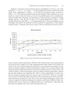
Figure 23. a) Distance and orientation measuring with three laser beams and
a Position Sensitive Detector. b) Prototype of the Opto3D measuring head.
1
Ammamcy
?
/
L.uNr, :?
tm~r2 -~
-,- Uumr 3 ,*
.,i'/
./
I~ Z [ram)
On~nRa~
en'~
(par~l~ ~4~rfac~z)
ErmcX /
ErrorY
,11"
1~ 2OO 3C~ 4OO SO0
CHslanceZ[mm]
J
I
//
I I
.J
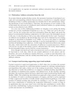
Figure 24. a) Distance accuracy vs. range, b) Angular accuracy for a perpen-
dicular surface.
otherwise it is enough to detect its presence. The main problems of triangula-
tion systems are the possibility of occlusion, and measures on specular surfaces
that can blind the sensor or give rise to wrong measures because of multiple
reflections [53, 54, 55, 56, 57, 58].
Opto3D
The Opto3D system is a triangulation sensor that uses a PSD 4 camera and
three laser beams. Measuring the coordinates of the three intersection points
P1, P2 and P3 (see Figure 23a), the sensor can calculate the orientation ~ of
the surface by the following expression:
= PI"P~ x Pl"Pa
(16)
The Opto3D sensor can measure distances up to 75
cm
with accuracies
from 0.05 to 2
mm
(see Figure 24) [54, 53]. Like every triangulation sensor, the
4position Sensitive Detector
7'7
Zl z 2 z 3
f ~
I z
Figure 25. Using the Gauss lens law, it is possible to extract range information
from the effective focal distance of an image.
accuracy degrades with the distance. This sensor can measure orientation on a
broad range with an accuracy better than 0.1 °, and the maximum orientation
depends on the reflective properties of the surface (usually only a little amount
of light can be detected from light beams that follow over almost tangential
surfaces).
6.2.4. Lens Focusing
Focus range sensing relies on Gauss thin lens law (equation 17). If the focal
distance (f) of a lens and the actual distance between the focused image plane;
and the lens center (re) is known, the distance (z) between the lens and the,
imaged object can be calculated using the following equation:
1 1 1
-
(17)
f
z
The main techniques exploring this law are range from focus (adjust
the focal distance fe till the image is on best focus) and range from defocus
(determine range from image blur).
These techniques require high frequency textures, otherwise a focused im-
age will look similar to a defocused one. To have some accuracy, it is fundamen-
tal to have very precise mathematical models of the image formation process
and very precise imaging systems [59].
Image blurring can be caused by the image process or by the scene itself,
so depth from defocus technique, requires the processing of at least two images
of an object (which may or may not be focused) acquired with different but
known camera parameters to determine the depth. A recent system provides
the required high-frequency texture projecting an illumination pattern via the
same optical path used to acquire the images. This system provide real-time
(30 Hz) depth images (512 x 480) with an accuracy of approximately 0.2% [60].
The accuracy of focus range systems is usually worse than stereoscopic
ones. Depth from focus systems have a typical accuracy of 1/1000 and depth
from defocus systems 1/200 [59]. The main advantage these methods is the
lack of correspondence problem (feature matching).
78
7.
Conclusions
The article described several sensor technologies, which allow an improved esti-
mation of the robot position as well as measurements about the robot surround-
ings by range sensing. Navigation plays an important role in
all
mobile robot
activities and tasks. The integration of inertial systems with other sensors in
autonomous systems opens a new field for the development of a substantial
number of applications. Range sensors make possible to reconstruct the struc-
ture of the environment, avoid static and dynamic obstacles, build maps and
find landmarks.
References
[1] Altschuler M, et al. 1962 Introduction. In: Pitman G R (ed), Inertial Guidance,
John Wiley & Sons, pp 1-15
[2] Feng L, Borenstein J, Everett H December 1994 Where am I? - Sensors and
Methods for Autonomous Mobile Robot Positioning. Tech. Rep. UM-MEAM-
94-21, University of Michigan
[3] Everett H 1995 Sensors for Mobile Robotics. A.K. Peters, ISBN 1-56881-048-2
[4] Vi~ville T, Faugeras O 1989 Computation of Inertial Information on a Robot. In:
Miura H, Arimoto S (eds), Fifth International Symposium on Robotics Research,
MIT-Press, pp 57-65
[5] Collinson R 1996 Introduction to Avionics. Chapman & Hall, ISBN 0-412-48250-
9
[6] Ausman J S 1962 Theory o] Inertial Sensing Devices, George R. Pitman (ed.),
John Wiley & Sons, pp 72-91
[7] Slater J M 1962 Principles o] Operation of Inertial Sensing Devices, George R.
Pitman (ed.), John Wiley & Sons, pp 47-71
[8] Kuritsky M M, Goldstein M S 1990 Inertial Navigation, T. Lozano-Perez (ed),
Springer-Verlag New York, pp 96-116
[9] Allen H V, Terry S C, Knutti J W September 1989 Understanding Silicon Ac-
celerometers. Sensors
[10] ICSensors January 1988 Silicon Accelerometers. Technical Note TN-008
[11] Summit Instruments September 1994 34100A Theory of Operation. Technical
Note 402
[12] Barshan B, Durrant-Whyte H June 1995 Inertial Navigation Systems for Mobile
Robots. IEEE Transactions on Robotics and Automation, 11:328-342
[13] Komoriya K, Oyama E 1994 Position Estimation of a Mobile Robot Using Op-
tical Fiber Gyroscope (OFG). In: Proceedings of the 1994 IEEE International
Con]erence on Intelligent Robots and Systems, pp 143-149
[14] Murata 1991 Piezoelectric Vibrating Gyroscope GYROSTAR. Cat. No. $34E-1
[15] Systron Donner Inertial Division 1995 GyroChip. Product Literature
[16] Peters T May 1986 Automobile Navigation Using a Magnetic Flux-Gate Com-
pass. IEEE Transactions on Vehicular Technology, 35:41-47
[17] KVH Industries, Inc May 1993 C100 Compass Engine Technical Manual. Revi-
sion g edn., KVH Part No. 54-0044
[18] Getting I A December 1993 The Global Positioning System. IEEE Spectrum, pp
236-247
[19] Kaplan E D 1996 Understanding GPS: Principles and Applications. Artech
House, ISBN 0-89006-793-7
79
[20] Kelly A May 1994 Modern Inertial and Satellite Navigation Systems. Tech. Rep.
CMU-RI-TR-94-15, Carnegie Mellon University
[21] Dana P H 1997 Global Positioning System Overview. Tech. Rep. CMU-
RI-TR-94-15, Department of Geography, University of Texas at Austin,
http: / /www.utexas.edu / depts / grg/ gcraft /notes/ gps / gps.html
[22] Carpenter H 1988 Movements of the Eyes. London Pion Limited, 2nd edn., ISBN
0-85086-109-8
[23] Lobo J, Lucas P, Dias J, de Almeida A T July 1995 Inertial Navigation Sys-
tem for Mobile Land Vehicles. In: Proceedings o/the 1995 IEEE International
Symposium on Industrial Electronics, Athens, Greece, pp 843-848
[24] Dias J, Paredes C, Fonseca I, de Almeida A T 1995 Simulating Pursuit wit]h
Machines. In: Proceedings of the 1995 IEEE Conference on Robotics and Au-
tomation, Japan, pp 472-477
[25] Paredes C, Dias J, de Almeida A T September 1996 Detecting Movements Using
Fixation. In: Proceedings of the 2nd Portuguese Conference on Automation and
Control, Oporto, Portugal, pp 741-746
[26] Smith S, Brady J May 1997 SUSAN - a new approach to low level image pro-
cessing. Int Journal of Computer Vision, pp 45-78
[27] Silva A, Menezes P, Dias J 1997 Avoiding Obstacles Using a Connectionist Net-
work. In: Proceedings of the 1997 IEEE International Conference on Intelligent
Robots and Systems (IROS'97), pp 1236-1242
[28] Besl P 1988 Active Optical Range Imaging Sensors. Machine Vision and Appli-
cations, 1:127-152
[29] Jarvis R March 1983 A perspective on Range Finding Techniques for Computer
Vision. IEEE Trans Pattern Analysis and Machine Intelligence, PAMI-5:122
139
[30] Volpe R, Ivlev R 1994 A Survey and ExperimentM Evaluation of Proximity'
Sensors for Space Robotics. In: Proc. IEEE Conf. on Robotics and Automation,
pp 3466-3473
[31] Phong B June 1975 Illumination for computer generated pictures. Commun o/
the ACM, 18:311-317
[32] Marques L, Castro D, Nunes U, de Almeida A 1996 Optoelectronic Proxim-
ity Sensor for Robotics Applications. In: Proc. 1EEE 8'th Mediterranean Elec-
trotechnical Conf., pp 1351-1354
[33] Flynn A 1985 Redundant Sensors for Mobile Robot Navigation. Tech. Rep. 859,
MIT Artificial Intelligence Laboratory
[34] Flynn A December 1988 Combining Sonar and Infrared Sensors for Mobile Robot
Navigation. International Journal of Robotics Research, 7:5-14
[35] Duds R, Nitzan D, Barret P July 1979 Use of Range and Reflectance Data
to Find Planar Surface Regions. IEEE Trans Pattern Analysis and Machine
Intelligence, PAMI-l:259-271
[36] Nitzan D, Brain A, Duds R February 1977 The Measurement and Use of Regis-
tered Reflectance and Range Data in Scene Analysis. Proceedings of the 1EEE,
65:206-220
[37] Jaxvis R September 1983 A Laser Time-of-Flight Range Scanner for Robotic
Vision. 1EEE Trans Pattern Analysis and Machine Intelligence, PAMI-5:505-
512
[38] Carmer D, Peterson L February 1996 Laser Radar in Robotics. Proceedings of
the 1EEE, 84:299-320
80
[39] Conrad D, Sampson R 1990 3D Range Imaging Sensors. In: Henderson T (ed),
Traditional and Non-Traditional Robotic Sensors, Springer-Verlag, Berlin, vol.
F63 of NATO ASI Series, pp 35-48
[40] Will P, Pennington K June 1972 Grid Coding: A Novel Technique for Image
Processing. Proceedings of the IEEE, 60:669-680
[41] Stockman G, Chen S, Hu G, Shrikhande N June 1988 Sensing and Recognition of
Rigid Objects Using Structured Light. IEEE Control Systems Magazine, 8:14-22
[42] Dunn S, Keizer R, Yu J November 1989 Measuring the Area and Volume of the
Human Body with Structured Light. IEEE Trans Systems Man and Cybernetics,
SMC-19:1350-1364
[43] Wang Y, Mitiche A, Aggarwal J January 1987 Computation of Surface Orienta-
tion and Structure of Objects Using Grid Coding. IEEE Trans Pattern Analysis
and Machine Intelligence, PAMI-9:129-137
[44] Wang Y January 1991 Characterizing Three-Dimensional Surface Structures
from Visual Images. IEEE Trans Pattern Analysis and Machine Intelligence,
PAMI-13:52-60
[45] Altschuler M, et al. 1987 Robot Vision by Encoded Light Beams. In: Kanade T
(ed), Three-dimensional machine vision, Khwer Academic Publishers, Boston,
pp 97-149
[46] Vuylsteke P, Oosterlinck A Feb 1990 Range Image Acquisitionwith a Single
Binary-Encoded Light Pattern. IEEE Trans Pattern Analysis and Machine In-
telligence, PAMI-12:148-164
[47] Kak A, Boyer K, Safranek R, Yang H 1986 Knowledge-Based Stereo and Struc-
tured Light for 3-D Robot Vision. In: Rosenfeld A (ed), Techniques for 3-D
Machine Perception, Elsevier Science Publishers, pp 185-218
[48] Boyer K, Kak A January 1987 Color-Encoded Structured Light for Rapid Active
Ranging. IEEE Trans Pattern Analysis and Machine Intelligence, PAMI-9:14-28
[49] Wust C, Capson D 1991 Surface Profile Measurement Using Color Frinje Pro-
jection. Machine Vision and Applications, 4:193-203
[50] Maruyama, Abe S Jun 1993 Range Sensing by Projecting Multiple Slits with
Random Cuts. IEEE Trans Pattern Analysis and Machine Intelligence, PAMI-
15:647-651
[51] Vuylsteke P, Price C, Oosterlinck A 1990 Image Sensors for Real-Time 3D Acqui-
sition: Part 1. In: Henderson T (ed), Traditional and Non-Traditional Robotic
Sensors, Springer-Verlag, Berlin, vol. F63 of NATO ASI Series, pp 187-210
[52] Mouaddib E, Battle J, Salvi J 1997 Recent Progress in Structured Light in order
to Solve the Correspondence Problem in Stereo Vision. In: Proc. IEEE Conf.
on Robotics and Automation, pp 130-136
[53] Marques L 1997 Desenvolvimento de Sensores Optoelectr6nicos para AplicaqSes
de Rob6tica. Master's thesis, DEE, FCT - Universidade de Coimbra
[54] Marques L, Moita F, Nunes U, de Almeida A 1994 3D Laser-Based Sensor for
Robotics. In: Proc. IEEE 7'th Mediterranean Electro. Conf., pp 1328-1331
[55] Lee S 1992 Distributed Optical Proximity Sensor System: HexEYE. In: Proc.
IEEE Conf. on Robotics and Automation, pp 1567-1572
[56] Lee S, Desai J 1995 Implementation and Evaluation of HexEYE: A Distributed
Optical Proximity Sensor System. In: Proc. IEEE Conf. on Robotics and Au-
tomation, pp 2353-2360
[57] Kanade T, Sommer T 1983 An Optical Proximity Sensor for Measuring Surface
Position and Orientation for Robot Manipulation. In: Proc. 3rd International
131
Conference on Robot Vision and Sensory Controls, pp 667-674
[58] Kanade T, Fuhrman M 1987 A Noncontact Optical Proximity Sensor for Mea-
suring Surface Shape. In: Kanade T (ed), Three-dimensional machine vision,
Kluwer Academic Publishers, Boston, pp 151-192
[59] Xiong Y, Sharer S A 1993 Depth from Focusing and Defocusing. Tech. Rep.
93-07, The Robotics Institute - Carnegie Mellon University
[60] Nayar S, Watanabe M, Noguchi M Dec 1996 Real-Time Focus Range Sensor.
IEEE Trans Pattern Analysis and Machine Intelligence, PAMI-18:l186-1198
Application of Odor Sensors in Mobile
Robotics
Lino Marques and Anibal T. de Almeida
Institute of Systems and Robotics
Department of Electrical Engineering - University of Coimbra
3030 Coimbra, Portugal
{lino, adealmeida} @isr.uc.pt
Abstract:
Animals that have a rather small number of neurons, like insects, display a
diversity of instinctive behaviours strictly correlated with particular sensory
information. The diversity of behaviors observed in insects has been shaped
by millions of years of biological evolution, so that their strategies must be
efficient and adaptive to circumstances which change every moment. Many
insects use olfaction as a navigation aid for some vital tasks as searching
for sources of food, a sexual partner or a good place for oviposition.
This paper discusses the utilisation of olfaetive information as a navigational
aid in mobile robots. The main technologies used for chemical sensing and
their current utilisation on robotics is presented. The article concludes
giving clues for potential utilisation of electronic noses associated to mobile
robots.
1. Introduction
Although it is rather common to find robots with sensors that mimic the ani-
mal world (particularly the man senses), sensors for taste and smell (chemical
sensors) are by far the least found on robotics. The reasons for that are not
just the reduced importance of those senses in human motion, but it is also a
consequence of the long way for chemical sensors to evolve in order to become
similar to their biological counterparts.
Traditional systems for analysis of the gases concentration in the air were
bulky, fragile and extremely expensive (spectroscopic systems). The least ex-
pensive options based on catalytic or metal oxide sensors had little accuracy,
reduced selectivity and short lifetime. Several recent advances in these tech-
nologies and the development of new ones, like conducting polymers and optical
fibres, lead to the appearance of a new generation of miniature and low cost
chemical sensors that can be used to build small and inexpensive electronic
noses.
Robots can take advantage from an electronic nose when they need to
carry out some chemically related tasks, such as cleaning and finding gas leaks,
or when they want to implement a set of animal-like instinctive behaviors based
on olfactive sensing.
83
(~) (b) (¢)
Figure 1. There are several animal behaviors based on olfactory sensing that
can be implemented on mobile robots, namelly the following: (a) Repellent
behaviors, where a robot goes away from an odor. This behavior can be used
on a cleaning robot to detect the pavement already cleaned. (b, c) Attractive
behaviors, where a robot can follow a chemical trail or find an odor source.
There are several animal behaviors based on olfactory sensing that can be
implemented on mobile robots. Among those behaviors we can emphasize:
1. Find the source of an odor (several animals).
2. Lay down a track to find the way back (ants).
3. Go away from an odor (honeybees).
4. Mark zones of influence with odors.
Small animals, like some insects, can successfully move in changing un
structured environments, thanks to a set of simple instinctive behaviors based
on chemically sensed information. Those behaviors, although simple, are very
effective because they result from millions of years of biological evolution.
There are two chemically related strategies that can be used for mobile
robotics navigation. The searching strategy, where the robot looks for an odor
source or a chemical trail, and the repellent strategy, where the robot goes
away from an odor.
Insects frequently use the first strategy when they look for food or for eL
sexual partner. For example, when a male silkworm moth detects the odor
liberated by a receptive female it starts a zigzagging search algorithm until it
finds the odor source [1, 2].
Ants establish and maintain an odor trail between the source of food and[
their nest. All that they have to do in order to move the food to the nest, is
to follow the laid chemical trail [3].
The second strategy, to go away from a specific odor, is used by several
animals to mark their territory with odors in order to keep other animals away
84
Honeybees also use this strategy, but to improve their efficiency when gathering
nectar. They mark the visited flowers with an odor that remains active while
the flower creates more nectar. This way they do not need to land on flowers
that have no nectar.
Although simple, these kinds of behaviors were successfully used on nature
during millions of years. Its implementation on mobile robots can improve
their performance without the need for heavy control algorithms. For example,
a cleaning robot can use chemical sensorial information to know when a floor
is already cleaned (see Figure ia). A security robot can mark its path with
a volatile chemical in order to know when it has recently passed somewhere.
In this way, a set of security robots can co-operatively patrol an area without
centralised control among them.
When large amounts of material must be transferred from a place to an-
other, an intelligent mobile robot can be used to mark the path with a chemical
mark while simple AGV-like transport robots equipped with chemical sensors
can follow that path (see Figure lb).
Hydrogen is among the most widely used gases in industry. A 1995 NASA
report refers that undetected leaks are the largest cause of industrial hydrogen
accidents. A robot with a sensitive electronic nose could be used to patrol
industrial plants and report any abnormal gas concentration on the air. These
reports could be a good help for the factory maintenance staff to discover leaks,
to detect fires or overheated equipment, and damaged stored material. Such a
robot could even use the nose information as a localisation instrument. Usually
there are places with typical odors, that could be used as landmarks.
2. Chemical gas sensors
The increasing need for control of industrial processes and environment mon-
itoring, pushed the research in new chemical sensing technologies. The main
gas categories to be monitored in common applications are:
1. Oxygen, for the control of combustion processes.
2. Flammable gases in order to protect against fire or explosion.
3. Toxic gases for environmental monitoring.
This section presents several kinds of sensors that can be used to detect
chemical gases in the environment. Some more detailed surveys can be found
in the references [4, 5, 6, 7, 8, 9, 10].
2.1. Solyd electrolyte sensors
As voltaic cells, solyd electrolyte sensors are based on the voltage generated in
the interface between phases having different concentrations.
These sensors have three components, two metallic electrodes (one of which
coated with a catalyst), an electrolyte and a membrane. When an electroac-
tive gas diffuses through the membrane and reacts at the electrolyte-catalyst
interface, it generates a current proportional to the gas concentration.
85
These sensors can detect gases in the
ppm
range, but their lifetime depends
on the exposition to the reacting gas. Millions of vehicles in the entire world
use this type of sensor to monitor the exhausted gases and minimize the toxic
emissions.
2.2. Thermal-chemical sensors
Thermal-chemical sensors detect the heat released or absorbed,
AEh,
when eL
reaction takes place. This change in enthalpy causes a change in temperature,
AT, which can be monitored. In the ideal case the system should be thermally
isolated. In practice there are heat losses through convection, conduction and
radiation, that affect the detected temperature change [11]. The main applica-
tion of these sensors is the monitoring of combustible gases.
The pellistor is the most common thermal-chemical sensor (other thermal[
sensors are based on either on thermistors or on thermopiles). This sensor is
composed by a platinum coil buried in a probe covered with a thin catalytic
layer. The coil serves to heat the sensor to its operating temperature (about
500°C) and to detect the increase in temperature from the reaction with the
gas. The coil resistance changes about 0.4%/°C.
Pellistors are produced since the early 70's. They have a low price, but
they feature high power dissipation (about 1 W), non-selective response, drift
and sensitivity to humidity and temperature. These devices can be irreversibly
poisoned by some contaminant vapors that shorten their life.
2.3. Gravimetric chemical sensors
When a chemical species interacts with the sensing material, it often results in
a change in the total mass. This small change in mass can be measured by a
microbalance using either a piezoelectric Bulk Acoustic Wave (BAW) oscillator
or a Surface Acoustic Wave (SAW) device. These devices are composed by
a peace of piezoelectric material (usually Quartz) coated with a thin film of a
chemically selective absorbent material [12].
In these sensors the change in mass Am is converted to a frequency shift
Af by an oscillator circuit.
af = k. Am (1)
Where k is a constant. The performance of the chemical sensor depends on
the frequency of operation and on the functionality of the chemically-sensitive
coating.
SAW devices generally work at much higher frequencies than BAW devices,
so for the same sensitivity, they can be made much smaller and less expensive.
SAW sensors are also very attractive for the development of sensor arrays be-
cause this technology can be applied on two-dimensionM structures [5]. These
sensors can have a mass resolution down to 1
pgram.
2.4. Conducting polymers
Conducting polymers are plastics that change its electrical resistance as they
adsorb or desorb specific chemicals. The adsorption of volatile chemicals de-
pends on their polarity (charge) and spatial geometry of the material micro-
structure (size and shape). The better the fit, the greater the electrical change.
86
An elevated concentration of a poorly fitting chemical can have the same effect
as a low concentration of a good fitting chemical [13, 14].
Conducting polymers are relatively new materials on chemical sensing
(they appeared in the early 80's), but because of their good qualities (namely:
excellent sensitivity - down to some
ppb,
low price and rapid response time at
room temperatures), they have the potential to become the dominant chemical
gas sensing technology in the near future.
2.5. IR spectroscopy
Because of their natural molecular vibration, all gases interfere and absorb light
at specific wavelengths of the infrared spectrum. This property can be used to
detect the concentration of different gases in the environment.
There are monochromatic systems tuned with narrow-band interference
filters or laser light sources for a specific gas (like
C02)
and there are spectro-
scopic systems able to determine the concentration of several gases at once.
These sensors feature slow response, good linearity, low cross-sensitivity
to other gases and fairly good accuracy, but they need frequent recalibration,
are bulky and very expensive.
2.6. Optical fiber sensors
Optical fiber gas sensors are composed by a fiber bundle with its ends coated
with a gas-sensitive fluorescent polymer. When light comes down the fiber, it
excites the polymer, which emits at a longer wavelength to the detection system.
The amount of returning fluorescent light is related with the concentration of
the chemical species of interest at the fiber tips.
Tufts University uses an array of 19 fibers coated with Nile Red dye. To
differentiate among various chemical gases, they correlate the amount of re-
turned intensity and the fluorescence lifetime in each fiber [15].
2.7. Metal oxide sensors (MOS)
The adsorption of a gas onto the surface of a semiconducting material can
produce a large change in its electrical resistivity. Although this effect was
observed since the early 1950s, the non-reproducibility of the results was a
major problem and the first commercial devices were only produced in 1968 [16,
17].
The most common metal oxide gas sensor is the Tagushi type. This sensor
uses a thin layer of powder tin oxide
(Sn02).
When the sensor is heated at
a high temperature (usually 300 to 450°C), some oxygen molecules from the
air are adsorbed on the crystal surface and remove electrons from the
Sn02
grains (see Figure 2a). Because tin oxide is a type n semiconducting material,
this process reduces the charge carrier density, increasing the grain-to-grain
contact resistance and consequently increasing the electrical resistivity of the
sensor. In the presence of a deoxidizing gas, the reducing reaction decreases the
concentration of oxygen molecules in the crystal (see Figure 2b). This effect
can be detected by a decrease in the sensor resistance. Typically, a reducing
gas concentration of 100
ppm
can change the resistance of the sensor by a factor
of 10.
87
• Electron
Grain
bou
• Electron
Reducing
gas
in the
presence
-e of
reducing gas
t~
(~) (b)
Figure 2. a) Model of inter-grain potential barrier in the absence of gases, b)
Model of inter-grain potential barrier in the presence of gases (adapted from
Figaro data sheets).
The relationship between sensor resistance and the concentration of the
deoxidizing gas can be expressed by the following equation:
R = R0(1 + A.C) -~
(2)
Where R is resistance of the sensor in the presence of the gas, R0 is the
resistance in the air, A and ~ are constants and C is the concentration of the
deoxidizing gas [18].
MOS sensors are simple and inexpensive gas sensitive resistors that can be
used to detect a wide range of reducing gases. The sensitivity of each sensor
to a gas depends on the oxide material, on its temperature, on the catalytic
properties of the surface and on the humidity and oxygen concentration in
the environment. The most common used material is tin oxide, but some
researchers are trying other oxides (for example
Ga~03) with better stability,
reproducibility, selectivity and insensitivity to environmental conditions [19,
20].
3.
Electronic noses
Almost all the sensors described in the previous section suffer from some prob-
lems; the main ones are lack of selectivity and the inability to give the concen-
tration of gas components. To overcome these problems, Dodd and Persaud
proposed a device that tries to mimic the mammalian olfactory system [21].
This device, which they called electronic nose, incorporated three broadly-
tuned tin oxide gas sensors and used pattern recognition algorithms to discrim-
inate between chemically similar odors.
The two main components of an electronic nose are the chemical sensing
88
Gas sample
Array of weakly
selective sensors
Pattern
recognition
algorithm
Results
~
_x pp._ mm of A ]
y ppm of B
"~ z ppm of C
Electronic Nose
Figure 3. Representation of an electronic nose.
system and the pattern recognition system (see Figure 3). The sensing system
is composed by a chemical sensor array, where each element measures a different
property of the sensed gas. In this way each vapor presented to the sensing
system produces a characteristic signature. The goal of the pattern recognition
algorithm is to identify each component of the sensed gas based on the signals
from each sensing element [22, 23, 24].
To operate properly, the electronic nose should first be calibrated. In the
calibration process the system is placed inside a controllable and isolated envi-
ronment, and its response is measured for different and known concentrations
of the products to be detected.
There are two common methods used to control the concentration of the
volatile products inside the isolated recipient. The static method, where
a fixed volume of the product is injected inside the recipient [25], and the
mass flow method where a constant flow of a carrier gas with the sample
product circulates through the recipient [26, 27, 28, 29, 30, 31]. In the first
case the product concentration inside the recipient can be calculated through
the injected volume and the volume of the recipient. The second method needs
mass flow controllers to mix the sample product in the carrier gas. The main
advantage of this method is its velocity.
3.1. Sensor arrays
There are now more then ten companies selling electronic noses. The sensing
technologies chosen by almost all of them are a combination of conductive
polymers, MOS sensors or piezoelectric elements. In research institutions other
sensing technologies like MOSFET chemical sensors and fluorescent polymers
associated with optical fibers are also found [32, 15].
Conductive polymers and MOS sensors are simpler to interface because
they are resistive elements. Piezoelectric elements need more complicated signal
conditioning circuits to convert the frequency to a voltage. It is also common
in this case to compensate the frequency drift due to temperature effects with
a non-exposed sensing element.
Figure 4 presents the diagram of a typical olfactory sensing system based
heating
control
~ Gas
sensor
array
fan
(~ temperature sensor
(~ humidity sensor
Figure 4. Diagram of a MOS based olfactory sensing system.
89
Figure 5. Prototype of the ISR electronic nose. The nose is composed by an
array of 11 Tagushi gas sensors, a humidity sensor and a temperature sensor.
The gas analysis is based on a fuzzy neural network approach.
on MOS elements. The non-linear dependence of the sensor resistance with the
heating temperature can be used to increase the dimension of the data array.
This way, for each temperature of the sensors there are linearly independent
sets of values. Because MOS gas sensors feature also a high sensitivity to
environment humidity and temperature, it is common to feed these variables
to the pattern recognition algorithm.
Figure 5 presents a board with several commercial MOS sensors. The
resistance change of each element when the array is exposed to alcohol can be
seen in Figure 6. Before the sensor output is fed to the pattern recognition
algorithm, these values should be pre-processed. Some typical pre-processing
methods use the difference between the resistance in air and in gas
Rai,. -
Rgas
[33]. Other methods use the relative value
(Rgas)/Rair ,
the relative
difference
(Ra~r - Rga,)/Rai,.,
or the logarithm of these relations [18, 33, 34].
90
R(k~)
Alcohol
exposure
TGS813
TGS880
TGS2611
TGS2610
TGS2620
0 20 40 60 80 100 120 140 160 180 s
Figure 6. Output from a MOS sensor array to an alcohol exposure. It is
visible the low selectivity of each element. The elements in a top down order
are the Figaro TGS813, TGS880, TGS2611, TGS2610, TGS2620, TGS822 and
TGSS00
3.2. Pattern recognition
The number of identifiable patterns from a sensor array is limited by the number
of different gas sensors, by their repeatability, by the quantization errors on the
acquired signals, and by the calibration accuracy.
There are two conventional methods for extracting information about the
gas mixture composition from multiple sensors: one is a statistical technique
such as multiple linear regression, and the other is based on artificial neural
networks (ANN) [35, 36].
The first pattern recognition methods used on electronic noses were based
on vector space methods [37]. These methods model the sensor output as a
linear combination of exposed gas's concentration:
Vn = alnC1 + a2nC2 + q- am,~Cm
(3)
where Vn is the output of sensor n, C1 to
Crn
is the concentration of each
constituent gas and al~ to a,~ are linear constants to be determined by cal-
ibration. For simplicity we can write the equation of each sensor on a matrix
format:
V = A. C (4)
Before using the system we should determine the elements of A. These are
obtained by exposing the system to known samples of calibration gases.
A = V. C -1 (5)
When a gas is to be tested, then a set of simultaneous equations is obtained
and solved to give the value of concentration for each constituent gas.
!)1
C=A -1 .V
(6)
The main problems with this model are the non-linearity of the sensor
elements (see for example equation 2 for the case of MOS elements), limitations
on the signal accuracy, difficulties of calibration, and the possible presence of
additional constituents at a significant level.
More recent approaches are based on ANN. Many ANN configurations
and training algorithms have been used to build electronic noses including:
backpropagation-trained, multilayer feed-forward networks, fuzzy ARTmaps,
learning vector quantizers (LVQs), Hamming networks, etc [25, 38, 39, 31, 35,
40, 41, 42].
4. Current utilization of odor sensing in robotics
Several authors have suggested the utilization of chemical sensing on mobile
rol~otics. Engelberger for example suggested the utilization of a short-lived
chemical mark as an aid for floor cleaning robots [43]. Siegel imagined sce-
narios for mobile robots self-directed motivation based on chemical senses. He
supported his theory on the chemically based navigation of primitive mobile
life forms [44, 45].
Russell investigated the use of an odor as a temporal navigational marker.
He followed a camphor trail with a mobile robot equipped with two piezoelectric
gas sensors. In the beginning the robot was placed with a sensor on the left
side of the trail and the other sensor on the right side. The main problems
reported by the author are related to the time response of the sensor and the
uncertain duration of the mark [46, 47].
Kanzaki and Ishida proposed some odor-source searching strategies with-
out memory and learning, based on the silkworm moth behavior [1, 2]. In their
experiences, they used a mobile stage with four pairs of gas and anemometric
sensors. They disposed the sensors apart from each other, so that they could
measure gas concentration gradients and wind direction. From the experiences
carried out, they found out that if the stage is already inside an odor plume
and the wind is strong enough, they could move upward the gradient to find
the odor-source. Otherwise, it was better to zigzag obliquely upwind across
the plume in order to find the odor-source [48, 49].
Cybermotion is an US enterprise that builds security robots equipped with
a set of environmental monitoring sensors. Among those sensors there are
temperature, humidity, smoke, flame and MOS gas sensors for detection of
explosive and toxic gases. With these sensors the robot is able to perform a
set of preventive tasks that have already made possible the detection of toxic
gases, gas leaks, burning equipment, etc.
5. Future developments and expected utilization
This section identifies some applications of electronic noses associated to mobile
robots.
92
5.1. Security
One of the best tools for narcotics and explosive detection is the dog. It is
believed that an Alsatian dog can detect TNT in concentrations as low as five
parts per billion.
A robot with a very sensitive electronic nose that detects dangerous (ex-
plosives) and illegal substances (drugs) and can be an excellent replacement for
police dogs. This robot could be used to patrol public buildings like embassies,
airports, train stations, etc. It can move with autonomy, does not become tired
and does not need special training.
5.2. Demining
The number of abandoned land mines was estimated to exceed 100 million
spread by over 67 countries. At present, it costs about $3 dollars to lay a mine
and from $200 to $1000 to find it again and dig it up. For every dug mine,
up to 20 more are laid. For example in Angola, there are more mines in the
ground than people in the country.
A possible solution for the problem is the development of an autonomous
robot that could be placed on the ground to demine dangerous areas [50]. The
biggest problem with such a robot is the lack of good sensors for mine detection.
Since World War II land mines are essentially plastic, having a minimal metal
content. The only way to sense such a mine is to detect the explosive vapors
liberated by them. Although it is a difficult task, there are numerous research
groups searching for a suitable sensor to detect these mines with some good
results already reported [51, 52].
5.3. Agriculture
In recent years several research groups have study the application of robotics
in agriculture. The automation of tasks like measurement and control of envi-
ronmental conditions, plant inspection, and spraying of pesticides, fungicides
and other chemical products over the plants, can have significant economic
and health impacts, avoiding the workers exposure to insecticides and other
dangerous chemical products [53].
Electronic noses have plenty of potential usefulness associated with farming
robots, because they provide the necessary sensorial feedback for some of the
most common farming tasks. For example the robot can analyze in real-time
the volatile compounds released by the soil and fertilize it with the estimated
needs. This way the fertilizer is not wasted and the soil does not become
contaminated with too much nitrate.
The electronic nose can analyze the environmental conditions to prevent
diseases and actuate before the plants become ill. Some diseases release volatile
compounds. In these cases, if the plants are already ill, the robot can report
the situation in order to prevent the spread of the disease.
A harvesting robot can use aroma information to selectively gather ripe
fruits or adult flowers. If the robot knows a map of the plants around the
farm, it can use odor information as a rough localization method: near a rose
flowerbed, it should smell rose aroma.
93
5.4. Environmental monitoring
A robot with an electronic nose patrolling a commercial building or an indus
trial plant, can identify contaminants in the field and make real-time reports,
about the environmental state. When the robot finds some abnormal situation:,
like a gas leak or an equipment on fire, it can place a warning for the plant
control.
5.5. Cleaning
A cleaning robot with an electronic nose can detect the ammonia odor of an
already cleaned floor. This way the robot does not waste time cleaning the
floor again.
5.6. Cooperative robotics
Volatile chemicals can be used as temporary marks to coordinate a set of au-
tonomous robots executing a common task [54]. For example, if several cleaning
rob'ots clean a huge area, they can use odor information to detect places re-
cently cleaned by other robots because the ammonia odor will be stronger in
these places. In a similar way, security robots can mark its path with a volatile
trail in order to detect paths recently patrolled.
References
[1] Kanzaki R 1996 Behavioral and neural basis of instictive behavior in insects:
Odor-source searching strategies without memory and learning. Robotics and
Autonomous Systems, 18:33-43
[2] Ishida H, Hayashi H, Takakusaki M, Nakamoto T, Moriizumi T, Kanzaki R
1996 Odour-source localization system mimicking behaviour of silkworm moth.
Sensors and Actuators, A99:225-230
[3] Sudd J 1967 An Introduction to the Behavior of Ants. Arnold Publishers
[4] Moseley P 1997 Solid state gas sensors. Measurement Science and Technology,
8:223-237
[5] Gardner J 1994 Microsensors, Principles and Applications. John Wiley &: Sons
[6] GSpel W, Jones T, Kleitz M, Lundstrom J, Seiyama T (eds) 1991 Sensors: A
Comprehensive Survey, vol. 2. Weinheim: VCH
[7] GSpel W, Jones T, Kleitz M, Lundstrom J, Seiyama T (eds) 1992 Sensors: A
Comprehensive Survey, vol. 3. Weinheim: VCH
[8] Moseley P, Tofield B (eds) 1987 Solid State Gas Sensors. Adam Hilger
[9] Moseley P, Norris J, Williams D (eds) 1991 Techniques and Mechanisms in Gas
Sensing. Adam Hilger
[10] Lambrechts M, Sansen W (eds) 1992 Biosensors: Microelectrochemical Devices.
Adam Hilger
[11] Jones E 1987 The Pellistor Catalytic Gas Detector. In: Moseley P, Tofield B
(eds), Solid State Gas Sensors, Adam Hilger, pp 17-31
[12] Nieuwenhuizen M, Nederlof A 1992 Silicon Based Surface Acoustic Wave Gas
Sensors. In: Gardner J, Bartlett P (eds), Sensors and Sensory Systems for an
Electronic Nose, Kluwer Academic Publisher, vol. E212 of NATO ASI Series,
pp 131-145
[13] Bartlett P, Archer P, Ling-Chung S 1989 Conducting polymer gas sensors, Part I:
Fabrication and characterization. Sensors and Actuators, 19:125-140