Build A Remote-Controlled Robot Part 4 doc
Bạn đang xem bản rút gọn của tài liệu. Xem và tải ngay bản đầy đủ của tài liệu tại đây (173.86 KB, 10 trang )
xxx
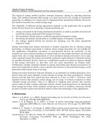
FIGURE I-21.
Can you name this robot? (
Courtesy of American Robots.)
xxxi
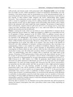
FIGURE I-22.
Does this alternate head design look familiar? (
Courtesy of American Robots.)
This page intentionally left blank.
THE MOTORIZED
PLATFORM
T
he motorized platform is a most important part of
Questor’s construction. It not only supplies the robot with
mobility, but contributes to its personality and appeal.
Although simple in construction, the platform outlined in this
chapter is capable of carrying 50 pounds of robot. To start its
construction, the first job to perform is to prepare the motor-
ized wheels that propel the platform.
PREPARING MOTORIZED WHEELS
Once you have obtained the motorized wheels, study them
and learn how they operate and how they are assembled. This
is important because you must disassemble the wheels in
order to prepare them for attachment to the platform. Be
careful not to lose any of the smaller parts and work on only
one wheel at a time. Figures 1-1 and 1-2 show an assembled
and disassembled wheel.
To disassemble the wheel, first remove the motor and gear-
box assembly held to the side of the wheel’s frame by three
small screws. On the opposite side of the frame is a cotter pin
that holds the wheel’s axle and frame together. Remove this
pin (this is done easily with a pair of needle nose pliers) and
pull the axle out from the other side slowly. As you pull the
axle out, four small spacing washers, two red plastic and two
metal, will fall from the frame along with the wheel itself and
the wheel’s large white driver gear.
1
CHAPTER
ONE
Copyright 2002 The McGraw-Hill Companies, Inc. Click Here for Terms of Use.
Next remove the swivel ring from the top of the now bare
frame. The ring is held in place by a cotter pin that passes
through the large post on the top of the frame. Remove this
pin and slide the swivel ring up the post and off the frame.
There will be some grease and a small ball bearing left on the
top of the frame. Wipe away the grease and remove the ball
bearing. The swivel ring, cotter pin, and ball bearing are no
longer needed for this robot, but add them to your parts sup-
ply for later projects.
Now you are ready to prepare the empty frame for attach-
ment to the platform. After considering many different meth-
ods of attaching the wheels to the platform, I came to the
conclusion that the most direct and simple way is to drill
holes in the frame and holes in the platform, then bolt them
together. Figure 1-3 shows the location of four 3-inch ϫ 1/4-
inch-diameter holes that are to be drilled on the top of the
frame. If you have never worked with metal before or do not
2 CHAPTER ONE
FIGURE 1-1. Assembled motorized wheel.
have a strong vise, don’t attempt to drill the holes yourself.
A local metal shop or school industrial arts class could do it
for you.
Using Fig. 1-3, mark the locations of the holes on the top
of the frame and start the holes with a center punch. This
device makes a small dent in the metal for the drill bit to sit
in. If you don’t have a center punch, a nail will do. I found
the easiest way to drill the holes was using a strong vise,
clamp one leg of the frame lengthwise between two pieces of
wood. You will have to bend the legs apart slightly to accom-
plish this. Now drill the hole marked on the top of the frame
on the side of the leg that you clamped. After drilling,
THE MOTORIZED PLATFORM 3
FIGURE 1-2. Disassembled motorized wheel.
unclamp the leg, flip the frame over, clamp the other leg,
and drill the hole on that side. Figure 1-4 shows how to
clamp and drill the holes in this way. You could have clamped
the frame posts in the vise, but round objects tend to slip
when you drill them.
Now reassemble the first motorized wheel and disassemble
and drill the second. Figure 1-5 shows the top view of one
completed wheel. With both wheels drilled and assembled, it
is time to cut and drill the platform.
THE PLATFORM
The platform itself is simply a 20- ϫ 20- ϫ 1/4-inch piece of
plywood, cut from a larger 24- ϫ 24- ϫ 1/4-inch piece. While
simple in design and construction, it is the key element on
which all of Questor is mounted. Great care should be taken
to try to keep all of the various holes and cuts as precise and
as straight as possible. The easiest way to assure straight cuts
is to measure 4 inches in from the bottom edge of one side of
the board and 4 inches in from the top edge of the same side,
then connect the two points with a line. Figure 1-6 shows how
4 CHAPTER ONE
FIGURE 1-3. Location of mounting holes.
THE MOTORIZED PLATFORM 5
FIGURE 1-4. Suggested clamping method.
FIGURE 1-5. Completed motorized wheel.
to mark the plywood for cutting. After you cut the platform
from the stock plywood, sand the cut edges to remove any
splinters. Save the leftover plywood; it will be used later.
To mount the motorized wheels on the platform you must
first drill two 3/4-inch-diameter holes to accommodate the
posts of the wheel frame. Figure 1-7 shows where on the plat-
form to drill the holes. If you don’t have access to a 3/4-inch-
diameter drill bit, you can make the holes by drilling smaller
holes around the inside of the 3/4-inch circle, then removing
the wood with a coping saw. This rough circle is then filled
and sanded to shape.
MOUNTING WHEELS
After the holes are drilled, it is time to mount the motorized
wheels. To do this take one of the predrilled motorized
6 CHAPTER ONE
FIGURE 1-6. Guide for cutting platform; remove and save excess wood.
wheels and insert its frame post into one of the 3/4-inch
holes in the platform. Then turn the wheel so that the motor
and gearbox face the center of the platform. Figure 1-8
shows the correct position of the wheels. You must make
sure that the wheels point as straight as possible during the
mounting process.
Each of the motorized wheels is held to the platform by
four 2-inch ϫ 1/4-inch-diameter bolts. With the wheel point-
ing as straight as possible, take a pencil and carefully mark the
location of one of the four mounting holes in the wheel’s
frame on the platform. Remove the motorized wheel and drill
a 1/4-inch-diameter hole where marked. Now replace the
wheel and realign the hole in the frame with the hole now in
the platform. Take one of the eight bolts and insert it through
the wheel’s frame and out the top of the platform. If the bolt
does not go through the hole in the platform easily or after it’s
inserted the motorized wheel is no longer straight, remove the
wheel and redrill the hole in the platform slightly larger. The
play in the hole will allow you to shift the wheel’s position.
THE MOTORIZED PLATFORM 7
FIGURE 1-7. Location of post holes.