Complex Robotic Systems - Pasquale Chiacchio & Stefano Chiaverini (Eds) part 12 ppsx
Bạn đang xem bản rút gọn của tài liệu. Xem và tải ngay bản đầy đủ của tài liệu tại đây (1.12 MB, 15 trang )
160 Chapter 5. Mul~i-fingered ha~ds: A survey
[144] N.B. Zumel and M.A. Erdmann. Nonprehensile Two Palm Manipu-
lation with Non-Equilibrium Transitions between Stable States. In
Proceedings 1996 IEEE International Conference on Robotics and
Automation, pages 3317-3323, Minneapolis, MN, 1996.
Chapter 6
Grasping optimization
and control
Grasping, regrasping are difficult operations requiring optimal coordination
and control of the fingers. Paper gives a concept and applies it to a four-
fingered hand. All fingers are equal and driven by hydraulic actuators.
Comparison of theory and measurements are convincing.
6.1 Introduction
Grasping may be looked at as a process of multiple robots, the fingers,
being in contact with some object. Therefore, a description of grasping
must include the organization of multiple fingers and in addition the contact
phenomena. As grasping by an artificial hand is rather slow we shall neglect
in this first approach the dynamical aspects and focus on an optimization
of grasping strategies and on the control of a hand with four fingers being
modeled kinematicMly and quasi-statically only.
The first step consists in an optimization of the grasp strategy. From
trials with five grasp criteria the best one is evaluated. Best performance
is achieved by a minimization of the finger force differences with the ad-
ditional constraints that force and torque equilibrium is maintained, that
contact remains established and that the finger forces are within the friction
cone. Starting with this basic optimization problem various additional con-
straints are included: stability of grasping, relative distances between the
fingers, sliding of fingers and changing a finger's contact position. The last
operation is the most difficult one including some more constraints which
express the necessities that the new contact point can be reached, that the
161
162 Chapter 6. Grasping optimization and control
fingers cannot penetrate the object and that no finger has a collision with
another finger.
In a second step and on the basis of above results another idea is real-
ized which we call hand planning. It optimises the clearance of motion of
each finger and the complete finger arrangement, and it regards additional
constraints like finger positioning at the object, penetration aspects, the
best finger arrangement and the best orientation and location of the grasp-
ing plane. With the tools of the two first steps we are able to establish
in a third step a typical manipulation planning, grasp planning and hand
planning.
All methods are verified experimentally using a hand with hydraulically
driven fingers. This fingers have good positioning accuracy and very sen-
sible force control. Maximum speed is about 0.5 sec for a closing/opening
process. The size is near a man's finger size. A kind of damping control
has been realized based on a oil model, which works without problems.
The first famous artificial hands have been developed in USA and Japan.
The UTAH/MIT-Hand [1], the Stanford/JPL-Hand [6] and the WASEDA-
Hand are all based on tension-cable-drive-systems, which assure good po-
sitioning accuracies and fast motion but not so good force control. In
addition cable hands are difficult to design. Up to now direct drives are not
small enough with respect to power efficiency, therefore another solution
might be a pneumatically or hydraulically driven hand, where hydraulics
possesses the advantage of a better density ratio [3]. In the following we
shall consider a hydraulic solution.
The hand hardware is one side, the hand software the other one. Grasp-
ing, regrasping and manipulation with several fingers require straight and
definite strategies which include all physical and geometrical conditions
usually connected with processes of that kind. Equilibrium, contact with
impacts and friction, questions of reachability, penetration, collision avoid-
ance are some of the essential aspects. In recent years worldwide research
focussed on some of these aspects but a comprehensive solution is still miss-
ing and, as a matter of fact, still far away of the perfect behavior of the
human hand. Strategies of the kind must not only calculate the finger forces
necessary to manipulate the object [5], but also locate the fingers on the
object in such a way that a stable grasp can be achieved [4]. With a few
exceptions [2], the work on grasp planning has focused on one aspect or the
other. In this paper, a grasp strategy is demonstrated which accomplishes
both tasks. Given the desired external forces on the object and the ob-
ject geometry, the strategy calculates the grasp points and the finger forces
necessary to achieve the desired external wrench on the object.
6.2.
Grasp
strategies
163
ni
J
2
Figure 6.1: Decomposition of finger forces.
6.2 Grasp strategies
Finger forces have been decomposed in a first step into components which
are normal and tangential to the plane of contact. This deviates from
the decomposition into manipulation and internal forces [8], but is more
convenient for mechanical reasons. According to Figure 6.1 we then write
f~, = f~,n~, f~, = ftl, etl, + ft2,e~2~,
fi = In, + ft, (6.1)
The second problem involves an optimization criterion for an evaluation
of the finger forces. Five criteria have been investigated [7]: minimum
dependence on the friction coefficients, minimum tangential finger forces,
minimal sum of all finger force magnitudes, minimum of the maximal finger
force, minimum difference of the finger force magnitudes. It turns out that
the last criterion gives a best approach for a good distribution of the forces
over all fingers. Therefore, for all further considerations finger forces are
optimally selected according to the criterion
i=l j=1
(j#l)
Three different optimization processes are considered, normal grasping
with stability margins and sufficient finger distances, grasping with con-
164
Chapter 6. Grasping optimization and control
trolled sliding and grasping with regrasping. The corresponding optimiza-
tion processes together with the additional constraints are the following:
• Normal Grasping
Optimization Criterion G:~ ~ (Ifil2-1fjl2)2 *min
i=1 j=l(j¢l)
Necessary Conditions
Force Equilibrium
Moment Equilibrium
Contact
Friction Cone
Stability
Separation
E,n_-i r, (fn, +
ft,) - Me = 0
f~
" ni < 0
tf~, l 2
-
#21f~, 12
<
0
IEL~,~,I _< s
I~'i
Tjl
£min ~
0
i ¢ j
• Grasping with Controlled Sliding (see Figure 6.2)
Optimization Criterion G=~ ~
(Ifi}2-tfjt2) 2
,~min
i=1
j=l(j:/=l)
Necessary Conditions
Force Equilibrium
Moment Equilibrium
Contact
Friction Cone
Sliding Direction
Sliding Forces
F
E,=I (f,~, +
ft,) - ~ = 0
f~
• n~ < 0
JL, I 2 - ,:lf~,l 2 < 0
d = dtletl -k dt2et2
f,~r = -k~/l~
with kr >_ 0
ftl~ = krdtl
ft2,. = krdt2
• Grasping with Regrasping
Optimization Criterion G = ~ ~ (ifi[ 2- [fjl:) 2 , min
i=1 j l(j~l)
Necessary Conditions
Force Equilibrium
Moment Equilibrium
Contact
Friction Cone
Regrasping
Ein=1 r~ (fn, + ft~) - M~ = 0
f~ • ni < 0
If~,I ~ - .~ff~,I 2 < o
• Reachability
• No Penetration
• No Collision
165
q
6.2. Grasp strategies
Figure 6.2: Grasping with sliding from b to c.
The meaning of the various conditions is evident. Neglecting inertia
forces the finger forces and the external forces due to gravity must be in
static equilibrium. The same is true for the torques (fib = a × b definition
of cross product). The contact condition says that the finger forces normal
to the contact plane must be negative to assure always pressure forces
only. Furtheron the finger forces must be within the friction cone to avoid
uncontrolled sliding.
The normal vectors to the object's surface at the grasp points provide
a good insight into the stability of the grip: the smaller the sum of the
vectors, the more stable the grasp. The grasp is less stable in the direction
opposite the resulting sum, which means that it is less capable of resisting
disturbances in that direction. This stability writes
t < s, (6.3)
i=l
where S is the desired stability measure.
The separation condition guarantees that a minimum separation is main-
tained between the grasp points, so that the fingers do not come too close
to one another. For grasping with controlled sliding the sliding direction
is given by a direct connection to the target point (point c in Figure 6.2).
The sliding forces follow the geometry and are controlled by a constant
magnitude k~ >_ 0.
For regrasping questions of reachability, penetration and collision be-
come important. Normal grasping and grasping with sliding can be per-
formed with three fingers, for regrasping we need at least four fingers. Given
the object and the geometry of the fingers we decide geometrically with the
166
Chapter 6. Grasping optimization and control
help of the fingers' workspaces what points can be reached without violat-
ing stability. Furtheron, with known finger geometry we also can evaluate
the two problems of penetration and collision. Corresponding formulas and
methods are described in [7].
In order to automate the grasping process, a strategy which can orient
and locate the hand in such a manner that all fingers can reach their desig-
nated grasp points is needed. The object has six degrees of freedom relative
to the hand which have to be limited in such a way that the grasp points
are reachable. To solve these problems of hand placement a method has
been developed which includes several steps: the definition of the grasp-
triangle, a rough hand orientation, the finger assignment, and, finally, an
optimization of the hand orientation and distance to the object.
Before evaluating these data the following geometric quantities must be
known:
Hand Geometry
(position and orientation of the fingers on the palm described in hand
frames)
Workspace
(position and orientation of the robot base described in a robot coor-
dinate frame)
• Path planning
(position and orientation of the object in a tool frame)
• Grasp Points
(position of the i-th grasp point in a body-fixed object frame)
• Hand Orientation
(position and orientation of the robot hand)
With these data known one must check in a first step by applying inverse
finger kinematics if the grasp point can be reached without penetrating the
object. In a second step position and orientation of the hand are calculated
by arranging the palm surface parallel to the grasp triangle and the pMm
center over the grasp center. Then in a third step the orientation and the
distance of the hand are optimized by maximizing the remaining workspace
of the fingers.
The last step consists in a planning procedure for a manipulation process
which includes all sequences of path planning, grasp planning and hand
planning. Figure 6.3 indicates the corresponding strategy [7].
6.2. Grasp strategies
167
first step ~ path planning ~ grasp planning ~ hand planning
Figure 6.3: Manipulation planning.
168
Chapter 6. Grasping optimization and control
Figure 6.4: The TUM-hydraulic hand.
6.3 The TUM-hydraulic hand
6.3.1 The design
When starting the development of an artificial hand at the author's insti-
tute the following design requirements were established [3]: Size about the
human hand, three to four equal fingers which can be exchanged easily,
three degrees of freedom per finger, maximum manipulation weight at least
10 N and minimum about 1 N, individual finger force 30 N, one complete
grasping motion (open-closed-open) in 0.5 s, sensors to evaluate the fin-
gertip forces with respect to amount, direction and location. A trade-off
study with various drive systems (pneumatic, hydraulic, electric, cables)
results in a solution with hydraulic drives. They allow excellent force con-
trol in a wide range of force magnitudes, on the other hand they have some
disadvantages like leakage and difficult calibration. Figure 6.4 gives an im-
pression of a four-finger arrangement, and Figure 6.5 shows one finger in
more detail [3,7]. The fingers are fixed to the palm by two screws only
which allows a quick change of the finger-palm-combination.
All fingers are equal, and each one possesses three degrees of freedom,
6.3. The TUM-hydraulic hand
169
Middle
Joint Oil
Nipple
(1 DOF)
_ . , \ ~ Cylinder
~
, , Ip Basic Joint (2 OF)
FI '
15 <~' <+15
• 8. :~ 65"
Figure 6.5: Design of the hydraulic finger [3].
one combined degree of freedom for the first two finger joints and additional
two degrees of freedom at the finger's root. From this we have realized two
DOF in the finger plane and one DOF to allow a motion of the finger plane
itself (Figure 6.5).
The fingers are driven by hydraulic cylinders which operate in one direc-
tion by oil pressure and in the opposite direction by a prestressed spring.
The tip and middle links are connected by a simple mechanism combin-
ing them to one DOF. The basic joint is driven by two cylinders which
can generate two DOF. Altogether this results in three degrees of freedom
qgl, ~2,~3. The finger arrangement of Figure 6.5 has a size like a middle
finger of a human hand.
6.3.2 Measurement and control
Measurement and control of the hydraulic finger is realized in the following
way, which again represents the outcome of an investigation concerning a
large variety of possible solutions.
The piston is driven by oil pressure on one side and by a prestressed
spring on the opposite side (Figure 6.6). The oil is moved through a 4 m long
elastic tube from the hydraulic power station to the piston. The hydraulic
170
Chapter 6. Grasping optimization and control
Motor '""~-~ Control ~ Oil Model
l
I Odometer t Elastic Oil Tube
'1[/" | / (4 m)
~^^r IJ~ Pressure Sensor /
II,,m,Ua,llllJIIIIIIIIl( r=,.~ ~~;'"t/.~ '
Piston
Gear Rack Venting Sc/,~, .] Piston Return Spring
Hydraulic Cylinder
Figure 6.6: The hydraulic finger control [3].
power station consists of a motor-gear-combination which drives a gear rack
with a piston. This piston moves the oil within a cylinder and from there
to the elastic oil tube.
Two measurements are installed. Firstly, an odometer measures the
location of the gear rack and with it of the oil piston, which gives an infor-
mation about the position of the oil column in the cylinder-tube-cylinder
combination. Secondly, a pressure sensor measures the oil pressure at the
exit of the driving cylinder to the tube. Direct measurements at the finger
cylinders are not implemented due to the requirement of having only one
connection for each finger cylinder to the ground supported power station.
With these two measurements the motor in Figure 6.6 cannot be con-
trolled. We need in addition an oil model which takes into account all
pressure losses and friction forces from the power station to the finger cylin-
ders. Such a model is used as indicated in Figure 6.6, therefore it should
be as simple as possible. Figure 6.7 depicts the principal modeling which
represents a typical situation for cyclic motion.
Increasing the pressure by moving the gear rack we walk along charac-
teristic 1. When the pressure time derivative ~5 changes sign then the finger
piston sticks and its position xF and its piston force FK remain constant
(characteristic 2). This state is maintained until all external forces like oil
pressure force, piston force, spring force are large enough to overcome the
stiction state and then to drive the finger piston in the opposite direction.
The pressure decreases along the characteristic 3. The piston again sticks
when p will change sign and XF, FK will be constant along characteristic
6.3. The TUM-hydraulic hand
171
f
Chaiactedstic 3J/ ~Characteristic
Characteristic 4~ /,~aracteristic 2
P
Figure 6.7: Oil model.
4. The two characteristics 1, 3 follow the simple equations
FK = klXA + k2p + Frsgn(~F),
XF = k3XA + k41,3P , with Fr = Fro + c~p
(6.4)
where the coefficients are partly determined by experiments [3]. The sign
of ~F is given with the angular speed of the motor. The four switching
points in Figure 6.7 can also be evaluated by considering sign (XF). If the
velocity XF
changes sign, the pressure derivative ib will change sign as well,
at least for the relative slow motion as considered in this case.
For a verification of this oil model we press the finger piston against a
bending bar with a strain gauge arrangement. We compare these measure-
ments with the forces recalculated from the oil model. Figure 6.8 gives a
comparison for position XF and force FK.
The advantages of the solution are obvious. The basic drive is the
configuration of Figure 6.6, which is the same for M1 fingers. Each finger
possesses three hydraulic drives of that type, and each hand might have any
number of equal fingers. The number of connections of the fingers and the
ground station is minimized, and all drives are rather simple. Nevertheless
any complicated grasping program might be executed by these fingers [3,7].
To execute a complete grasping program we need a supervisory control
of each finger cooperating together and performing the grasping sequences,
and we need a planning process for manipulating an object with the fingers.
Without going into details [3,7], we present two schemes. The first one
of Figure 6.9 illustrates the hardware of the TUM-hand. All four fingers
and all drives of the fingers are connecte~i by a VME-Bus-System which
combines a SUN-workstation, a 486 CPU-PC-computer and several AD-
and DA-converters. The converters receive the measurement signals and
172
Chapter 6. Grasping optimization and control
force by strain gauge measurement
F [N] force via oil model
O , t ' '
5 lO t[s]
xF [mm]
external position measurement
"¢'~
position via oil modell
F
S 10 t[s]
Figure 6.8: Verification of the oil model.
send signals to the finger drives. This set-up allows control of the complete
hand.
6.4 Examples
On the basis of the optimizations in the grasping chapter and of the plan-
ning procedures (Figure 6.3) several simulations have been performed to
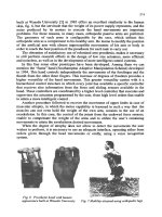
show the efficiency of the methods in grasping and regrasping [7]. As one
typical example we show here the rotation of a sphere by regrasping with
a four-fingered hand. A typical grasp pattern as developed in [7] is given
with Figure 6.10, which is self-explaining. The sequence of finger positions
in performing this task is illustrated by the pictures of Figure 6.11. We
see that the above discussed optimizations generate meaningful sequences
of finger operations.
The theories for grasping and for the hand, the finger design and the
hand-hardware are verified by experiments, rotation of an ellipsoid, re-
grasping of a cuboid and manipulation of a raw egg. The last mentioned
experiment also has been presented at the Hannover Industrial Fair 1994.
We show here only the regrasping experiment for a cuboid which is held
against gravity. Its weight amounts to 195 g, its size is 15 × 25 × 40 mm.
6.4. Examples
173
i
VME bus
11-=111
i "-
oomputer
computer SUN
486 CPU
workstation
finger electronics
(filter, power supply)
o
o
E
pressure sensor 1( ~ potentiom?ter I i ="-
I~__ drive unit
Figure 6.9: Hardware scheme of the TUM-hydraulic hand.
hand
finger 1
finger 2
finger 3
finger 4
0 time [s]
positioning and odentation of the hand
closing the finger ~ opening the finger
[~] vertical dosing ~ vertical opening
manipulation ~JJ hold
Figure 6,10: Grasping pattern [7].
15.44
174
Chapter 6. Grasping optimization and control
Figure 6.11: Rotating a sphere by a four-fingered hand [7].


![Adamsen, Paul B. - Frameworks for Complex System Development [CRC Press 2000] Episode 1 Part 4 ppsx](https://media.store123doc.com/images/document/2014_08/07/medium_svr1407381622.jpg)