Control of Redundant Robot Manipulators - R.V. Patel and F. Shadpey Part 3 pot
Bạn đang xem bản rút gọn của tài liệu. Xem và tải ngay bản đầy đủ của tài liệu tại đây (194.26 KB, 15 trang )
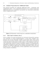
2.4
Analytic Expre
ssion for Additional T
asks
The general strategies for defining additional tasks inequality and
optimization tasks were explained in Section 2.3.1.4. In this section, the
additional tasks most commonly encountered are formulated analytically
under configuration control.
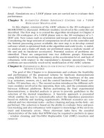
Figure 2.3 Kinematic control loop for a redundant manipulator
2.4.1Joint Limit Avoidance (JLA)
Joint variables of actual mechanisms are obviously limited by mechan-
ical constraints. In actual implementations, if some joint variables com-
puted by the inverse kinematic module exceed their limits, these joints
would be fixed at their extreme values which would restrict movement in
certain directions in task space. In this section, we first introduce some rele-
vant terminology, based on which a feasibility analysis of using kinematic
redundancy resolution for joint limit avoidance will be presented. Then, we
shall use two different approaches for defining algorithms which solve the
problem of JLA. The performance of these algorithms will be analyzed by
using computer simulations.
q
q
·
Redundancy
Resolu
tion
+
+
+
-
Forward Kinematics
+
-
q
··
+
-
X
d
X
··
d
X
·
d
X
X
·
K
P
K
V
J
·
e
J
e
J
e
q
·
q
·
P
20 2 Redundant Manipulators: Kinematic Analysis and Redundancy Resolution
2.4 Analytic Expression for Additional Tasks21
2.4.1.1 Definition of Terms and Feasibility Analysis
The reachable workspace of a robot manipulator is defined by the geo-
metrical locus of the position and orientation (pose) of the end-effector,
, when the joint variables,, range between two
extreme values.
(2.4.1)
The volume of the reachable workspace is finite, connected and, therefore,
is entirely defined by its boundary surface. Obviously on this boundary,
some loss of mobility occurs. Therefore the Jacobian matrix becomes rank
deficient. The boundary of the reachable workspace can be found numeri-
cally by constrained optimization routines, or by applying an inverse kine-
matics algorithm [62]. As an example, in Figure 2.4, we show the reachable
workspace of a two-link manipulator (using an optimization based
approach).
In [8] the term “aspects” is used to denote the subspaces of the accessible
volume in joint space in which the solution of the inverse kinematic func-
tion of equation (2.2.1) is unique if n=m, or if n-m variables are fixed when
n>m . The boundaries of the aspects are defined by the singularities of the
Jacobian matrix J
e
. Therefore, the interior of each aspect is free from singu-
larities. Each aspect in joint space corresponds to a convex subspace of the
reachable workspace. In Figure 2.4.a, we show the accessible volume in
joint space and its corresponding image in task space (Figure 2.4.b). From
these plots, it is obvious that if the desired task trajectory lies inside two dif-
ferent aspects, the inverse kinematics of the manipulator fails to provide a
continuous joint trajectory between the initial and the final points. There-
fore, this trajectory is not practically realizable without re-configuration of
the manipulator at or near the singular configuration. In particular, it is easy
to see that for the two-link planar manipulator, with joint limits indicated in
Figure 2.4.a and the reachable workspace shown in Figure 2.4.b, we may
encounter the following possibilities (Figure 2.5):
The path AB (the first letter indicates the initial point) is not realiz-
able.
The path CE via the intermediate point D is not realizable.
The same path CE via F is realizable.
y
m
q
n
nm
q
imin
q
i
q
imax
i=1,2, ,n
Figure 2.4 Reachable workspace of a 2-DOF manipulator in terms of
a) joint limits, b) reachable workspace
The path GH with initial joint position is not realizable.
The same path GH by the initial configuration is realizable
Note that by “unrealizable” we mean that there exists no continuous
joint trajectory (that can be provided by the inverse kinematics) which
starts from the initial configuration and satisfies the task trajectory without
violating the joint limits. Thus, for realizing a task comprising motion from
an initial pose to a final one, several problems may be considered, and the
solutions for some of them may not be achievable by the redundancy reso-
lution module. For instance, task AB is not realizable, but tasks CE and GH
can be realized by means of a joint limit avoidance algorithm.
Although the analyzed example is concerned with a non-redundant
manipulator, the main concepts are applicable to redundant manipulators
under configuration control with the only difference being that, in the
redundant case, the augmented task consists of the main and additional
tasks which are usually not defined in the same coordinates. Therefore, the
geometrical interpretation of the aspects and reachable workspace will, in
general, be different in the case of redundant manipulators.
(b)(a)
-50 0 50
-150
-100
-50
0
50
100
150
q
1
q2
Accesible volume in joint space
qmax(1)qmin(1)
qmin(2)
qmax(2)
( q2 > 0 )( q2 < 0 )
( q2 > 0 )
-2 0
2
-3
-2
-1
0
1
2
3
Reachable works
p
ace
2-axes manipulator
q
2
0
q
2
0
22 2 Redundant Manipulators: Kinematic Analysis and Redundancy Resolution
2.4 Analytic Expression for Additional Tasks23
2.4.1.2 Description of the Algorithms
Under the configuration control approach, the criterion of joint limit
avoidance should be formulated as a kinematic constraint function. In the
following, we present two different approaches for this formulation:
Using inequality constraints which become active only when one or
more of the limits are violated.
Defining the secondary task as minimization of a desired cost func-
tion.
Figure 2.5 Feasibility of different trajectories for a 2-DOF manipulator
2.4.1.3 Approach I: Using Inequality Constraints
In this approach, the basic equations for the JLA algorithm are as fol-
lows. The joint limits are presented as a set of inequality constraints. If all
the computed values of the joint variables satisfy the inequalities, the
redundancy can be used for other tasks. However if one or more of these
inequalities are violated, the JLA secondary task should be activated. This
task is defined as follows:
-
2
-
1.5
-
1
-
0.5 0 0.5 1 1.5 2
-2
-
1.5
-1
-
0.5
0
0.5
1
1.5
2
gp
pp
____ positive aspect q2 > 0
negative aspect q2 < 0
A
E
H
G
C
F
D
B
(2.4.2)
where q
m
replaces either the maximum or the minimum values of the joints
for i =1,2, ,n, and the corresponding constraint Jacobian J
c
is defined by
the equation:
(2.4.3)
where e
i
ist
he
ith column
of
the identity matr
ix.
For smooth incorporation
of the inequalit
y constraint into the
inverse kinematics, it is desirable to
define a “buffer” region where the relative importance of the JLA task pro-
gressively incr
ea
ses. To
define this
buf
fer
, the following scheme is used
[64]. When the inequality constraint is inactive, the corresponding weight
is zero, and on entering the “buffer” region increases gradually to its
maximum value. Mathematically, we can formulate this weight selection
procedure (i.e. ) as follows:
(2.4.4)
where W
0
and are user-defined constants representing the coefficient for
the weight and width of the buffer region respectively.
2.4.1.4 Approach II: Optimization Constraint
The basic idea in the second approach is to define a kinematic objective
function which is to be minimized. For joint limit avoidance, the following
function has been suggested:
Z
i
g
i
q q
i
==
Z
d
i
q
m
i
=
J
c
i
q
Z
i
e
i
T
==
W
c
i
q
i
q
imax
W
c
i
0=
W
c
i
W
0
4
-
1
q
imax
q
i
–
cos+=
W
c
i
W
0
2
=
q
i
q
imax
–
q
imax
– q
i
q
imax
q
i
q
imax
if
if
if
24 2 Redundant Manipulators: Kinematic Analysis and Redundancy Resolution
2.4
Analytic Expre
ssion for Ad
ditional
Ta
sk
s2
5
(2.4.5)
where q
c
is the center position around which we wish to minimize the
movement and is the difference between the maximum and the mini-
mum values of the joints. Then, the redundancy resolution problem is to
define a joint trajectory which optimizes equation (2.4.5) subject to the end-
effector position.
In Klein [38], it is mentioned that although the quadratic form of equa-
tion (2.4.5) is the most used function for this purpose, a better function
which reflects the objective of joint limit avoidance has the form:
(2.4.6)
However, since the infinity norm is not a differentiable function, he pro-
posed to use some finite order p-norm (p > 2):
(2.4.7)
For most practical problems, p=6 gives good results. Note that in equation
(2.4.7), the different joints have the same importance in the objective func-
tion. As an alternative to this formulation, we can introduce a diagonal
weighting matrix. The new objective function has the following form:
(2.4.8)
where K is an diagonal matrix. The Jacobian and the desired values
for this additional task are calculated as mentioned in and (2.3.28).
2.4.1.5Performance Evaluation and Comparison
Based on these approaches, two algorithms were implemented. The
simulations were carried out on a three-link planar manipulator with link
lengths (0.75m, 0.75m, 0.5m), qmin= [-90 -60 -75] degrees and qmax= [45
75 45]. The reachable workspace and the desired trajectory are shown in
Figure 2.6.
q
q
i
q
c
i
–
q
i
-
2
i 1=
n
=
q
max
q
i
q
c
i
–
q
i
c
–
q
==
c
–
q
p
=
K
c
–
q
p
=
nn
Figure 2.6 Reachable workspace and desired trajectory for a 3-DOF
planar arm
1- Inequality constraint approach: Figure 2.7a shows the joint variables
when the JLA provision was not activated. In this case, the third joint vio-
lates its minimum limit. In the second simulation, the JLA provision based
on the first approach has been used with the nominal selected values
W
0
=100, W
v
=5, W
e
=10 , and the buffer region = 5 (degrees). Figure 2.7b
shows that in this case, the third joint variable does not violate its limit.
Note that by adjusting W
0
, the discontinuity of the joint motion resulting
from the nature of the inequality constrained formulation, can be con-
trolled.
2- Optimization approach: The following simulation used the optimi-
zation based JLA ( p=2 ). Figure 2.8(a) shows that the third joint variable
enters the buffer region. Figure 2.8(b) shows the results for p=4 . As we can
see, in this case all joints stay far from their limits. Figure 2.9 shows the
third joint variable for different approaches. As we can see, for this special
case, both methods are successful in following the desired trajectory while
avoiding the joint limits. Obviously, the optimization method ( p =4) has the
best performance, since, the joint values are kept from approaching the lim-
its. This is in contrast to the inequality approach in which the joints move
freely until coming close to the limits where the JLA becomes active and
-
1.5
-
1
-
0.5 0 0.5 1 1.5 2 2.5
-
1.5
-1
-
0.5
0
0.5
1
1.5
26 2 Redundant Manipulators: Kinematic Analysis and Redundancy Resolution
2.4
Analytic Expre
ssion for Ad
ditional
Ta
sk
s2
7
prevents the manipulator from exceeding the joint limits. However, the
optimization approach is computationally expensive (especially when the
number of joints increases) compared to the simple formulation of the ine-
quality constrained approach. Therefore, the inequality constrained
approach is preferable for real-time implementations.
Figure 2.7 Simulation results for JLA using the inequality constraint
approach
0 0.2 0.4 0.6 0.8 1 1.2 1.4 1.6 1.8
-80
-60
-40
-20
0
20
40
Time
(
s
)
Joint variables ( free motion )
q3
q1
q2
qmin(3
)
deg
0 0.2 0.4 0.6 0.8 1 1.2 1.4 1.6 1.8
-80
-60
-40
-20
0
20
40
Time
(
s
)
Joint variables (Inequality constraint)
q1
q3
qmin(3
)
q2
Adjustable slope
deg
a) JLA inactive
b) JLA active
2.4.2 Static and Moving Obstacle Collision Avoidance
In this section, an outline of an algorithm for the 2-D workspace of a
planar arm is given. The extension of the algorithm to a 3-D workspace and
simulation results are given in Chapter 3.
2.4.2.1 Algorithm Description
As in the JLA case, Static (and Moving) Obstacle Collision Avoidance
is achieved using an inequality constraint. The following steps are followed
[14]:
Distance calculation
Decision making (if there is a risk of collision for a link)
Calculation of critical distance - the closest point on the link to the
object.
Utilizing redundancy to inhibit the motion of the critical point
towards the object.
For the 2-D workspace, links are modeled by straight lines and the
objects are assumed to be circles. Each object is enclosed in a fictitious pro-
tection shield (represented by a circle) called the Surface of Influence
(SOI). The first step involves distance calculation to find the location of the
point X
c
(called the critical point) on each link that is nearest to the obstacle
by the procedure indicated in Figure 2.10. This algorithm is executed for
each link and each obstacle. Then, if any of the critical distances is less
than the SOI, this constraint becomes active. In this case, we define the fol-
lowing kinematic function as the additional task:
(2.4.9)
The derivative of the additional task is given below.
(2.4.10)
where
is
the time
deri
vative of the ob
ject
’s
pose and is related to the
object’s
Cartesian velocity through a linear
mapping [5]. The
desired values
for the active constraints are:
d
c
i
Z
i
g
i
qt r
O
d
c
i
–==
Z
·
i
q
g
i
q
·
t
g
i
+ u
i
T
q
X
c
i
q
·
X
·
o
–
–==
X
·
o
28 2 Redundant Manipulators: Kinematic Analysis and Redundancy Resolution
2.4 Analytic Expression for Additional Tasks29
Fi
gur
e 2.8 Si
mulation results for
JLA
using the optimization approach
0 0.2 0.4 0.6 0.8 1 1.2 1.4 1.6 1.
8
-80
-60
-40
-20
0
20
40
Time
(
s
)
Joint variables (Optimization Constraint P=2)
q3
q2
q1
(a) p=2
qmin(3)
deg
(b) p=4
0 0.2 0.4 0.6 0.8 1 1.2 1.4 1.6 1.8
-80
-60
-40
-20
0
20
40
Time
(
s
)
Joint variables (Optimization Constraint P=4)
q1
q2
q3
qmin(3
)
deg
Fi
gure
2.9 Co
mparison between diff
erent
JLA approaches
Figure 2.10 Critical distance calculation
0 0.2 0.4 0.6 0.8 1 1.2 1.4 1.6 1.8
-80
-75
-70
-65
-60
-55
-50
-45
-40
Time
(
s
)
Joint variable q3
Optimization method P=4
Opt. P=2
free motioninequality constraint
qmin(3
)
deg
SO
I
u
i
X
c
i
X
o
–
d
c
i
=
d
c
i
X
c
i
X
o
–=
X
c
i
X
i
i
e
i
+=
i
e
i
T
X
o
X
i
–=
e
i
X
i 1+
X
i
–l
i
=
X
O
d
c
i
R
o
X
c
i
X
i 1+
L
i
X
i
Link i
30 2 Redundant Manipulators: Kinematic Analysis and Redundancy Resolution
2.4
Analytic Expre
ssion for Ad
ditional
Ta
sk
s3
1
(2.4.11)
Note that we still need to calculate the Jacobian of the active constraints
and its derivative. First, an intermediate term is defined as the Jacobian of
the critical point, i.e.,
(2.4.12)
Then the Jacobian and its derivative are calculated as:
(2.4.13)
(2.4.14)
2.4.3 Posture Optimization (Task Compatibility)
Compliant motion control and force control are mainly needed for tasks
involving heavy interaction with the environment. For this reason, an
appealing additional task is to position the arm in a posture which requires
minimum torque for a desired force in a certain direction. In this section, a
kinematic index for measuring task compatibility is introduced. In section
4.3.2, it is incorporated as an additional task in the Augmented Hybrid
Impedance Control (AHIC) scheme.
Similar to the manipulability ellipsoid introduced by Yoshikawa [97], a
force ellipsoid can be defined by: , where F
e
is the environ-
ment reaction force. The optimal direction for exerting the force is along
the major axis of the force ellipsoid which coincides with the eigenvector of
the matrix corresponding to its largest eigenvalue (Figure 2.11.a).
The force transfer ratio along a certain direction is equal to the distance
from the center to the surface of the force ellipsoid along this vector - see
Figure 2.11.b where u is the unit vector along the desired direction and is
the force transmission ratio along u . Since u is a point on the surface of
the ellipsoid, it should satisfy the following equation:
(2.4.15)
which gives . Hence, Chiu [13] proposed to maxi-
Z
i
d
Z
·
i
d
Z
··
i
d
0
===
J
X
c
i
q
X
c
i
=
J
c
i
u
i
T
– J
X
ci
=
J
·
c
i
z
·
i
d
c
i
u
i
T
J
X
ci
1
d
c
i
X
·
c
i
X
·
o
–J
X
ci
u
i
T
J
·
X
ci
++=
F
e
T
J
e
J
e
T
F
e
J
e
J
e
T
u
T
J
e
J
e
T
u 1=
u
T
J
e
J
e
T
u
12–
=
mize the following kinematic function (task compatibility index)
(2.4.16)
The desired value and the Jacobian for this additional task can be defined
according to the procedure in Section 2.3.1.4 in this chapter. Simulation
results are given in Section 4.3.2 .
Figure 2.11 a) Force ellipsoid, b) Force transfer ratio in direction u
2.5
Conclusions
In this chapter, the basic issues needed for the analysis of kinematically
redundant manipulators were presented. Dif
ferent redundancy resolution
schemes were reviewed. Based on
this review
,
configuration cont
ro
l
at
the
acceleration level was found to be the most suitable approach to be used in
a
force and compliant motion control
scheme for redundant manipulators.
However, most of the redundancy resolution schemes at the acceleration
level suffer from uncontrolled self-motion. In this section, the sources of
this problem were
presented. Their solutions
wil
l be presented
in Chapters
4 and 5. The formulation of the additional tasks to be used by the redun-
dancy resolution module were presented in this chapter. Joint limit avoid-
ance which is one of the most useful additional tasks was studied in detail.
q
2
=
1
max
1
mi
n
-
major axis
mi
nor
axis
u
(a)
(b)
32 2 Redundant Manipulators: Kinematic Analysis and Redundancy Resolution
2.5
Conclusio
ns
33
The basic formulation of static and moving obstacle collision avoidance
task in 2D workspace was presented. We are now in a position to extend the
proposed redundancy resolution scheme to the 3D workspace of REDI-
ESTRO and evaluate the results by simulation and experiments.
CHAPTER 3 COLLISION AVOIDANCE FOR A 7-DOF REDUNDANT MANIPULATOR
3.1 Introduction
Collision detection and obstacle avoidance are two features that play an
important role in fully or partly autonomous operations of robotic manipu-
lators in cluttered environments. A compact and fast collision-avoidance
scheme would be particularly useful for robotic applications in space,
underwater, and hazardous environments. Collision avoidance for robot
manipulators can be divided into two categories: end-effector level and link
level. Much of the work reported to date has dealt with obstacle avoidance
as an off-line path planning problem, i.e., find a collision-free path for the
end-effector [7], [28], or by mapping the obstacle into joint space, find a
collision-free path in joint space [36], [11]. These methods are not applica-
ble to environments with moving objects. Moreover, for non-redundant
manipulators, tracking an end-effector trajectory while avoiding collisions
with obstacles at the link level, or self-collision avoidance, is often not
achievable. Kinematic redundancy has been recognized as a major charac-
teristic for operation of a robot in a cluttered environment [33]. For redun-
dant manipulators, a real-time collision avoidance approach has been
developed recently by Seraji and Bon [70] that formulates the problem as a
force-control problem so that the task of collision avoidance is solved pri-
marily by augmenting the manipulator control strategy.
To implement a real-time collision-avoidance scheme, three major
areas: redundancy resolution, robot and environment modeling, and dis-
tance calculation need to be investigated. Obviously, the accuracy with
which a robot arm and its environment are modeled is directly related to the
real-time control requirements. Greater detail in modeling results in higher
complexity when computing the critical distances between an obstacle and
the manipulator. Much of this computation can be avoided if the distance
measurements are obtained by a proximity sensing system such as the
“Sensor Skin” described in [68]. For situations where proximity sensors are
not available, a possible solution is to use simple geometric primitives to
3Collision Avoidance for a 7-DOF Redundant
Manipulator
R.V. Patel and F. Shadpey: Contr. of Redundant Robot Manipulators, LNCIS 316, pp. 35–78, 2005.
© Springer-Verlag Berlin Heidelberg 2005