Electroactive Polymers for Robotic Applications - Kim & Tadokoro (Eds.) Part 12 pps
Bạn đang xem bản rút gọn của tài liệu. Xem và tải ngay bản đầy đủ của tài liệu tại đây (544.34 KB, 20 trang )
Robotic Application of IPMC Actuators with Redoping Capability 213
Figure 8.15. Poincaré map
Because
*
),
can not be obtained analytically, we computed them numerically by
computer simulation as
»
»
»
¼
º
«
«
«
¬
ª
uuu
uuu
uuu
)
210
101
210
1029.21010.71044.1
1055.11059.11030.1
1073.31094.31082.2
(8.5)
»
»
»
¼
º
«
«
«
¬
ª
u
u
u
*
2
2
3
1026.4
1042.5
1025.9
(8.6)
The weighting matrices Q, r are determined as follows:
1. Check the limit of stability; let q
1f
, q
2f
, q
3f
be the quantity of state in the
stability limit, respectively, and check them by numerical simulation, that
is, we search the maximum perturbation that the robot does not even fall
down.
2. Determine Q; Q is set as
)./1 ,/1 ,/1(diag
2
3
2
2
2
1 fff
qqqQ
3. Determine r; r is adjusted manually to obtain a suitable input.
Figure 8.16 shows the simulation results of feedback control; deviations are
included in initial conditions. Q, r, and feedback vector F are
)108.73 ,109.61 ,1042.3(diag
135
uuu Q
0.1 r
]1080.9 ,1002.1 ,1076.7[
121
uuu F
J
¦
)(qP
q
0
q
214 M. Yamakitaet al.
(a)
(b)
(c)
Figure 8.16. Simulation results of feedback control (a) angular positions (b) transition of
1
q
G
(c) input voltage
Figure 8.16(a) shows angular positions, figure (b) shows the transition of
1
q
G
on
Poincaré section
6
, and figure (c) shows the input voltage to the actuator, the total
of the open-loop signal and feedback signal. From the results, it is observed that
the convergence to steady state becomes fast in comparison to open-loop control.
The validity of this feedback control was investigated, but more detailed analysis
of the basin of attraction and the robustness of the control is left for future work.
Robotic Application of IPMC Actuators with Redoping Capability 215
8.4.3 Doping Effect on Walking
As shown in the previous section, the bending characteristics of IPMC film are
highly affected by the doped counterion. There exist possibilities to change the
properties of the actuator according to the environment or purpose. If we consider
walking application, we can change the property so that the actuator is suitable for
slow walking with low energy consumption or fast walking with high energy
consumption, or possibly running. We investigate the possibility of adaptation with
doping of the actuator for walking control by numerical simulations 0. Recall that
the doped ion can be exchanged as many times as required.
We compare walking speeds and walking efficiencies with actuators composed
of IPMC films doped with Na
+
and Cs
+
for the same input voltage. The input
voltage is rectangular, its amplitude is 2.5 V, and it is applied to the system in an
open-loop fashion. The parameters of the robot are set as m
l
=5.0 g, m
h
=10.0 g,
a=50.0 mm, b=50.0 mm, l=100.0 mm, r
h
=4.0 mm, r
f
= 0.0 mm, and g=9.81 m/s
2
.
We assume also that in the simulation the number of units connected in parallel
and series is set as 4 and 3, respectively.
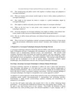
Figure 8.17(a) shows a plot of average walking speed vs. the applied frequency
of the input where the solid line shows the plot for the actuator with Na
+
and dotted
line for that with Cs
+
. From the figure, it can be seen that if the same control
frequency input is applied to the robot, faster walking is realized by the actuator
doped with Na
+
rather than by that with Cs
+
. The maximum speed of the robot
doped with Na
+
is higher than that with Cs
+
. Note here that this kind of property
may not exist if the parameters of the robot are not designed properly. So the
design of the robot is important for the doping to be effective for walking. Figure
8.17(b) shows a plot of walking speed vs. the average consumed power. Because
the input current for the actuator is almost irrelevant to the walking pattern, the
peak value of the injected current of the actuator doped with Na
+
is large, and the
corresponding consumed power is large.
From the observation, it can be suggested that if the input voltage is the same,
the actuator doped with Na
+
realizes high-speed walking with high energy
consumption, and the one doped with Cs
+
can generate a slow walking pattern with
low energy consumption when the mass is rather heavy, i.e., m=5 g. On the other
hand, when m=1 g, the actuator with Cs
+
can realize a wide range of walking
speeds with low energy consumption. Note here that even if the average input
power is increased in the case of Cs
+
, the walking speed is not increased because
the walking pattern is not proper and the energy dissipated in a collision is
increased.
216 M. Yamakitaet al.
(a)
(b)
Figure 8.17. Simulation results of the doping effect on bipedal walking (a) average speed
vs. walking cycle (b) average speed vs. average input power
8.5 Application to Snakelike Robot
In the last section, it was shown that the efficiency of walking with different
walking speeds was confirmed by numerical simulation. In this section, the effect
is checked by a snakelike robot swimming in water experimentally.
Robotic Application of IPMC Actuators with Redoping Capability 217
8.5.1 Snakelike Robot
Figure 8.18 shows an experimental machine, a three-link snakelike swimming
robot with IPMC actuators. The frame of the robot is made of styrene foam. Thin
fins are attached to the bottom of the body frame, and each frame is connected by
an IPMC film. The total mass of the robot is 0.6 g and its total length is 120 mm.
The IPMC film which we used in this experiment is Nafion
®
117 (by DuPont)
plated with gold; the thickness of this film is about 200 ȝm in a wet condition, and
it was cut into a ribbon with a width of 2 mm and length of 20 mm.
To check the performance of the robot, we also performed experiments using
the snakelike robot as shown in Figure 8.18.
Figure 8.19 shows the experimental results with input signals whose cycle is 2
s, amplitude is 2.5 V, phase shift is 90
,q
and the kind of counterion is sodium
(Na
+
). From figures (a) and (b), it can be confirmed that the robot performs an
undulating motion and moves forward. Figure 8.20 shows sequential photographs
of the experiment. For more details of the experimental setup and the properties of
the motions, refer to 0.
Figure 8.18. Snakelike robot using IPMC
218 M. Yamakitaet al.
(a)
(b)
(c)
Figure 8.19. Experimental results (a) trajectory of head position (b) angular positions (c)
input voltages
Robotic Application of IPMC Actuators with Redoping Capability 219
Figure 8.20. Sequencial photographs of the experiment
8.5.2 Doping Effect
To verify the doping effect, we performed experiments on IPMC actuators which
were doped with Na
+
, Cs
+
and TEA
+
as counterions. We compare propulsive speed
and efficiencies of the actuators doped with each ion for the same input voltage.
The inputs voltages were square pulses whose amplitude was 2.5 V and phase shift
was 90
,q
and we repeated measurements at various input frequencies.
In Figure 8.21 (a), the average propulsive speed vs. consumed power is plotted.
The snakelike robot doped with Na
+
can move faster; however, consumed power is
large. If it need not move at high speed, we should use the actuators doped with
other counterions that can be driven by low power. Figure 8.21(b) shows the
average propulsion speed vs. power consumed per distance. If there is no limit to
the capacity of a power source, it can be considered that the actuators doped with
Na
+
are effective because the robot can move for a short time; however, there is a
region of low consumed power achieved only by the robot doped with TEA
+
.
From the observation, it can be summarized that if the input voltage is the
same, the actuator doped with Na
+
realizes a high-speed swimming motion with
high energy consumption, the one doped with TEA
+
can generate slow swimming
speed with low energy consumption, and the one doped with Cs
+
has
characteristics between those of Na
+
and TEA
+
. Note that the actuators can be
220 M. Yamakitaet al.
adjusted to various characteristics by selecting an appropriate counterion or by
mixing several ions in appropriate proportions.
(a)
(b)
Figure 8.21. Experimental results of doping effect (a) consumed power vs. average speed
(b) consumed energy per distance vs. average speed
8.6 Control of Partial Doping Effect by Exercise
The doping effect is caused by exchanging counterions and a higher condensed
counterion is doped into IPMC films. The doping of the counterions is easily done
just putting the actuators in a solution containing the target counterion just as the
robots take a bath containing a nutritional supplement. When the robots cannot
Robotic Application of IPMC Actuators with Redoping Capability 221
take a bath, liquid containing the counterion can be delivered to the actuators
through tubes like blood vessels. Figure 8.22(a) illustrates these doping processes.
If the speed of changing the ion can be controlled by exercises, i.e., bending IPMC
films, the property of particular actuators can be changed by such motions. This
phenomenon can be considered similar to muscles in a human body that can be
trained by exercise for a particular purpose, as in Figure 8.22 (b).
(a)
(b)
Figure 8.22. Image of adaptation by doping (a) Process of ion-exchange (b) Adaptation of
partial elements by doping
8.6.1 Experiment
To investigate the possibility of the effect in IPMC actuators, we conducted an
experiment as follows. Two linear actuators doped with TEA
+
were prepared, and
one of the actuators was just immersed in the Na
2
SO
4
solution with Na
+
. On the
other hand, another actuator was actuated in the same solution so that the bending
motion was caused frequently.
At every interval, the characteristics of the two actuators were measured. In our
experiment, step responses for a constant voltage input are stored.
The length, width, and thickness of the films were 25 mm, 2 mm, and 200 ȝm,
respectively, and they were immersed in the liquid by 15 mm. For the activated
film, a rectangular input whose levels were
11l
V and whose frequency was
0.5 s was injected. The step responses of the films were measured at 0, 10, 30, 60,
120, and 180 minutes where the input voltage was 2.0 V.
222 M. Yamakitaet al.
Case A Case B
(a)
(b)
Figure 8.23. Experimental result of doping progress (a) current (b) peak value of
current
Robotic Application of IPMC Actuators with Redoping Capability 223
When the step response was measured, the actuators were immersed in pure water
for 10 minutes to avoid changes due to the mechanical effects of motion.
Figure 8.23 shows the experimental results. In the figure, (a) shows the changes
in the current profile for each step input, and (b) shows peak values of the current,
with respect to the intervals. From the figure, it can be seen that the peak values of
the current increased according to the increase of the interval, and the property was
changed from the property of TEA
+
to that of Na
+
. Note that the property of the
actuator immersed with motion changed more quickly than that without motion.
Actually, the property of the film without motion at 180 minutes was achieved by
the film with motion at 30 minutes.
8.7 Conclusions
We have discussed the development of a linear actuator using IPMC materials and
its applications to a walking robot and a snakelike robot. In this monograph, the
doping effects on motion were focused on especially, and it was shown by
numerical simulations of walking control and by an experiment of a swimming
control of the snakelike robot that the properties of the actuator can be adjusted
according to particular motions, i.e., slow speed motion with low energy
consumption or high speed motion with high energy consumption. Also, a
possibility that some actuators distributed in a system can be partially doped with a
desired ion by moving the actuators mechanically was shown by a preliminary
experiment. The authors consider that the developed IPMC linear actuator can be
used for biomimetic control systems where the properties of the system can be
adapted to an environment using doping effects.
To apply the artificial muscle actuator to a general robotic system, there exist a
lot of problems such as limitation of output force; however, we think the mutual
evolution of improvement of actuator technology and design of control system is
important for further applications.
8.8 Acknowledgments
The contents of the paper are collections of works in the last few years by co-
workers in the development of the IPMC linear actuator. The authors give their
special thanks to Mr. Kaneda, Mr. Kozuki, and Mr. Sera at Tokyo Tech.
8.9 References
Y. Bar-Cohen, Electroactive Polymer (EAP) Actuators as Artificial Muscles: Reality,
Potential, and Challenges, SPIE Press, 2001.
K. Oguro, Y. Kawami and H. Takenaka, ``Bending of an ion-conducting polymer film-
electrode composite by an electric stimulus at low voltage,'' Journal of Micromachine
Society, 5, 27-30, 1992. (in Japanese)
224 M. Yamakitaet al.
S. Guo, T. Fukuda, K. Kosuge, F. Arai, K. Oguro and M. Negoro, ``Micro catheter system
with active guide wire,'' Proc. of IEEE Int. Conf. on Robotics and Automation, pp.79-
84, 1995.
EAMEX Corporation,
M. Mojarrad and M. Shahinpoor, ``Biomimetic robotic propulsion using polymeric artificial
muscles,'' Proc. of IEEE Int. Conf. on Robotics and Automation, pp.2152-2157, 1997.
S. Guo, T. Fukuda and K. Asaka, ``A new type of fish-like underwater microrobot,''
IEEE/ASME Trans. on Mechatronics, Vol. 8, No. 1, pp.136-141, 2003.
J. Jung, B. Kim, Y. Tak and J. O. Park, ``Undulatory tadpole robot (TadRob) using ionic
polymer metal composite (IPMC) actuator,'' Proc. of IEEE/RSJ Int. Conf. on
Intelligent Robots and Systems, pp.2133-2138, 2003.
J. W. Paquette, K. J. Kim and W. Yim, ``Aquatic robotic propulsor using ionic polymer-
metal composite artificial muscle,'' Proc. of IEEE/RSJ Int. Conf. on Intelligent Robots
and Systems, pp.1269-1274, 2004.
A. Punning M. Anton, M. Kruusmaa and A. Aabloo, ``A biologically inspired ray-like
underwater robot with electroactive polymer pectoral fins,'' Proc. of IEEE/ Int. Conf.
on Mechatronics and Robotics, Vol. 2, pp.241-245, 2004.
Y. Nakabo, T. Mukai, K. Ogawa, N. Ohnishi and K. Asaka, ``Biomimetic soft robot using
artificial muscle,'' in tutorial ``Electro-Active Polymer for Use in Robotics'',
IEEE/RSJ Int. Conf. on Intelligent Robots and Systems, 2004.
Y. Bar-Cohen, S. Leary, A. Yavrouian, K. Oguro, S. Tadokoro, J. Harrison, J. Smith and J.
Su, ``Challenges to the application of IPMC as actuators of planetary mechanisms,''
Proc. of SPIE Int. Symp. on Smart Structures and Materials, EAPAD, Vol. 3987,
2000.
S. Guo, S. Hata, K. Sugumoto, T. Fukuda and K. Oguro, ``Development of a new type of
capsule micropump,'' Proc. of IEEE Int. Conf. on Robotics and Automation, pp.2171-
2176, 1999.
S. Tadokoro, S. Yamagami, M. Ozawa, T. Kimura and T. Takamori, ``Multi-DOF device for
soft micromanipulation consisting of soft gel actuator elements,'' Proc. of IEEE Int.
Conf. on Robotics and Automation, pp.2177-2182, 1999.
S. Tadokoro, S. Fuji, M. Fushimi, R. Kanno, T. Kimura and T. Takamori, ``Development of
a distributed actuation device consisting of soft gel actuator elements,'' Proc. of IEEE
Int. Conf. on Robotics and Automation, pp.2155-2160, 1998.
M. Yamakita, N. Kamamichi, Y. Kaneda, K. Asaka and Z. W. Luo, ``Development of an
artificial muscle linear actuator using ionic polymer-metal composites,'' Advanced
Robotics, Vol. 18, No. 4, pp.383-399, 2004.
K. Onishi, S. Sewa, K. Asaka, N. Fujiwara and K. Oguro, ``The effects of counter ions on
characterization and performance of a solid polymer electrolyte actuator,''
Electrochemica Acta, Vol. 46, No. 8, pp.1233-1241, 2001.
Y. Kaneda, N. Kamamichi, M. Yamakita, K. Asaka and Z. W. Luo, ``Development of linear
artificial muscle actuator using ionic polymer -introduce nonlinear characteristics to
attain a higher steady gain-,'' Proc. of the Annual Conf. of RSJ, 2003. (in Japanese)
S. Tadokoro and T. Takamori, ``Modeling IPMC for design of actuation mechanisms,''
Electroactive Polymer (EAP) Actuators as Artificial Muscles, Reality, Potential, and
Challenges, Ed. Y. Bar-Cohen, SPIE Press, pp.331-366, 2001.
K. Asaka and K. Oguro, ``Bending of polyelectrolyte membrane platinum composites by
electric stimuli Part II. Response kinetics,'' Journal of Electroanalytical Chemistry,
480, pp.186-198, 2000.
S. Tadokoro, S. Yamagami and T. Takamori, ``An actuator model of ICPF for robotic
applications on the basis of physicochemical hypotheses,'' Proc. of IEEE Int. Conf. on
Robotics and Automation (ICRA), pp. 1340-1346, 2000.
Robotic Application of IPMC Actuators with Redoping Capability 225
S. Tadokoro, M. Fukuhara, Y. Maeba, M. Konyo, T. Takamori and K. Oguro, ``A
dynamical model of ICPF actuator considering ion-induced lateral strain for
molluskan robotics,'' Proc. of IEEE Int. Conf. on Robotics and Automation, pp. 2010-
2017, 2002.
K. Mallavarapu, K. Newbury and D. J. Leo, ''Feedback control of the bending response of
ionic polymer-metal composite actuators,'' Proc. of SPIE Int. Symp. on Smart
Structures and Materials, EAPAD, Vol. 4329, pp.301-310, 2001.
T. McGeer, ``Passive dynamic walking,'' The Int. Journal of Robotics Research, Vol. 9, No.
2, pp.62-82, 1990.
M. Yamakita, N. Kamamichi, T. Kozuki, K. Asaka and Z. W. Luo, ``Control of biped
walking robot with IPMC linear actuator,'' Proc. of IEEE/ASME Int. Conf. on
Advanced Intelligent Mechatronics, 2005.
M. Yamakita, N. Kamamichi, Y. Kaneda, K. Asaka and Z. W. Luo, ``IPMC linear actuator
with re-doping capability and its application to biped walking robot,'' Proc. of 3rd
IFAC Symposium on Mechatronic Systems, pp.359-364, 2004.
M. Yamakita, N. Kamamichi, T. Kozuki, K. Asaka and Z. W. Luo, ``A snake-like
swimming robot using IPMC actuator and verification of doping effect,'' Proc. of
IEEE/RSJ Int. Conf. on Intelligent Robots and Systems, 2005.
9
Applications of Ionic Polymer-Metal Composites:
Multiple-DOF Devices Using Soft Actuators and
Sensors
M. Konyo
1
, S. Tadokoro
2
, K. Asaka
3
1
Graduate School of Information Science, Tohoku University,
6-6-01 Aramaki Aza Aoba, Aoba-ku, Sendai 980-8579, Japan
2
Graduate School of Information Science, Tohoku University
3
Research Institute for Cell Engineering, National Institute of AIST,
1-8-31 Midorigaoka, Ikeda, Osaka, 563-8577, Japan
9.1 Introduction
The ionic polymer-metal composite (IPMC, which is also known as ICPF
*
) [1, 2]
is one of the electroactive polymers that have shown potential for practical
applications. IPMC is an electroless plated electroactive polymer (EAP) material
that bends when subjected to a voltage across its thickness (see Figure 9.1). IPMC
has several attractive EAP characteristics that include:
(1) Low drive voltage is 1.0 – 5.0 V).
(2) Relatively high response (up to several tens of Hertz).
(3) Soft material (E = 2.2 × 10
8
Pa).
(4) Possible to miniaturize (< 1 mm).
(5) Durability to many bending cycles (> 1 ×10
6
bending cycles).
(6) Can be activated in water or in a wet condition.
(7) Exhibits distributed actuation allowing production of mechanisms with
multiple degrees of freedom.
The IPMC generates a relatively small force where a cantilever-shaped actuator
(2 × 10 × 0.18 mm) can generate about 0.6 mN, and therefore its applications need
to be scoped accordingly. Some of the applications that were investigated for
IPMC include an active catheter system [3, 4], a distributed actuation device [5–7],
*
Kanno and Tadokoro named the Nafion-Pt composite ICPF (Ionic Conducting Polymer gel Film) in
1992. In the field of robotics, most researchers use the name ICPF, and it is well recognized.
228 M. Konyo, S. Tadokoro, and K. Asaka
an underwater robot [8], micromanipulators [9, 10], a micropump [11], a face-type
actuator [7], a wiper of an asteroid rover [12, 13], and a tactile haptic display for
virtual reality [14–17]. The actual number of applications that were considered is
still small, but the list is expected to grow in the coming years with the emergence
of requirements that account for the limitations while taking advantage of the
unique capabilities.
Figure 9.1. Ionic polymer metal composite (IPMC) actuator shown for Pt/Nafion composite
EAP
Many investigators have studied models for IPMC, with the largest number
addressing Nafion-Pt composite EAP [18–27].
A soft sensing system is also important for advanced applications of IPMC
actuators, because conventional solid sensors may cancel the flexibility of an
IPMC. One possible sensor would be an IPMC itself. An IPMC can also be used as
a sensor, because an electric potential will be generated across the composite when
the strip is bent suddenly. The authors showed that the velocity of deformation of
an IPMC strip was in proportion to the sensor output voltage and two kinds of
velocity-sensing systems were proposed [28]. One is a 3-DOF tactile sensor that
has four IPMC sensor modules combined in a cross shape and can detect both the
velocity and the direction of the motion of the center tip. Another is a patterned
IPMC strip that has both actuator and sensor functions. This strip can sense the
velocity of bending motion made by the actuator part.
In this chapter, we describe several robotic applications developed using IPMC
materials, which the authors have developed as attractive soft actuators and sensors.
In Sections 9.2 to 9.4, several applications of IPMC actuators which have soft
actuation mechanisms are described. We introduce several unique applications as
follows:
(1) Haptic interface for a virtual tactile display
(2) Distributed actuation device
(3) Soft micromanipulation device with three degrees of freedom
In Section 9.5, we focus on aspects of the sensor function of IPMC materials. The
following applications are described:
(1) 3-DOF tactile sensor
(2) Patterned sensor on an IPMC film
Applications of Ionic Polymer-Metal Composites 229
9.2. Haptic Interface for Virtual Tactile Display
9.2.1 Background
A novel technology to display to humans more realistic tactile sensation including
qualitative information will realize advanced telecommunication directly
connected to human physical skills and human mental sensibilities. A cutaneous
display in addition to a force display helps human dexterous telemanipulation for
use in medicine, space, and other extreme environments. For virtual reality
applications, a tactile display is also effective to produce human emotional
responses such as a rich texture feel, comfort of touch, and high presence of virtual
objects.
A number of tactile displays have been proposed for evoking the cutaneous
sense accepted by subcutaneous receptors for rough or frictional feeling on the
surface of an object [29]. Conventional mechanical stimulation displays are
equipped with a dumbbell-shaped vibration pin, a linear motor, and a pneumatic
device. Consequently, it is difficult for the subject to perform contact motion freely
in a 3-d space with this type of display due to the weight and size of its actuator .
EAP materials have many attractive characteristics as a soft and light actuator
for such a stimulation device. The authors have developed a tactile display using
IPMC actuators [14–17]. In our research, the target of tactile information is quite
different from conventional ones. Our display can produce a delicate touch
including even qualitative information such as a haptic impression or material feel
when we stroke the surface of cloth.
The most characteristic feature of tactile sensation is a diversity of perceptual
content. This variety is reflected in physical factors of target materials such as
rigidity, elasticity, viscosity, friction, and surface shapes. It is interesting that
tactile receptors in human skin cannot sense the physical factors directly. They can
detect only the inner skin deformations caused by contacting to the objects. This
suggests that the reproduction of the same physical factors of materials is not
necessary for representing the virtual touch of materials. Virtual touch needs only
the reproduction of internal deformations in the skin. Furthermore, a tactile illusion
can even be provided by reproduction of nervous activities of tactile receptors,
regardless of the inner deformations.
Based on this standpoint, several researchers proposed tactile display methods
that make a selective stimulation on each tactile receptor using a magnetic
oscillator and air pressure [30] and electrocutaneous stimulation [31]. However,
selectivity of stimuli for all kinds of receptors was not enough to reproduce various
tactile sensations. By using IMPC actuators, the authors proposed a tactile
synthesis method that could control three physical characteristics, which are
roughness, softness, and friction, as tunable parameters of textures. This method
realizes selective stimulations on each kind of tactile receptors based on its
temporal response characteristics [14–17].
In addition, an active perceptual process based on contact motion is very
important for human tactile perception. To confirm the feel against hands (haptic
impression) people use hand movements consciously or actively to clarify the
properties of an object. Such an active touch in connection with contact motion
230 M. Konyo, S. Tadokoro, and K. Asaka
excels passive sensory perception qualitatively and quantitatively. We successfully
developed a wearable tactile display presenting mechanical stimuli on a finger in
response to hand movements by using a small interface [16]. Almost no studies had
realized a wearable tactile display that could make a multi degree-of-freedom
mechanical stimulation on the skin.
In this chapter, haptic interfaces using IPMC actuators are described. Our
display can realize a selective stimulation on human skin. We also describe a
tactile synthesis method that can control three physical characteristics, which
consists of roughness, softness, and friction, as tunable parameters of textures.
9.2.2 Wearable Tactile Display Using ICPF Actuators
Haptic interfaces for presenting human tactile feel were developed using IPMC
actuators [14–17]. To express delicate tactile feel including even qualitative
information such as tactile impression or material feel, we need to control the
sensory fusion of elementary sensations that are generated by different sensory
receptors.
Conventional tactile displays could hardly control such delicate sensation
because it was difficult to make fine distributed stimuli on a human skin under the
limitation of their actuators such as magnetic oscillators, piezoelectric actuators,
shapememory alloy actuators, pneumatic devices, and so on. EAP materials have
many attractive characteristics as a soft and light actuators for such a stimulation
device. IPMC is suitable for the following reasons:
(1) High spatial resolution: The required spatial resolution for stimulating
sensory receptors, especially Meissner’s corpuscle in the finger tip, is less
than 2 mm. IPMC films are easy to shape, and their simple operating
mechanism allows miniaturizing a stimulator to make a high-density
distributed structure. Conventional actuators can hardly control such minute
force because of their heavy identical mass and high mechanical impedance.
IPMC has enough softness that special control methods are not required to
use the passive material property.
(2) Wide frequency range: Tactile display can stimulate several tactile
receptors selectively by changing frequency ranges because each tactile
receptor has different time response characteristics for vibratory stimulation
[17]. The required frequency range is from 5 Hz to 200 Hz to stimulate all
kinds of tactile receptors. The response speed of IPMC is fast enough to
make a vibratory stimulation on a skin higher than 200 Hz. This means that
IPMC can stimulate all receptors selectively.
(3) Stimuli in multiple directions: Each of the tactile receptors has selectivity
for the direction of mechanical stimuli. Meissner’s corpuscle detects
especially the shearing stress toward the skin surface. Figure 9.2 shows that
bending motions of an IPMC, which contacts with a surface of skin in a
tilted position, make a stress in both the normal direction and shearing
direction.
(4) Wearability: In human tactual perception, an active perceptual process
based on hand contact motion is very important. To generate the virtual
reality of tactile feel, we should move our hand actively and freely, and
Applications of Ionic Polymer-Metal Composites 231
receive appropriate stimuli in response to the hand movements. For
conventional mechanical stimulation devices of tactile display, it is difficult
to attach the device to a finger, so that the subjects cannot perform contact
motion freely in a 3-D space. An IPMC based wearable display was
successfully developed, which was made so smaller in size and weight that
there was no interference with hand movements [16].
(5) Safety: The low driving voltage (less than 5 V) is safe enough to touch with
a human finger directly.
IPMC
actuator
Bending
motion
Shearing stress
Normal stress
Human
skin
Figure 9.2. Multidirectional stimulation of a human skin using an IPMC actuator
(a) Fixed-type device (b) Wearable device
Figure 9.3. Overview of tactile displays
Flexible wiring board
Silicone
IPMC
Actuator
4 mm
3 mm
1 mm 2 mm
Au-Nafion type
IPMC Actuator
25 mm
Figure 9.4. Structure of ciliary device using IPMC actuators
232 M. Konyo, S. Tadokoro, and K. Asaka
In an early prototype [14], tactile feel has been presented as shown in Figure 9.3a.
In that case, subjects obtained only passive tactual perception because they could
not perform contact motion. As shown in Figure 9.3b, the new wearable device
[16] can be attached to the tip of a finger.
The structure of the wearable stimulation device is shown in Figure 9.4. The
ciliary part is provided with Nafion-Au composite actuators, where each cilium is 3
mm long and 2 mm wide, in 12 rows leaving 1 mm gaps horizontally and 1.5 mm
gaps vertically. All cilia are tilted 45° to transmit mechanical stimuli both in the
normal and the tangential directions to the surface of the skin efficiently as shown
in Figure 9.2. The power supply line of the IPMC is provided with a flexible
wiring board in to minimize restrictions on the hand, so the fingertip can be bent
flexibly. The use of silicon rubber of 25 × 25 × 8 [mm] applied to the base of the
ciliary part has made it possible to lighten the device to approximately 8 g
including the flexible wiring board.
An IPMC needs to be kept moistened because its actuators are operated by ionic
migration. Even in a little wet condition in the air, however, the device can provide
stimuli sufficiently for several minutes.
Figure 9.5 shows the total display system. The stimulation device is attached to
the middle finger tip. The system is designed to read positional information of the
hand using Polhemus' FASTRAK, which can read information according to a
magnetic field.
Fastrak
transmitter
System
Electronics
Unit
PC
Water bath
Fastrak
receiver
Human hand
DA
converter
Amp. Switchboard
12
(moving in the air)
Figure 9.5. Wearable tactile display system in response to virtual contact motion
9.2.3. Concept of the Selective Stimulation Method
In human skin, tactile receptors generate elementary sensations such as touch,
pressure, vibratory sensation, pain, temperature sense, and so on. A Tactile
impression is an integrated sensation of these elementary sensations. To present
tactile feel arbitrarily, stimuli applied to these receptors should be controlled
selectively and quantitatively. As mentioned previously, tactile receptors cannot
sense the physical factors of environments directly. They detect only the skin
deformation caused by contacting objects. A tactile illusion can be provided by
reproduction of activities of tactile receptors, regardless of the inner deformations.
Applications of Ionic Polymer-Metal Composites 233
Skin structures
Transmission of filtered information
Velocity sensor
FA I
Acceleration
sensor
FA II
Pressure sensor
SA I
Unspecified
SA II
Central nerve system
Original tactile infomation
Tactile perception
(Spatial-temporal information)
=
Relationship of information from several kinds of receptors
Decoding and combining of original spatial-temporal information
=
Alternative
Stimuli
Selective
stimulation
method
Nerve impulses
Mechano-
receptors
Figure 9.6. Concept of selective stimulation method
Figure 9.6 illustrates the concepts of the selective stimulation method. There are
four types of mechanoreceptors embedded in human fingers, FA I type (Meissner's
corpuscle), SA I type (Merkel corpuscle), FA II type (Pacinian corpuscle), and SA
II type (Ruffini endings) [32]. It is known that each receptor has temporal response
characteristics for mechanical stimulation and causes subjective sensation
corresponding to its responsive deformation. For example, SA I detects static
deformations of skin and produces static pressure sensation, and FA I detects the
velocity of the deformation and produces the sense of fluttering vibration. Tactile
impression is an integrated sensation of these elementary sensations. To present
tactile feel arbitrarily, stimuli applied to these receptors should be controlled
selectively.
The first problem is how to stimulate each receptor selectively. We have focused
on the frequency response characteristics of tactile receptors. Figure 9.7 [33]
illustrates the human detection threshold against vibratory stimuli, which
represents the sensibility of each receptor to frequency variation. A smaller
amplitude threshold means higher sensibility. This figure shows that there are three
frequency ranges in which the most sensitive receptor changes. In the lowest
frequency range, SA I is most sensitive relatively. The best becomes FA I in the
middle range and FA II in the highest range, respectively. This suggests that the
selective stimulation can be realized using these frequency characteristics, and
arbitral tactile feels can be produced by synthesizing several frequency components.