Dynamic Vision for Perception and Control of Motion - Ernst D. Dickmanns Part 5 potx
Bạn đang xem bản rút gọn của tài liệu. Xem và tải ngay bản đầy đủ của tài liệu tại đây (480.9 KB, 30 trang )
3.4 Behavioral Capabilities for Locomotion 105
control in an active vision system. By extending these types of explicit representa-
tions to all processes for perception, decision-making, and mission planning as
well as mission performance and monitoring, a very flexible overall system will re-
sult. These aspects have been discussed here to motivate the need for both smooth
parts of mission performance with nice continuity conditions alleviating percep-
tion, and sudden changes in behavior where sticking to the previous mode would
lead to failure (or probably disaster).
Efficient dynamic vision systems have to take advantage of continuity condi-
tions as long as they prevail; however, they always have to watch out for disconti-
nuities in motion, both of the subject’s body and of other object observed, to be
able to adjust readily. For example, a vehicle following the rightmost lane on a
road can be tracked efficiently using a simple motion model. However, when an
obstacle occurs suddenly in this lane, for example, a ball or an animal running onto
the road, there may be a harsh reaction to one side. At this moment, a new motion
phase begins, and it cannot be expected that the filter tuning for optimal tracking
remains the same. So the vision process for tracking (similar to the bouncing ball
example in Section 2.3.2) has two distinctive phases which should be handled in
parallel.
3.4.6.1 Smooth Evolution of a Trajectory
Continuity models and low-pass filtering components can help to easily track
phases of a dynamic process in an environment without special events. Measure-
ment values with high-frequency oscillations are considered due to noise, which
has to be eliminated in the interpretation process. The natural sciences and engi-
neering have compiled a wealth of models for different domains. The methods de-
scribed in this book have proven to be well suited for handling these cases on net-
works of roads.
However, in road traffic environments, continuity is interrupted every now and
then due to initiation of new behavioral components by subjects and maybe by
weather.
3.4.6.2 Sudden Changes and Discontinuities
The optimal settings of parameters for smooth pursuit lead to unsatisfactory track-
ing performance in cases of sudden changes. The onset of a harsh braking maneu-
ver of a car or a sudden turn may lead to loss of tracking or at least to a strong tran-
sient motion estimated, especially so, if delay times in the visual perception
process are large. If the onsets of these discontinuities could be well predicted, a
switch in model or tracking parameters at the right time would yield much better
results. The example of a bouncing ball has already been mentioned.
In road traffic, the compulsory introduction of the braking (stop) lights serves
the same purpose of indicating that there is a sudden change in the underlying be-
havioral mode (deceleration). Braking lights have to be detected by vision for de-
fensive driving; this event has to trigger a new motion model for the car at which it
is observed. The level of braking is not yet indicated by the intensity of the braking
lights. There are some studies under way for the new LED-braking lights to couple
3 Subjects and Subject Classes
106
the number of LEDs lighting up to the level of braking applied; this could help
finding the right deceleration magnitude for the hypothesis of the observed braking
vehicle and thus reduce transients.
Sudden onsets of lateral maneuvers are supposed to be preceded by warning
lights blinking at the proper side. However, the reliability of behaving according to
this convention is rather low in many parts of the world.
As a general scheme in vision, it can be concluded that partially smooth sections
and local discontinuities have to be recognized and treated with proper methods
both in the 2-D image plane (object boundaries) and on the time line (events).
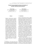
3.4.6.3 A Capability Network for Locomotion
The capability network shows how more complex behaviors depend on more basic
ones and finally on the actuators available. The timing (temporal sequencing) of
their activation has to be learned by testing and corresponding feedback of errors
occurring in the real world. Figure 3.28 shows the capability network for locomo-
tion of a wheeled ground vehicle. Note that some of the parameters determining the
trigger point for activation depend on visual perception and on other measurement
values. The challenges of system integration will be discussed in later chapters af-
ter the aspects of knowledge representation have been discussed.
Figure 3.28. Network of behavioral capabilities of a road vehicle: Longitudinal
and lateral control is fully separated only on the hardware level with three actua-
tors; many basic skills are realized by diverse parameterized feed-forward and
feedback control schemes. On the upper level, abstract schematic capabilities as
triggered from “central decision” are shown [Maurer 2000, Siedersberger 2004]
Brakes
Stand
still
Avoid
obstacle
Keep
speed
Constant
steering angle
Actuators
Skills
Schematic
capabilities
Halt
Approach
Steering rate
Ȝ-dot
Keep
course
Turn Ȝ
to zero
Drive
circular
arc
Keep
lane
Road
running
Waypoint
navigation
Stop in
front of
obstacle
Drive
at distance y
along guide
line
Turn to
heading
Turn Ȝ
to Ȝ
com
Accelerate
Decelerate
Keep
distance
Throttle
Longitudinal control Lateral control
3.6 Growth Potential of the Concept, Outlook 107
3.5 Situation Assessment and Decision-Making
Subjects differ from objects (proper) in that they have perceptual impressions from
the environment and the capability of decision-making with respect to their control
options. For subjects, a control term appears in the differential equation constraints
on their motion activities, which allows them to influence their motion; this makes
subjects basically different from objects.
If decisions on control selection are not implicitly given in the code implement-
ing subject behavior, but may be made according to some explicit goal criteria,
something like free will occurs in the behavior decision process of the subject. Be-
cause of the fundamentally new properties of subjects, these require separate meth-
ods for knowledge representation and for combining this knowledge with actual
perception to achieve their goals in an optimal fashion (however defined). The col-
lection of all facts of relevance for decision-making is called the situation. It is es-
pecially difficult if other subjects, who also may behave at will to achieve their
goals, form part of this process; these behaviors are unknown, usually, but may be
guessed sometimes from reasoning as for own decision-making.
Some expectations for future behavior of other subjects can be derived from try-
ing to understand the situation as it might look for oneself in the situation supposed
to be given for the other subject. At the moment, this is beyond the actual state of
the art of autonomous systems. But the methods under development for the sub-
ject’s decision-making will open up this avenue. In the long run, capabilities of
situation assessment of other subjects may be a decisive factor in the development
of really intelligent systems. Subjects may group together, striving for common
goals; this interesting field of group behavior taking real-world constraints into ac-
count is even further out in the future than individual behavior. But there is no
doubt that the methods will become available in the long run.
3.6 Growth Potential of the Concept, Outlook
The concept of subjects characterized by their capabilities in sensory perception, in
data processing (taking large knowledge bases for object/subject recognition and
situation assessment into account), in decision-making and planning as well as in
behavior generation is very general. Through an explicit representation of these ca-
pabilities, avenues for developing autonomous agents with new mental capabilities
of learning and cooperation in teams may open up. In preparation for this long-
term goal, representing humans with all their diverse capabilities in this framework
should be a good exercise. This is especially valuable for mixed teams of humans
and autonomous vehicles as well as for generating intelligent behavior of these ve-
hicles in environments abounding with activities of humans, which will be the
standard case in traffic situations.
In road traffic, other subjects frequently encountered (at least in rural environ-
ments) beside humans are four-legged animals of different sizes: horses, cattle,
3 Subjects and Subject Classes
108
sheep, goats, deer, dogs, cats, etc.; birds and poultry are two-legged animals, many
of which are able to fly.
Because of the eminent importance of humans and four-legged animals in any
kind of road traffic, autonomous vehicles should be able to understand the motion
capabilities of these living beings in the long run. This is out into the future right
now; the final section of this chapter shows an approach and first results developed
in the early 1990s for recognition of humans. This field has seen many activities
since the early work of
Hogg (1984) in the meantime and has grown to a special
area in technical vision; two recent papers with application to road traffic are [Ber-
tozzi et al. 2004; Franke et al. 2005]
3.6.1 Simple Model of Human Body as Traffic Participant
Elaborate models for the motion ca-
pabilities of human bodies are avail-
able in different disciplines of physi-
ology, sports, and computer
animation
[Alexander 1984; Bruderlin,
Calvert 1989; Kroemer 1988]. Humans
as traffic participants with the behav-
ioral modes of walking, running, rid-
ing bicycles or motor bikes as well as
modes for transmitting information
by waving their arms, possibly with
additional instruments, show a much
reduced set of stereotypical move-
ments.
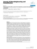
Kinzel (1994a, b), therefore, se-
lected the articulated body model
shown in Figure 3.29 to represent
humans in traffic activities in connec-
tion with the 4-D approach to dy-
namic vision. Visual recognition of
moving humans becomes especially
difficult due to the vast variety of
clothing encountered and of objects
carried. For normal Western style
clothing the cyclic activities of extremities are characteristic of humans moving.
Motion of limbs should be separated from body motion since they behave in dif-
ferent modes and at different eigenfrequencies, usually.
Head
(with neck)
0, 1
upper
arms
1
2
0
3
8
9
10
2, 3
lower
arms
upper
torso
lower
0, 1
shoulders
2, 3
elbows
12 waist
6, 7
hips
(13 neck)
0
1
23
4
5
67
12
4
5
6
7
4, 5
upper
legs
6, 7
lower
legs
Body segments
4, 5
hands
8, 9 knees
10, 11
feet
joints
8
9
10 11
Figure 3.29. Simple generic model for hu-
man shape with 22 degrees of freedom, af-
ter [Kinzel 1994]
Limbs tend to be used in typical cyclic motion, while the body moves more
steadily. The rotational movements of limbs may be in the same or in opposite di-
rection depending on the style and the phase of grasping or running.
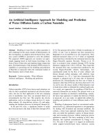
Figure 3.30 shows early results achieved with the lower part of the body model
from Figure 3.29; cyclic motion of the upper leg (hip angle, amplitude § 60°, upper
graph) and the lower leg (knee angle, amplitude § 100°, bottom graph) has been
recognized roughly in a computer simulation with real-time image sequence
3.6 Growth Potential of the Concept, Outlook 109
Fig. 3.31. Quantitative recognition of motion parameters of a human leg while
running: simulation with real image sequence processing (after [Kinzel 1994]).
Figure 3.30. Quantitative recognition of motion parameters of a human
leg while running: simulation with real image sequence processing, after
[Kinzel 1994].
evaluation and tracking. At that time, microprocessor resources were not sufficient
to do this onboard a car in real time (at least a factor of 5 was missing). In the
meantime, computing power has increased by more than two orders of magnitude
per processor, and human gesture recognition has attracted quite a bit of attention.
Also the wide-spread activities in computer animation with humanoid robots, and
especially the demanding challenge of the humanoid robo-cup league have ad-
vanced this field considerably, lately.
From the field last-mentioned and from analysis of sports as well as dancing ac-
tivities there will be a pressure towards automatically recognizing human (-oid)
motion. This field can be considered developing on its own; application within
semi-autonomous road or autonomous ground vehicles will be more or less a side
product. The knowledge base for these application areas of ground vehicles has to
be developed as a specific effort, however. In case of construction sites or accident
areas with human traffic regulation, future (semi-) autonomous vehicles should
3 Subjects and Subject Classes
110
also have the capability of proper understanding of regulatory arm gestures and of
proper behavior in these unusual situations. Recognizing grown-up people and
children wearing various clothing and riding bicycle or carrying bulky loads will
remain a challenging task.
3.6.2 Ground Animals and Birds
Beside humans, two superclasses of other animals play a role in rural traffic: Four-
legged animals of various sizes and with various styles of running, and birds (from
crows, hen, geese, turkeys, to ostrich), most of which can fly and run or hop on the
ground. This wide field of subjects has hardly been touched for technical vision
systems. In principle, there is no basic challenge for successful application of the
4-D approach. In practice, however, a huge volume of work lies ahead until techni-
cal vision systems will perceive animals reliably.
4 Application Domains, Missions, and Situations
In the previous chapters, the basic tools have been treated for representing objects
and subjects with homogeneous coordinates in a framework of the real 3-D world
and with spatiotemporal models for their motion. Their application in combination
with procedural computing methods will be the subject of Chapters 5 and 6. The
result will be an estimated state of single objects/subjects for the point “here and
now” during the visual observation process. These methods can be applied multiple
times in parallel to n objects in different image regions representing different spa-
tial angles of the world around the set of cameras.
Vision is not supposed to be a separate exercise of its own but to serve some
purpose in a task or mission context of an acting individual (subject). For deeper
understanding of what is being seen and perceived, the goals of egomotion and of
other moving subjects as well as the future trajectories of objects tracked should be
known, at least vaguely. Since there is no information exchange between oneself
and other subjects, usually, their future behavior can only be hypothesized based
on the situation given and the behavioral capabilities of the subjects observed.
However, out of the set of all objects and subjects perceived in parallel, generally
only a few are of direct relevance to their own plans of locomotion.
To be efficient in perceiving the environment, special attention and thus percep-
tual resources and computing power for understanding should be concentrated on
the most important objects/subjects. The knowledge needed for this decision is
quite different from that one needed for visual object and state recognition. The de-
cision has to take into account the mission plan and the likely behavior of other
subjects nearby as well as the general environmental conditions (like quality of
visual perception, weather conditions and likely friction coefficient for maneuver-
ing, as well as surface structure). In addition, the sets of rules for traffic regulation
valid in the part of the world, where the vehicle is in operation, have to be taken
into account.
4.1 Structuring of Application Domains
To survey where the small regime, onto which the rest of the book will be concen-
trating, fits in the overall picture, first (contributions to) a loosely defined ontology
for ground vehicles will be given. Appendix A shows a structured proposal which,
of course, is only one of many possible approaches. Here, only some aspects of
certain missions and application domains are discussed to motivate the items se-
4 Application Domains, Missions, and Situations
112
lected for presentation in this book. An all-encompassing and complete ontology
for ground vehicles would be desirable but has not yet been assembled in the past.
From the general environmental conditions grouped under A.1, up to now only
a few have been perceived explicitly by sensing, relying on the human operator to
take care for the rest. More autonomous systems have to have perceptual capabili-
ties and knowledge bases available to be able to recognize more of them by them-
selves. Contrary to humans, intelligent vehicles will have much more extended ac-
cess to satellite navigation (such as GPS now or Galileo in the future). In
combination with digital maps and geodetic information systems, this will allow
them improved mission planning and global orientation.
Obstacle detection both on roads and in cross-country driving has to be per-
formed by local perception since temporal changes are too fast, in general, to be re-
liably represented in databases; this will presumably also be the fact in the future.
In cross-country driving, beside the vertical surface profiles in the planned tracks
for the wheels, the support qualities of the ground for wheels and tracks also have
to be estimated from visual appearance. This is a very difficult task, and decisions
should always be on the safe side (avoid entering uncertain regions).
Representing national traffic rules and regulations (Appendix A.1.1) is a
straightforward task; their ranges of validity (national boundaries) have to be
stored in the corresponding databases. One of the most important facts is the gen-
eral rule of right- or left-hand traffic. Only a few traffic signs like stop and one-way
are globally valid. With speed signs (usually a number on a white field in a red cir-
cle) the corresponding dimension has to be inferred from the country one is in
(km/h in continental Europe or mph in the United Kingdom or the United States,
etc.).
Lighting conditions (Appendix A.1.2) affect visual perception directly. The dy-
namic range of light intensity in bright sunshine with snow and harsh shadows on
dark ground can be extremely large (more than six orders of magnitude may be en-
countered). Special high-dynamic-range cameras (HDRC) have been developed to
cope with the situation. The development is still going on, and one has to find the
right compromise in the price-performance trade-off. To perceive the actual situa-
tion correctly, representing the recent time history of lighting conditions and of po-
tential disturbances from the environment may help. Weather conditions (e.g., blue
skies) and time of day in connection with the set of buildings in the vicinity of the
trajectory planned (tunnel, underpass, tall houses, etc.) may allow us to estimate
expected changes which can be counteracted by adjusting camera parameters or
viewing directions. The most pleasant weather condition for vision is an overcast
sky without precipitation.
In normal visibility, contrasts in the scene are usually good. Under foggy condi-
tions, contrasts tend to disappear with increasing distance. The same is true at dusk
or dawn when the light intensity level is low. Features linked to intensity gradients
tend to become unreliable under these conditions. To better understand results in
state estimation of other objects from image sequences (Chapters 5 and 6), it is
therefore advantageous to monitor average image intensities as well as maximal
and minimal intensity gradients. This may be done over entire images, but comput-
ing these characteristic values for certain image regions in parallel (such as sky or
larger shaded regions) gives more precise results.
4.1 Structuring of Application Domains 113
It is recommended to have a steady representation available of intensity statis-
tics and their trends in the image sequence: Averages and variances of maximum
and minimum image intensities and of maximum and minimum intensity gradients
in representative regions. When surfaces are wet and the sun comes out, light re-
flections may lead to highlights. Water surfaces (like puddles) rippled by wind may
exhibit relatively large glaring regions which have to be excluded from image in-
terpretation for meaningful results. Driving toward a low standing sun under these
conditions can make vision impossible. When there are multiple light sources like
at night in an urban area, regions with stable visual features have to be found al-
lowing tracking and orientation by avoiding highlighted regions.
Headlights of other vehicles may also become hard to deal with in rainy condi-
tions. Backlights and stoplights when braking are relatively easy to handle but re-
quire color cameras for proper recognition. In RGB-color representation, stop
lights are most efficiently found in the R-image, while flashing blue lights on vehi-
cles for ambulance or police cars are most easily detected in the B-channel. Yellow
or orange lights for signaling intentions (turn direction indicators) require evalua-
tion of several RGB channels or just the intensity signal. Stationary flashing lights
at construction sites (light sequencing, looking like a hopping light) for indication
of an unusual traffic direction require good temporal resolution and correlation
with subject vehicle perturbations to be perceived correctly.
Recognition of weather conditions (Appendix A.1.3) is especially important
when they affect the interaction of the vehicle with the ground (acceleration, decel-
eration through friction between tires and surface material). Recognizing and ad-
justing behavior to rain, hail, and snow conditions may prevent accidents by cau-
tious driving. Slush and loose or wet dirt or gravel on the road may have similar
effects and should thus be recognized. Heavy winds and gusts can have a direct ef-
fect on driving stability; however, they are not directly visible but only by secon-
dary effects like dust or leaves whirling up or by moving grass surfaces and plants
or branches of trees. Advanced vision systems should be able to perceive these
weather conditions (maybe supported by inertial sensors directly feeling the accel-
erations on the body). Recognizing fine shades of texture may be a capability for
achieving this; at present, this is beyond the performance level of microprocessors
available at low cost, but the next decade may open up this avenue.
Roadway recognition (Appendix A.2) has been developed to a reasonable state
since recursive estimation techniques and differential geometry descriptions have
been introduced two decades ago. For freeways and other well-kept, high-speed
roads (Appendices A.2.1 and A.2.2), lane and road recognition can be considered
state of the art. Additional developments are still required for surface state recogni-
tion, for understanding the semantics of lane markings, arrows, and other lines
painted on the road as well as detailed perception of the infrastructure along the
road. This concerns repeating poles with different reflecting lights on both sides of
the roadway, the meaning of which may differ from one country to the next, and
guiderails on road shoulders and many different kinds of traffic and navigation
signs which have to be distinguished from advertisements. On these types of roads
there is only unidirectional traffic (one-way), usually, and navigation has to be
done by proper lane selection.
4 Application Domains, Missions, and Situations
114
On ordinary state roads with two-way traffic (Appendix A.2.3) the perceptual
capabilities required are much more demanding. Checking free lanes for passing
has to take oncoming traffic with high speed differences between vehicles and the
type of central lane markings into account. With speeds allowed of up to 100 km/h
in each direction, relative speed can be close to 60 m/s (or 2.4 m per video cycle of
40 ms). A 4-second passing maneuver thus requires about 250 m look-ahead range,
way beyond what is found in most of today’s vision systems. With the resolution
required for object recognition and the perturbation level in pitch due to nonflat
ground, inertial stabilization of gaze direction seems mandatory.
These types of roads may be much less well kept. Lane markings may be re-
duced to a central line indicating by its type whether passing is allowed (dashed
line) or not (solid line). To the sides of the road, there may be potholes to be
avoided; sometimes these may be found even on the road itself.
On all of these types of road, for short periods after (re-) construction there may
be no lane markings at all. In these cases, vehicles and drivers have to orient them-
selves according to road width and to the distance from “their” side of the sealed
surface. “Migrating construction sites” like for lane marking may be present and
have to be dealt with properly. The same is true for maintenance work or for grass
cutting in the summer.
Unmarked country roads (Appendix A.2.4) are usually narrow, and oncoming
traffic may require slowing down and touching the road shoulders with their outer
wheels. The road surface may not be well kept, with patches of dirt and high-
spatial frequency surface perturbations. The most demanding item, however, may
be the many different kinds of subjects on the road: People and children walking,
running and bicycling, carrying different types of loads or guarding animals. Wild
animals range from hares to deer (even moose in northern countries) and birds
feeding on cadavers.
On unsealed roads (Appendix A.2.5) where speed driven is much slower, usu-
ally, in addition to the items mentioned above, the vertical surface structure be-
comes of increasing interest due to its unstable nature. Tracks impressed into the
surface by heavily loaded vehicles can easily develop, and the likelihood of pot-
holes (even large ones into which wheels of usual size will fit) requires stereovi-
sion for recognition, probably with sequential view fixation on especially interest-
ing areas.
Driving cross-country, tracks (Appendix A.2.6) can alleviate the task in that
they show where the ground is sufficiently solid to support a vehicle. However,
due to non-homogeneous ground properties, vertical curvature profiles of high spa-
tial frequency may have developed and have to be recognized to adjust speed so
that the vehicle is not bounced around losing ground contact. After a period of rain
when the surface tends to be softer than usual, it has to be checked whether the
tracks are not so deep that the vehicle touches the ground with its body when the
wheels sink into the track. Especially, tracks filled with water pose a difficult chal-
lenge for decision-making.
In Appendix A.2.7, all infrastructure items for all types of roads are collected to
show the gamut of figures and objects which a powerful vision system for traffic
application should be able to recognize. Some of these are, of course, specific to
certain regions of the world (or countries). There have to be corresponding data
4.1 Structuring of Application Domains 115
bases and algorithms for recognizing these items; they have to be swapped when
entering a zone with new regulations.
In section Appendix A.3 the different types of vehicles are listed. They have to
be recognized and treated according to their form (shape), appearance and function
of the vehicle (Appendix A.4). This type of structuring may not seem systematic at
first glance. There is, of course, one column like A.4 for each type of vehicle under
A.3. Since this book concentrates on the most common wheeled vehicles (cars and
trucks), only these types are discussed in more detail here. Geometric size and 3-D
shape (Appendix A.4.1) have been treated to some extent in Section 2.2.3 and will
be revisited for recognition in Chapters 7 to 10.
Subpart hierarchies (Appendix A.4.2) are only partially needed for vehicles
driving, but when standing, open doors and hoods may yield quite different ap-
pearances of the same vehicle. The property of glass with respect to mirroring of
light rays has a fundamental effect on features detected in these regions. Driving
through an environment with tall buildings and trees at the side or with branches
partially over the road may lead to strongly varying features on the glass surfaces
of the vehicle, which have nothing to do with the vehicle itself. These regions
should, therefore, be discarded for vehicle recognition, in general. On the other
hand, with low light levels in the environment, the glass surfaces of the lighting
elements on the front and rear of the vehicle (or even highlights on windscreens)
may be the only parts discernible well and moving in conjunction; under these en-
vironmental conditions, these groups are sufficient indication for assuming a vehi-
cle at the location observed.
Variability of image shape over time depending on the 3-D aspect conditions of
the 3-D object “vehicle” (Appendix A.3) is important knowledge for recognizing
and tracking vehicles. When machine vision was started in the second half of the
last century, some researchers called the appearance or disappearance of features
due to self-occlusion a “catastrophic event” because the structure of their (insuffi-
cient) algorithm with fixed feature arrangements changed. In the 4-D approach
where objects and aspect conditions are represented as in reality and where tempo-
ral changes also are systematically represented by motion models, there is nothing
exciting with the appearance of new or disappearance of previously stable features.
It has been found rather early that whenever the aspect conditions bring two fea-
tures close to each other so that they may be confused (wrong feature correspon-
dence), it is better to discard these features altogether and to try to find unambigu-
ous ones
[Wünsche 1987]. The recursive estimation process to be discussed in
Chapter 6 will be perturbed by wrong feature correspondence to a larger extent
than by using slightly less well-suited, but unambiguous features. Grouping re-
gimes of aspect conditions with the same highly recognizable set of features into
classes is important knowledge for hypothesis generation and tracking of objects.
When detecting new feature sets in a task domain, it may be necessary to start
more than one object hypothesis for fast recognition of the object observed. Such
4-D object hypotheses allow predicting other features which should be easily visi-
ble; in case they cannot be found in the next few images, the hypothesis can be dis-
carded immediately. An early jump to several 4-D hypotheses thus has advantages
over too many feature combinations before daring an object hypothesis (known as
a combinatorial explosion in the vision literature).
4 Application Domains, Missions, and Situations
116
Photometric appearance (Appendix A.4.4) can help in connection with the as-
pect conditions to find out the proper hypothesis. Intensity and color shading as
well as high resolution in texture discrimination contribute positively to eliminat-
ing false object hypotheses. Computing power and algorithms are becoming avail-
able now for using these region-based features efficiently. The last four sections
discussed are concerned with single object (vehicle) recognition based on image
sequence analysis. In our approach, this is done by specialist processes for certain
object classes (roads and lanes, other vehicles, landmarks, etc.).
When it comes to understanding the semantics of processes observed, the func-
tionality aspects (Appendix A.4.5) prevail. For proper recognition, observations
have to be based on spatially and temporally more extended representation. Trying
to do this with data-intensive images is not yet possible today, and maybe even not
desirable in the long run for data efficiency and corresponding delay times in-
volved. For this reason, the results of perceiving single objects (subjects) “here and
now” directly from image sequence analysis with spatiotemporal models are col-
lected in a “dynamic object database” (DOB) in symbolic form. Objects and sub-
jects are represented as members of special classes with an identification number,
their time of appearance, and their relative state defined by homogeneous coordi-
nates, as discussed in Section 2.1.1. Together with the algorithms for homogeneous
coordinate transformations and shape computation, this represents a very compact
but precise state and shape description. Data volumes required are decreased by
two to three orders of magnitude (KB instead of MB). Time histories of state vari-
ables are thus manageable for several (the most important) objects/subjects ob-
served.
For subjects, this allows recognizing and understanding maneuvers and behav-
iors of which one knows members of this type of subject class are capable (Appen-
dix A.4.6). Explicit representations of perceptual and behavioral capabilities of
subjects are a precondition for this performance level. Tables 3.1 and 3.3 list the
most essential capabilities and behavioral modes needed for road traffic partici-
pants. Based on data in the ring-buffer of the DOB for each subject observed, this
background knowledge now allows guessing the intentions of the other subject.
This qualitatively new information may additionally be stored in special slots of
the subject’s representation. Extended observations and comparisons to standards
for decisions–making and behavior realization now allows attributing additional
characteristic properties to the subject observed. Together with the methods avail-
able for predicting movements into the future (fast-in-advance simulation), this al-
lows predicting the likely movements of the other subject; both results can be
compared and assessed for dangerous situations encountered. Thus, real-time vi-
sion as propagated here is an animation process with several individuals based on
previous (actual) observations and inferences from a knowledge base of their inten-
tions (expected behavior).
This demanding process cannot be performed for all subjects in sight but is con-
fined to the most relevant ones nearby. Selecting and perceiving these most rele-
vant subjects correctly and focusing attention on them is one of the decisive tasks
to be performed steadily. The judgment, which subject is most relevant, also de-
pends on the task to be performed. When just cruising with ample time available,
the situation is different from the same cruising state in the leftmost of three lanes,
4.2 Goals and Their Relations to Capabilities 117
but an exit at the right is to be taken in the near future. On a state road, cruising in
the rightmost lane but having to take a turnoff to the left from the leftmost lane
yields a similar situation. So the situation is not just given by the geometric ar-
rangement of objects and subjects but also depends on the task domain and on the
intentions to be realized.
Making predictions for the behavior of other subjects is a difficult task, espe-
cially when their perceptual capabilities (Appendix A.4.7) and those for planning
and decision-making (Appendix A.4.8) are not known. This may be the case with
respect to animals in unknown environments. These topics (Appendix A.6) and the
well-known but very complex appearance and behavior of humans (Appendix A.5)
are not treated here.
Appendix A.7 is intended to clarify some notions in vehicle and traffic control
for which different professional communities have developed different terminol-
ogies. (Unfortunately, it cannot be assumed that, for example, the terms “dynamic
system” or “state” will be understood with the same meaning by one person from
the computer science and a second one from the control engineering communities.)
4.2 Goals and Their Relations to Capabilities
To perform a mission efficiently under perturbations, both the goal of the mission
together with some quality criteria for judging mission performance and the capa-
bilities needed to achieve them have to be known.
The main goal of road vehicle traffic is to transport humans or goods from point
A to point B safely and reliably, observing some side constraints and maybe some
optimization criteria. A smooth ride with low values of the time integrals of (longi-
tudinal and lateral) acceleration magnitudes (absolute values) is the normal way of
driving (avoiding hectic control inputs). For special missions, e.g., on ambulance
or touring sightseers, these integrals should be minimized.
An extreme type of mission is racing, exploiting vehicle capabilities to the ut-
most and probably reducing safety by taking more risks. Minimal fuel consumption
is the other extreme where travel time is of almost no concern.
Safety and collision avoidance even under adverse conditions and in totally un-
expected situations is the most predominant aspect of vehicle guidance. Driving at
lower speed very often increases safety; however, on high-speed roads during
heavy traffic, it can sometimes worsen safety. Going downhill, the additional thrust
from gravity has to be taken into account which may increase braking distance
considerably. When entering a crossroad or when starting a passing maneuver on a
road with two-way traffic, estimation of the speed of other vehicles has to be done
with special care, and an additional safety margin for estimation errors should be
allowed. Here, it is important that the acceleration capabilities of the subject vehi-
cle under the given conditions (actual mass, friction coefficient, power reserves)
are well known and sufficient.
When passing on high-speed roads with multiple lanes, other vehicles in the
convoy being passed sometimes start changing into your lane at short distances,
4 Application Domains, Missions, and Situations
118
without using indication signs (blinker); even these critical situations not conform-
ing to standard behavior have to be coped with successfully.
4.3 Situations as Precise Decision Scenarios
The definition for “situation” used here is the following: A situation encompasses
all aspects of relevance for decision-making in a given scenario and mission con-
text. This includes environmental conditions affecting perception and limit values
for control application (such as wheel to ground friction coefficients) as well as the
set of traffic regulations actually valid that have been announced by traffic signs
(maximum speed allowed, passing prohibited, etc.). With respect to other ob-
jects/subjects, a situation is not characterized by a single relation to one other unit
but to the total number of objects of relevance. Which of those detected and
tracked are relevant is a difficult decision. Even the selected regions of special at-
tention are of importance. The objects/subjects of relevance are not necessarily the
nearest ones; for example, driving at higher speed, some event happening at a far-
ther look-ahead distance than the two preceding vehicles may be of importance: A
patch of dense fog or a front of heavy rain or snow can be detected reliably at rela-
tively long distance. One should start reacting to these signs at a safe distance ac-
cording to independent judgment and not only when the preceding vehicles start
their reactions.
Some situational aspects can be taken into account during mission planning. For
example, driving on roads heading into the low-standing sun at morning or evening
should be avoided by proper selection of travel time. Traffic congestion during
rush hour also may be avoided by proper timing. Otherwise, the driver/autonomous
vehicle has to perceive the indicators for situational aspects, and from a knowledge
base, the proper behavior has to be selected. The three components required to per-
form this reliably are discussed in the sections below: Environmental background,
objects/subjects of relevance, and the rule systems for decision-making. Beside the
rules for handling planned missions, another set of perceptual events has to be
monitored which may require another set of rules to be handled for selecting
proper reactions to these events.
4.3.1 Environmental Background
This has not received sufficient attention in the recent past since, at first, the basic
capabilities of perceiving roads and lanes as well as other vehicles had to be dem-
onstrated. Computing power for including at least some basic aspects of environ-
mental conditions at reasonable costs is now coming along. In Section 4.1 and Ap-
pendix A.1.2 (lighting conditions)/A.1.3 (weather conditions), some aspects have
already been mentioned. Since these environmental conditions change rather
slowly, they may be perceived at a low rate (in the range of seconds to minutes).
An economical way to achieve this may be to allot remaining processing time per
video cycle of otherwise dedicated image processing computers to this “environ-
4.3 Situations as Precise Decision Scenarios 119
mental processing” algorithm. These low-frequency results should be made avail-
able to all other processes by providing special slots in the DOB and depositing the
values with proper time stamps. The situation assessment algorithm has to check
these values for decision-making regularly.
The specialist processes for visual perception should also have a look at them to
adjust parameters in their algorithms for improving results. In the long run, a direct
feedback component for learning may be derived. Perceiving weather conditions
through textures may be very computer-intensive; once the other basic perception
tasks for road and other vehicles run sufficiently reliable, additional computing
power becoming available may be devoted to this task, which again can run at a
very low rate. Building up a knowledge base for the inference from distributed tex-
tures in the images toward environmental conditions will require a large effort.
This includes transitions in behavior required for safe mission performance.
4.3.2 Objects/Subjects of Relevance
A first essential step is to direct attention (by gaze control and corresponding im-
age evaluation) to the proper environmental regions, depending on the mission
element being performed. This is, of course, different for simple roadrunning, for
preparing lane changes, or for performing a turnoff maneuver. Turning off to the
left on roads with oncoming (right-hand) traffic is especially demanding since their
lane has to be crossed.
Driving in urban environments with right-of-way for vehicles on crossroads
coming from the right also requires special attention (looking into the road). Enter-
ing traffic circles requires checking traffic in the circle, because these vehicles
have the right-of-way. Especially difficult are 4-way-stops in use in some coun-
tries; here the right-of-way depends on the time of reaching the stop–lines on all
four incoming roads.
Humans may be walking on roads through populated areas and in stop-and-go
traffic. On state, urban and minor roads, humans may ride bicycles, may be roller
skating, jogging, walking, or leisurely strolling. Children may be playing on the
road. Recognizing these situations with their semantic context is actually out of
range for machine vision. However, detecting and recognizing moving volumes
(partially) filled with massive bodies is in the making and will become available
soon for real-time application. Avoiding these areas with a relatively large safety
margin may be sufficient for driver assistance and even for autonomous driving.
Some nice results for assistance in recognizing humans crossing in front of the ve-
hicle (walking or biking) have been achieved in the framework of the project “In-
vent”
[Franke et al. 2005].
With respect to animals on the road, there are no additional principal difficulties
for perception except the perhaps erratic motion behavior some of these animals
may show. Birds can both move on the ground and lift off for flying; in the transi-
tion period there are considerable changes in their appearance. Both their shapes
and the motion characteristics of their limbs and wings will change to a large ex-
tent.
4 Application Domains, Missions, and Situations
120
4.3.3 Rule Systems for Decision-Making
Perception systems for driver assistance or for autonomous vehicle guidance will
need very similar sets of rules for the perception part (maybe specialized to some
task of special interest). Once sufficient computing power for visual scene analysis
and understanding is affordable, the information anyway in the image streams can
be fully exploited, since both kinds of application will gain from deeper under-
standing of motion processes observed. This tends to favor three separate rule
bases in a modular system: The first one for perception (control of gaze direction
and attention) has to be available for both types of systems. In addition, there have
to be two different sets, one for assistance systems and one for autonomous driving
(locomotion, see Chapters 13 and 14).
Since knowledge components for these task domains may differ widely, they
will probably be developed by different communities. For driver assistance sys-
tems, the human-machine-interface with many psychological aspects poses a host
of challenges and interface parameters. Especially, if the driver is in charge of all
safety aspects for liability reasons, the choice of interface (audio, visual, or tactile)
and the ways of implementing the warnings are crucial. Quite a bit of effort is go-
ing into these questions in industry at present (see the proceedings of the yearly In-
ternational Symposium on Intelligent Vehicles
[Masaki 1992–1999]). Tactile inputs
may even include motion control of the whole vehicle. Horseback riders develop a
fine feeling for slight reactions of the animal to its own perceptions. The question
is whether similar types of special motion are useful for the vehicle to direct atten-
tion of the driver to some event the vehicle has noticed. Introducing vibrations at
the proper side of the driver seat when the vehicle approaches one of the two lane
markers left or right too closely is a first step done in this direction
[Citroen 2004].
First correcting reactions in the safe direction or slight resistance to maneuvers in-
tended may be further steps; because of the varying reactions from the population
of drivers, finding the proper parameters is a delicate challenge.
For autonomous driving, the relatively simple task is to find the solution when
to use which maneuvers or/and feedback algorithms with which set of optimal pa-
rameters. Monitoring the process initiated is mandatory for checking actual per-
formance achieved in contrast to the nominal one expected. Statistics should be
kept on the behavior observed, for learning reasons.
In case some unexpected “event” occurs (like a vehicle changing into your lane
immediately in front of you without giving signs), this situation has to be handled
by a transition in behavior; reducing throttle setting or hitting the brakes has to be
the solution in the example given. These types of transitions in behavior are coded
in extended state charts
[Harel 1987; Maurer 2000]; actual implementation and results
will be discussed in later chapters. The development of these algorithms and their
tuning, taking delay times of the hardware involved into account is a challenging
engineering task requiring quite a bit of effort.
Note that in the solution chosen here, the rule base for decision–making does
not contain the control output for the maneuvers but only the conditions, when to
switch from one maneuver or driving state to another one. Control implementation
is done at a lower level with processors closer to the actuators (see Section 3.4.4).
4.4 List of Mission Elements 121
4.4 List of Mission Elements
Planning entire missions is usually done before the start of the mission. During this
process, the mission is broken down into mission elements which can be performed
with the same set of behavioral modes. The list of mission elements is the task de-
scription for the process governing situation assessment and behavior decision. It
also calls for implementation of behavioral capabilities actually available. In case
some nominal behavioral capability is actually not available because of some
hardware failure, this fact is detected by this process (by polling corresponding bits
in the hardware monitoring system), and mission replanning has to take this new
situation into account.
The duration of mission elements may be given by local timescales or by some
outside event; for example, lane following should be done until a certain geo-
graphical position has been reached at which a turnoff at an intersection has to be
taken. This is independent of the time it took to get there.
During these mission elements defined by nominal “strategic” aspects of mis-
sion performance, tactical deviations from the nominal plan are allowed such as
lane changing for passing slower traffic or convoy driving at speeds lower than
planned for the mission element. To compensate for the corresponding time losses,
the vehicle may increase travel speed for some period after passing the convoy (pa-
rameter adjustment)
[Gregor 2002; Hock 1994].
In the region of transition between two mission elements, the perception system
may be alerted to detect and localize the relative position so that a transient ma-
neuver can be started in time, taking time delays for implementation into account.
A typical example is when to start the steer rate maneuver for a turnoff onto a
crossroad. Sections 14.6.5 and 14.6.6 will discuss this maneuver as one important
element of mission performance as implemented on the test vehicle VaMoRs. Fig-
ure 14.15 shows the graphical visualization of the overall mission. The correspond-
ing list of mission elements (coarse resolution) is as follows:
1. Perform roadrunning from start till GPS signals the approach of a crossroad
onto which a turnoff to the left shall be made.
2. While approaching the crossroad, determine by active vision the precise width
and orientation of the cross road as well as the distance to the intersection.
3. Perform the turnoff to the left.
4. At a given GPS-waypoint on the road, leave the road at a right angle to the right
for cross-country driving.
5. Drive toward a sequence of landmarks (GPS-based); while driving, detect and
perceive negative obstacles (ditches) visually and avoid them through bypass-
ing on the most convenient side. [There is no one, actually in this part of the
mission.]
6. Visually detect and recognize a road being approached during cross-country
driving (point 6 in Figure 14.5). Estimate intersection angle, road width, and
distance to the road (continually while driving).
7. Turn onto road to the left from cross-country driving; adjust speed to surface
inclination encountered.
8. Perform roadrunning, recognizing crossroad as landmarks (points 6 to 8).
4 Application Domains, Missions, and Situations
122
9. Cross both intersections (T-junction left and right).
10. Leave road to the left at GPS-waypoint (9) for cross-country driving.
11. While driving toward a sequence of landmarks (GPS-based), detect and per-
ceive negative obstacles (ditches) visually and avoid them through bypassing
on the most convenient side. [In the case of Figure 14.15 there is one ditch on
trajectory-arc 10; it should be avoided by evading to the right. If a ditch is en-
countered, there is a new list of tasks to be performed in a similar manner for
this complex evasive maneuver consisting of several perceptual tasks and se-
quences of motion control.]
12. Finish mission at GPS-landmark X (in front of a road).
In driver assistance systems, similar mission elements exist, such as roadrunning
(with “lane departure warning”), convoy driving (with “adaptive cruise control”),
or “stop-and-go” traffic. The assistance functions can be switched on or off sepa-
rately by the human operator. A survey on this technology including the human-
machine-interface (HMI) may be found in
[Maurer, Stiller 2005].
5 Extraction of Visual Features
In Chapters 2 and 3, several essential relations among features appearing in images
and objects in the real world have been discussed. In addition, basic properties of
members of the classes “objects” and “subjects” have been touched upon to enable
efficient recognition from image sequences. Not only spatial shape but also motion
capabilities have been described as background for understanding image sequences
of high frequency (video rate). This complex task can be broken down into three
consecutive stages (levels), each requiring specialized knowledge with some over-
lap. Since the data streams required for analysis are quite different in these stages,
namely (1) whole images, (2) image regions, and (3) symbolic descriptions, they
should be organized in specific data bases.
The first stage is to discover the following items in the entire fields of view (im-
ages): (a) what are characteristic image parameters of influence for interpreting the
image stream, and (b) where are regions of special interest in the images?
The answer to question (a) has to be determined to tap background knowledge
which allows deeper understanding of the answers found under (b). Typical ques-
tions to be answered by the results to complex (a) are (1) What are the lowest and
the highest image intensities found in each image? It is not so much the value of a
single pixel of interest here [which might be an outlier (data error)] but of small lo-
cal groups of pixels, which can be trusted more. (2) What are the lowest and high-
est intensity gradients (again evaluated by receptive fields containing several pix-
els)? (3) Are these values drastically different in different parts of the images?
Here, an indication of special image regions such as ‘above and below the hori-
zon’, or ‘near a light source or further away from it’ may be of importance. (4) Are
there large regions with approximately homogeneous color or texture distribution
(representing areas in the world with specific vegetation or snow cover, etc.)? At
what distance are they perceived?
Usually, the answer to (b) will show up in collections of certain features. Which
features are good indicators for objects of interest is, of course, domain specific.
Therefore, the knowledge base for this stage 1 concentrates on types and classes of
image features for certain task domains and environmental conditions; this will be
treated in Section 5.1.
At this level, only feature data are to be computed as background material for
the higher levels, which try to associate environmental aspects with these data sets
by also referring to the mission performed and to knowledge about the environ-
ment, taking time of day and year into account.
In the second stage, the question is asked ‘What type of object is it, generating
the feature set detected’, and ‘what is its relative state at the present time’? Of
course, this can be answered for only one object/subject at one time by a single in-
5 Extraction of Visual Features
124
Figure 5.1. Structured knowledge base for three stages of visual dynamic scene under-
standing in expectation-based, multi-focal, saccadic (EMS) vision”
terpretation process. So, the amount of image data to be touched is reduced drasti-
cally, while background knowledge on the object/subject class allows asking spe-
cific questions in image interpretation with correspondingly tuned feature extrac-
tors. Continuity conditions over time play an important role in state estimation
from image data. In a complex scene, many of these questions have to be answered
in parallel during each video cycle. This can be achieved by time slicing attention
of a single processor/software combination or by operating with several or many
processors (maybe with special software packages) in parallel. Increasing comput-
ing power available per processor will shift the solution to the former layout. Over
the last decade, the number of processors in the vision systems of UniBwM has
been reduced by almost an order of magnitude (from 46 to 6) while at the same
time the performance level increased considerably. The knowledge bases for rec-
ognizing single objects/subjects and their motion over time will be treated in Chap-
ters 6 and 12.
Gaze
platform
‘
‘
MarVEye
MarVEye
’
’
Top-down
feature extraction
in specified fields of view;
find
‘
corresponding’
(groups of)
features on
objects tracked
;
4-D
recursive
state estimation
4
Tele
Wide
Wide
Behavior Decision
for
Gaze and
A
ttention;
Optimization of gaze
direction and -
sequencing;
G
aze C
ontrol
Feature data base (topologic?)
2
1- 3
a
7
Time histories of state variables
(for objects / subjects of special interest)
Scene tree representation of all objects tracked
(Homogeneous Coordinate Transformations)
Dynamic object database
(DOB, distributed system wide, time stamped)
Bottom-up
feature extraction in
large field of view (whole images);
detect ‘interesting’ (groups of)
features, feature flow;
(central)
stereo disparity map
What are
the
general
environ-
mental
conditions
?
Determine
charac-
teristic
Situational
features
L
e
v
e
l
1
L
e
v
e
l
2
Situation analysis
Which ones are the relevant
objects/subjects ?
Detect
maneuvers
of subjects,
intent recognition
,
predictions; check situation
with respect to own
mission plan and goals
.
6
L
e
v
e
l
3
gaze
control
1
5
Statistic
on
features
for
deter-
mining
situational
aspects
D
O
B
Recognize and
track
large
object
structures
nearby
3
D
F
B
5.1 Visual Features 125
The results of all of these single-object–recognition processes have to be pre-
sented to the situation assessment level in unified form so that relative motion be-
tween objects and movements of subjects can be appreciated on a larger spatial and
temporal scale. The dynamic object database (DOB) solves this task. On the situa-
tion level, working on huge volumes of image data is no longer possible. There-
fore, the DOB also serves the purpose of presenting the scene recognized in an ob-
ject-oriented, symbolic way. Figure 5.1 shows the three levels for image sequence
processing and understanding. The results of the right-hand branch from level 1 are
fed into this scheme to provide background information on the lighting and other
environmental conditions.
The situation to be assessed on the decision level has to include all of this and
the trajectory planned for the subject body in the near future. Both safety aspects
and mission goals have to be taken into account here; a selection has to be made
between more and less relevant objects/subjects by judging hazard potentials from
their trajectories/behaviors. This challenge will be discussed in Chapter 13. Figure
5.1 visualizing the stages mentioned for visual dynamic scene interpretation will be
discussed in more detail after the foundations for feature extraction and ob-
ject/subject recognition have been laid down.
5.1 Visual Features
The discussion of the topic of feature extraction will be done here in an exemplary
fashion only for road scenes. Other domains may require different feature sets;
however, edge and corner features are very robust types of features under a wide
range of varying lighting and aspect conditions in many domains. Additional fea-
ture sets are gray value or color blobs, certain intensity or color patterns, and tex-
tures. The latter cover a wide range; they are very computer-intensive, in general.
In biological vertebrate vision, edge features of different size and under different
orientations are one of the first stages of visual processing (in V1
[Hubel and Wiesel
1962]
). There are many algorithms available for extracting these features (see
[Duda, Hart 1973; Ballard, Brown 1982; Canny 1983; />Notes/bibliography/contents.html]
. A very efficient algorithm especially suited for
road-scene analysis has been developed by
Kuhnert (1988) and Mysliwetz (1990).
Search directions or patterns are also important for efficient feature extraction. A
version of this well-proven algorithm, the workhorse of the 4-D approach over two
decades, will be discussed in detail in Section 5.2. Computing power in the 1980s
did not allow more computer-intensive features for real-time applications at that
time. Now that four orders of magnitude in computing power per microprocessor
have been gained and are readily available, a more general feature extraction
method dubbed “UBM”, the basic layout of which has been developed by
Hof-
mann
(2004) and the author, will be discussed in Section 5.3. It unifies the extrac-
tion of the following features in a single pass: Nonplanar regions of the image in-
tensity function, linearly shaded blobs, edges of any orientation, and corners.
5 Extraction of Visual Features
126
5.1.1 Introduction to Feature Extraction
The amount of data collected by an imaging sensor is the same when looking at a
uniformly gray region or at a visually complex colored scene. However, the
amount of information perceived by an intelligent observer is considerably differ-
ent. A human would characterize the former case exhaustively by using just three
words: “uniformly gray”, and possibly a term specifying the gray tone (intensity).
The statement “uniformly” may be the result of rather involved low-level parallel
computations; but this high-level representational symbol in combination with the
intensity value contains all the information in the image. In contrast, if several ho-
mogeneously colored or textured subregions are being viewed, the borderlines be-
tween these regions and the specification of the color value per region contain all
the information about the scene (see Figure 5.2).
Instead of having to deal with all
the color values of all pixels, this
number of data may be considerably
reduced by just listing the coordinates
of the boundary elements; depending
on the size of the regions, this may be
orders of magnitude less data for the
same amount of information. This is
the reason that sketches of boundary
lines are so useful and widely spread.
Uniformly textured (gray)
Boundary curve
Uniformly white
Very often in images of the real
world, line elements change direction
smoothly over arc-length, except at
discrete points called “corners”. The direction change per unit arc-length is termed
curvature and is the basis for differential geometry
[Spivak 1970]. The differential
formulation of shapes is coordinate-free and does not depend on the position and
angular orientation of the object described. The same 2-D shape on different scales
can be described in curvature terms by the same function over arc length and one
scaling factor. Measurement of the tangent direction to a region, therefore, is a ba-
sic operation for efficient image processing. For measuring tangent directions pre-
cisely at a given scale, a sufficiently large environment of the tangent point has to
be taken into account to be precise as a function of scale level and to avoid “spuri-
ous details”
[Florack et al. 1992]. Direction coding over arc length is a common
means for shape description
[Freeman 1974; Marshall 1989].
Figure 5.2. Two homogeneous regions;
most information is in the boundary curve
Curvature coding over arc length is less widely spread. In
[Dickmanns 1985], an
approximate, general, efficient, coordinate-free 2-D shape description scheme in
differential-geometry terms has been given, based on local tangent direction meas-
urements relative to the chord line linking two consecutive boundary points with
limited changes in tangent direction (< 0.2 radians). It is equivalent to piecewise
third-order Hermite polynomial approximations based on boundary points and their
tangent directions.
However, sticking to the image plane for shape description of 3-D bodies in the
real world may not be the best procedure; rigid 3-D bodies and curves yield an in-
finite number of 2-D views by perspective mapping (at least theoretically), depend-
5.1 Visual Features 127
ing on the aspect conditions. The shape invariance in this case can be captured only
by using 3-D shape models and models for mapping by central projection. This ap-
proach is much better suited for visually recognizing the environment during ego–
motion and for tracking other (massive) objects over time, than for single snapshot
interpretation. This is true since massive bodies move smoothly over time, and in-
variance properties with respect to time, such as eigen–frequencies, damping, and
stereotypic motion characteristics (like style of walking), may be exploited as
knowledge about specific objects/subjects in the real world. Therefore, embedding
the image analysis task in a temporal continuum and exploiting known motion
characteristics in an object-oriented way will alleviate the image sequence interpre-
tation task (extended idea of gestalt). It requires, however, that the internal repre-
sentation be in four dimensions right from the beginning: in 3-D space and time for
single objects. This is the essence of the 4-D approach to dynamic machine vision
developed in the early 1980s
[Meissner, Dickmanns 1983; Dickmanns 1987; Wünsche
1987]
.
By embedding (a) simple feature extraction with linear edge elements, (b) re-
gions with linear shading models, and (c) horizontal and vertical image stripes into
this framework of spatio–temporal object orientation, these methods gain consid-
erably in power and useful range of application. By exploiting a knowledge base
on dynamic motion derived from previous experience in observing motion proc-
esses in 3-D space of specific 3-D objects carrying highly visible features on their
surface, scene understanding is considerably alleviated. Specific groups of linearly
extended edge feature sets and adjacent homogeneous areas of gray, color (or in
the future texture) values are interpreted as originating from these spatial objects
under specific aspect conditions. This background may also be one of the reasons,
beside their robustness to changing lighting conditions, that in highly developed
biological vision systems (like the mammalian ones) edge element operators
abound
[Hubel, Wiesel 1962; Koenderink, van Doorn 1990]. Without 3-D invariance
and without knowledge about motion processes and about perspective projection
(implicit or explicit), the situation would be quite different with respect to the use-
fulness of these operators.
The edge-based approach has an advantage over region-based approaches if in-
variance under varying lighting conditions is considered. Even though the intensi-
ties and color values may change differently with time in adjacent image regions,
the position of the boundaries between them does not, and the edge will remain
visible as the locus of highest intensity or color gradient. In natural environments,
changing lighting conditions are more the rule than an exception. Therefore, Sec-
tion 5.2 will be devoted to edge-based methods.
However, for robust interpretation of complex images, region-based image
evaluation is advantageous. Since today's processors do not allow full scale area-
based processing of images in real time, a compromise has to be sought. Some as-
pects of region-based image evaluation may be exploited by confining the regional
operations to the vicinity of edges. This is done in conjunction with the edge-based
approach, and it can be of help in establishing feature correspondence for object
recognition using a knowledge base and in detecting occlusions by other objects.
A second step toward including area-based information in the 4-D scheme under
the constraint of limited computing power is to confine the evaluation areas to
5 Extraction of Visual Features
128
stripes, whose orientation and width have to be chosen intelligently ad hoc, exploit-
ing known continuity conditions in space and time. These stripes will be condensed
to one-dimensional (averaged over the width of the stripes) representation vectors
by choosing proper schemes of symbolic descriptions for groups of pixel values in
the stripe direction.
Coming back to the difference between data and information, in knowledge-
based systems, there may be a large amount of information in relatively few data, if
these data allow a unique retrieval access to a knowledge base containing informa-
tion on the object recognized. This, in turn, may allow much more efficient recog-
nition and visual tracking of objects by attention focusing over time and in image
regions of special interest (window concept).
According to these considerations, the rest of Chapter 5 will be organized as fol-
lows: In Section 5.1.2, proper scaling of fields of view in multi-focal vision and in
selecting scales for templates is discussed. Section 5.2 deals with an efficient basic
edge feature extraction operator optimized for real-time image sequence under-
standing. In Sections 5.3, (2-D) region-based image evaluation is approached as a
sequence of one-dimensional image stripe evaluations with transition to symbolic
representations for alleviating data fusion between neighboring stripes and for im-
age interpretation. An efficient method with some characteristics of both previous
approaches is explained in Section 5.4; it represents a trade-off between accuracy
achievable in perception and computational expense.
Contrasting the feature extraction methods oriented towards single-object rec-
ognition, Section 5.5 gives an outlook on methods and characteristic descriptors for
recognizing general outdoor environments and situations. Computing power avail-
able in the past has not allowed applying this in real-time onboard vehicles; the
next decade should allow tackling this task for better and more robust scene under-
standing.
5.1.2 Fields of View, Multi-focal Vision, and Scales
In dealing with real-world tasks of surveillance and motion control very often cov-
erage of the environment with a large field of view is needed only nearby. For a
vehicle driving at finite speed, only objects within a small distal range will be of
interest for collision avoidance. When one is traveling at high speed, other low-
speed objects become of interest for collision avoidance only in a rather small an-
gular region around the subject’s velocity vector. [For several high-speed vehicles
interacting in the same space, special rules have to be established to handle the
situations, such as in air traffic control, where different altitudes are assigned to
airplanes depending on their heading angle (in discrete form by quadrants).]
Central projection is the basic physical process of imaging; depending on the
distal range of the object mapped into the image, this results in one pixel represent-
ing areas of different size on objects in the real world. Requiring a certain resolu-
tion normal to the optical axis for objects in the real world, therefore, requires
range-dependent focal lengths for the imaging system.
Biological systems have mastered this problem by providing different pixel and
receptive field sizes in the sensor hardware eye. In the foveal area designed for
5.1 Visual Features 129
long-range, high-resolution viewing, the density of sensor elements is very high; in
the peripheral areas added for large angular viewing range, element density is
small. By this combination, a large viewing range can be combined with high reso-
lution at least in some area with relatively moderate overall data rates. The area of
high resolution can be shifted by active viewing direction (gaze) control by both
the eye and the head.
In technical systems, since inexpensive sensors are available only with homo-
geneous pixel distributions, an equivalent mapping system is achieved by mount-
ing two or mores cameras with lenses of different focal lengths fixed relative to
each other on a platform. The advantage of a suite of sensors covering the same
part of the scenery is that this part is immediately available to the system in a mul-
ti-scale data set. If the ratio of the focal lengths is four, the image produced by the
shorter focal length represents (coarse) information on the second pyramid level of
the image taken with the higher resolution (larger focal length). This dual scale fac-
tor may sometimes be advantageous in real-time vision where time delays are criti-
cal. On one hand, efficient handling of objects requires that a sufficiently large
number of pixels be available on each object for recognition and identification; on
the other hand, if there are too many pixels on a single object, image processing
becomes too involved and slow.
As mentioned in the introduction, in complex scenes with many objects or with
some objects with a complex pattern of sub-objects, relying solely on edge features
may lead to difficulties and ambiguities. Combining the interpretation of edge fea-
tures with area-based features (average intensity, color, or texture) often allows
easy disambiguation. Figure 5.3 shows a case of efficient real-time image sequence
processing. Large homogeneous areas can be tracked by both edge features and re-
gion-based features. In the near range, the boundaries between the regions are not
sharp but fuzzy (strongly perturbed, unsealed country road with grass spreading
onto the road). For initialization from a normal driving situation, searching edges
with large receptive fields in most likely areas is very efficient.
The area-based method covering the entire image width would improve robust-
ness to road parameters other than expected, but would also be costly because of
Figure 5.3. Combining edge and area-based features for robust object detection and rec-
ognition. Near range: Only edge detection in regions and with parameters selected accord-
ing to a normal driving situation. Far range: Four stripes covering the entire width of the
image; determine steep edges and intensity plateaus (lower part) to discover road forks.