Electroactive Polymers for Robotic Applications - Kim & Tadokoro (Eds.) Part 5 doc
Bạn đang xem bản rút gọn của tài liệu. Xem và tải ngay bản đầy đủ của tài liệu tại đây (714.92 KB, 20 trang )
Robotic Applications of Artificial Muscle Actuators 73
l x
(a) Initial state
F
L
= F
R
Fix frame
Dielectric elastomer actuator
Elastic body
F
Maxwell
F
Maxwell
Original
length
Prestain
F
L
F
R
F
m
F
m
F
Maxwell
F
Maxwell
F
L_New
F
R_New
(b) Actuation state
(c) New equilibrium
state
Displacement
Figure 3.23. Stress relaxation
0 200 400 600 800 1000 1200
0
20
40
60
80
100
120
S
t
r
e
s
s
(
m
N
/
m
m
2
)
Time (sec)
0
10
20
30
40
50
60
70
S
t
r
a
i
n
(
%
)
Strain
Stress
Figure 3.24. Creep at constant stress
74 H.R. Choi et al.
0 100 200 300 400 500 600
0
100
200
S
t
r
e
s
s
(
m
N
/
m
m
2
)
Time (sec)
0
100
150
S
t
r
a
i
n
(
%
)
Stress
Strain
Figure 3.25. Stress relaxation at constant strain
To avoid the time-dependent behavior of the dielectric elastomer actuator, the
pretension should be removed and only a pure compressive force induced by the
Maxwell stress should be used for actuation. For the first step of the nonprestrained
actuator design, the amount of deformation of the dielectric elastomer caused by
the Maxwell stress must be calculated. The governing equation should be modified
for the vertical strain
z
G
according to the compression stress
z
V
.
0
)1( tt
z
G
(3.21)
2
2
00
)1(
11
)1(
1
2
z
ro
z
roz
z
t
V
Yt
V
YY
G
HH
G
HHG
V
¸
¸
¹
·
¨
¨
©
§
¸
¸
¹
·
¨
¨
©
§
(3.22)
2
0
0
23
1
¸
¸
¹
·
¨
¨
©
§
t
V
Y
rzzz
HHGGG
(3.23)
where
Y
denotes the elastic modulus,
z
G
is the strain in the vertical direction, and
0
t
is the initial thickness.
Figure 3.26 shows the vertical strain
z
G
curve versus voltage for silicone
KE441(ShinEtsu) whose material properties are shown in Table 3.2. As shown in
Figure 3.26, the estimated amount of compressive strain is about 1-3.5 %, although
that is dependent on the material properties and the applied input voltage. Most of
dielectric elastomers are incompressible, so if the actuator is assumed to be a thin
circular disk, the strain is derived as
111111
2
zrzyx
GGGGG
(3.24)
Robotic Applications of Artificial Muscle Actuators 75
0 500 1000 1500 2000 2500 3000
-0.04
-0.035
-0.03
-0.025
-0.02
-0.015
-0.01
-0.005
0
Voltage (V)
S
t
r
a
i
n
Figure 3.26. Simulated strain curve versus given voltage
Table 3.2. Material properties of KE441 silicone
Elastic modulus (Mpa) 2
Breakdown voltage (kV/mm) 20
Relative permittivity 2.8
where
111
zr
GG
(3.25)
Approximation of Eq. (3.25) yields
zr
G
G
21|
(3.26)
Eq. (3.26) means that the usable strain is only half of the vertical strain. For that
reason, either a material with a higher dielectric constant or very high input voltage
is required for a better actuator performance. However, neither seems to be very
practical because the polymeric materials commercially available have limited
dielectric characteristics and the electrical circuit devices handling high voltage are
also limited. Therefore, a new actuating method has to be developed for the
nonprestrained actuator.
The basic operating concept of the nonprestrained dielectric actuator is
illustrated in Figure 3.27. As shown in Figure 3.27a, a thin dielectric elastomer
sheet is confined by rigid boundaries. Once a compressive force is applied to the
sheet, it must expand. That induces buckling situation in the sheet and the sheet has
to become either convex or concave. This idea makes an efficient actuation without
76 H.R. Choi et al.
prestrain. The relation between the curvature
r
, the angle
T
, and the strain
a
G
can
be derived as follows:
TG
rab
a
1
(3.27)
2/2/sin ar
T
(3.28)
a
G
T
T
12
2/sin
(3.29)
Frame
Dielectric
elastomer
a
Compression force
Expansion force
Reaction force
(a) initial state (b) actuated state
b=a(1+
G
a
h
a
r
T
(c) deformed state
Figure 3.27. Basic operating concept of the nonprestrained actuator
Robotic Applications of Artificial Muscle Actuators 77
From the Taylor series expansion,
48
24
!3
2/
2
2/sin
2
3
TTTT
T
¸
¹
·
¨
©
§
|
(3.30)
By substituting Eq. (3.30) in (3.29), angle
T
can be derived as follows:
>@
a
GT
1/1124
(3.31)
The strain can be derived using Eqs. (3.23), (3.24), and (3.30) so that the
displacement
h
is
>@
2/cos1
T
rh
(3.32)
where
>@
T
G
a
r
a
1
(3.33)
3.3.1 Prototype Building and Testing of a Nonprestrained Actuator
3.3.1.1 Actuator Prototype
In Figure 3.28, a schematic illustration of the nonprestrained actuator construction
is provided, and its actual dimensions are listed in Table 3.3. KE441(ShinEtsu)
silicone that has a lower viscosity than VHB4905 is used. The spin-coated
elastomer film has been coated with carbon electrodes. They are stacked to make
multiple layers. The total membrane thickness is 0.75 mm and each dielectric
elastomer is approximately 0.05 mm thick. To make an insulated area between
electrodes, both sides of the dielectric elastomer have a nonelectrode area. The
diameter of the membrane (
d
) is slightly larger than that (
f
d
) of the fixed frame
and it might create either a concave or convex circular membrane that could
provide more stable control of deformation in the desired direction during
actuation. Figure 3.29 shows an actual fabricated prototype of a dielectric
elastomer actuator.
Only the area with electrodes,
r
d
, expands when a driving voltage is applied;
thus
r
G
should be converted into
a
G
that can be derived as
d
d
r
ria
GGG
(3.34)
78 H.R. Choi et al.
Table 3.3. Dimensions of the nonprestrained actuator
d 5.8 mm d
f
5.7 mm
d
r
5.1 mm t 0.75 mm
d
Electrodes
Dielectric
elastomer
Frame
Non-electric area
for isolation
d
r
d
f
Figure 3.28. Schematic illustration of nonprestrained actuator construction
Connecting
electrodes
Frame
Actuator
5mm
Elastomer
Electrode
P
m
~55
P
m
Figure 3.29. Prototype of a nonprestrained actuator
Robotic Applications of Artificial Muscle Actuators 79
where
a
G
denotes a converted strain, and
i
G
is an initial strain given by the initial
condition
1/
fi
dd
G
.
r
G
is given by Eq. (3.25) and the vertical displacement
h
is derived by Eq. (3.32).
3.3.1.2 Driving Circuit
A schematic diagram of the driving circuit for the elastomer actuator is provided in
Figure 3.30. The response and output characteristic of the actuator are closely
related to the charging-discharging characteristics. The duration of the charging
process depends on the physical properties of the polymer and is difficult to
improve electrically, whereas the discharging duration can be reduced by adding a
simple switching device, as shown in the figure. By the addition of the discharging
circuit, the actuator can be operated at more than 100 Hz input frequency without
significant attenuation.
R
1
R
2
V
i
V
o
Dielectric elastomer
actuator
D
1
+
-
-
+
C
R
Discharging
circuit
Figure 3.30. Driving circuit
3.3.1.3 Simulation and Experimental Results
A test and an analysis have been compared in Figure 3.31. The simulation and the
experiments have shown good agreement. There is a small error between the
calculated result and the experiment that might happen because of the disparity and
difference in the thickness of each layer, the externally coated shield layer, and the
fabrication process.
For complete measurement of the actuator performance, the frequency response
of the actuator is also tested in both displacement and force. As shown in Figure
3.32, the soft actuator generates a fairly large displacement and force. The weight
of the actuator is only 0.02 g, and its diameter is 6 mm with a 0.75 mm thickness.
Besides, the actuator shows a fast response for square waveform inputs, as shown
in Figure 3.33.
80 H.R. Choi et al.
0 500 1000 1500 2000 2500 3000
0
0.02
0.04
0.06
0.08
0.1
0.12
0.14
0.16
0.18
0.2
Voltage (V)
D
i
s
p
l
a
c
e
m
e
n
t
(
m
m
)
Experiment #1
Experiment #2
Simulation
Figure 3.31. Comparison of displacement in analysis and test
10
-1
10
0
10
1
10
2
0
0.1
0.2
0.3
0.4
0.5
0.6
Frequency (Hz)
D
i
s
p
l
a
c
e
m
e
n
t
(
m
m
)
2000V
2500V
(a) displacement
10
-1
10
0
10
1
10
2
0
2
4
6
8
10
12
14
16
Frequency (Hz)
F
o
r
c
e
(
m
N
)
2000V
2500V
(b) force
Figure 3.32. Frequency response of a nonprestrained actuator
Robotic Applications of Artificial Muscle Actuators 81
0 0.2 0.4 0.6 0.8 1 1.2 1.4 1.6 1.8 2
0
0.1
0.2
0.3
0.4
0.5
D
i
s
p
l
a
c
e
m
e
n
t
(
m
m
)
Time (sec)
0
500
1000
1500
2000
2500
V
o
l
t
a
g
e
(
V
)
Voltage Input
Displacement
(a) displacement
0 0.05 0.1 0.15 0.2 0.25 0.3 0.35 0.4
0
5
10
15
F
o
r
c
e
(
m
N
)
Time (sec)
0
0
500
1000
1500
2000
2500
V
o
l
t
a
g
e
(
V
)
Voltage Input
Force responce
(b) force
Figure 3.33. Actuator output with square wave inputs
3.3.2 Inchworm microrobot Using a Nonprestrained Actuator
An inchworm robot made with the nonprestrained actuator has been developed as
an example of actuator applications. In Figure 3.34, an actuator module that has
three degrees of freedom is shown. If the module is serially connected, a multi-
degree-of-freedom inchworm could be constructed. The actuator module is made
with 12 serially connected modules. This actuator module works as both a power
plant for the movement and a body skeleton of the inchworm robot structure. In
other words, the inchworm robot can be built by simply stacking the actuator
modules without any additional mechanical structure.
The actuator module shown in Figs. 3.34 has a 20mm diameter, 3mm thickness
and 0.4g weight. In Figure 3.35, a fully assembled inchworm robot is shown. This
robot has eight actuator modules (96 actuators). Four wires for supplying electric
power are connected to the each module. For connecting each module, small
silicone cylinders, which have a 1mm diameter and 0.2~0.4mm height, are used to
make point-to-point connections between modules and they are bonded by silicone
82 H.R. Choi et al.
adhesives. The inchworm robot is parted with front and rear sectors and each sector
has four actuator modules. Each sector is operated sequentially to create inchworm
motion.
Multi-layer
actuator
Frame
Circuit pattern
PCB
Electric wire hole
Figure 3.34. An actuator segment of nonpresetrained actutor
Figure 3.35. An inchworm robot
3.3.3 A Braille Display Using Nonpestrained Actuators
Although visual graphical display devices have been the dominant method for
information interchange, the role of tactile sense is getting more attentions as a new
the way of modern information exchange in various technical fields such as
robotics, virtual reality, remote manipulation, rehabilitation, and medical
engineering. For human-device interface application, a tactile display transfers
information through controlled displacement or force that stimulates human skin.
Communications relying only on graphical presentations are definitely
impossible for the visually impaired. For that reason, a large population in the
world might be left out of Internet access that results in isolation from educational
Robotic Applications of Artificial Muscle Actuators 83
resources and cultural activities. Advances in tactile display technology for higher
sensitivity and higher resolution might benefit the handicapped.
Braille is a tool for exchanging information among the visually disabled and
has been extensively used to transfer textual information. It consists of six pins
arranged in pattern of a 3
u 2 matrix (a 4 u 2 matrix for Chinese characters).
Information is delivered by stimulating fingertips by vertical displacement of the
pins. The tactile display device can be used as a refreshable dynamic braille. In
particular, application of the display also can be expanded to a tablet capable of
displaying textural or graphical information. With that capability, even an entire
web page can be delivered in a single display step. However, it is very difficult to
enable braille to deliver graphical information mainly due to the limitation of
arranging massive braille dots for high spatial density. The complicated and bulky
driving mechanism of a conventional tactile display hampers development of high-
resolution tablet type braille. According to a physiological study for
standardization of braille devices, the pin-matrix density of a tactile display is
typically up to one cell per square millimeter, the actuating speed should be faster
than 50Hz, and the energy density must be about 10W per square centimeter
[12,13]. Although the numbers are based on experimental studies, the outcome of
the display function is often deceptive because the sensitivity of responses depends
on testing conditions such as speed, depth, and strength of stimulation. Meanwhile
various mutated tactile display types are introduced to accommodate variable
human sensitivity that normally varies from fingertips to palms. Many publications
introduce several different types of tactile display devices that employ pneumatics,
solenoids, voice coil, shape-memory alloy, electrostatics, or electroactive polymers.
Although previous developments deserve serious attention, most of them
commonly suffer from low actuation speed due to a complex actuation mechanism.
Moreover, the complicated actuator design limits expansion to the tablet type
application due to high manufacturing cost and low integration density. In this
section, an alternative new type of dynamic braille display is introduced.
Employing a dielectric elastomer as the basis of the tactile display, it is constructed
with a notably simple mechanical and electrical architecture. The proposed device
is organized with a dual-layered array of tactile cells, shown in Figure 3.29, which
generates vertical motion to push the braille pins up or down. These electrically
driven tactile cells can generate either small-scale vibratory motion or linear
displacement, and they differ from the conventional devices in softness and
controllable compliance, cost effectiveness, simple manufacturability, and high
actuator density. Furthermore, the small size of the design introduced enables
development of a high-resolution display device. Realizing the advantages of the
nonprestrained actuator cell, shown in Figures 3.28 and 3.29, a braille display
device has been developed using the cells. In this section, a detailed construction
procedure for the device and its electronics is presented.
A typical braille display unit is constructed with six stimulating pins that are
arranged in a 3
u2 array format, and an array normally represents a character as
defined by the Braille alphabet. The standard braille display unit is illustrated in
Figure 3.36.
84 H.R. Choi et al.
1
2
3
4
5
6
8
5.6
2.4
2
.
4
2
.
4
12
* unit : mm
I
0.8
Figure 3.36. Standard braille cell consisting of six dots
In this section, a braille display unit is constructed with the introduced non-
prestrained actuator tactile cells arranged in the format defined by the standard
braille display.
Upper frame 1
Actuator 1
Actuator 2
Actuator 3
Silicone
Direction ball
Lower frame 1
Upper frame 2
Actuator
Actuator 5
Actuator 6
Direction ball
Silicone
Lower frame 2
Vcc 1
Vcc 2
Vcc 3
Gnd 1
Gnd 2
Braille pin
Figure 3.37. Exploded view of proposed braille display
Robotic Applications of Artificial Muscle Actuators 85
The construction concept is depicted in Figure 3.37. Although the dielectric
elastomer based tactile cell is driven with high-voltage electricity, users have no
direct contact the actuator surface. A braille pin made of insulating material
actually contacts with human fingertips. In addition to the predeformed convex
feature of a cell, directional balls are placed underneath each cell to guarantee
unidirectional actuation. Packaging the six pin actuators and corresponding electric
wires in a constrained small space normally requires an expensive manufacturing
process. Dual-layer construction is introduced to alleviate fabrication problems. By
allocating three pins in each layer in a staggered pattern, interference caused by
complicated wiring can be minimized. Each layer is shown in Figure 3.39.
Hole
Upper layer Lower layer
Actuator
cell
Figure 3.38. Upper and lower layers of a braille cell
As shown in Figure 3.39, the fully assembled device is only about 9mm high
excluding the length of the terminals. Each braille cell is modularized for
convenient installation, so each unit can be simply plugged onto a circuit board.
With this simple drop-in feature, a number of braille cells can easily be combined
so that a braille tablet may be manufactured by arranging many braille cells in a
matrix format, as illustrated in Figure 3.40. A complete actuator system for a
braille display unit composed of an embedded controller, high-voltage driving
circuit, and a host PC is organized and its schematic description is provided in
Figure 3.41. All necessary control electronic parts are embedded and packaged on
a PCB and it communicates with a hosting PC through a universal serial bus. A
microcontroller (AVR, Atmega 163) is used for the controller and USB 1.1 (Philips,
PDIUSBD12) works for communication. A D/A converter (TI TLV5614) and OP-
Amp (TI TLV4112) have been integrated in the controller for the modulation of
high electric voltage. A complete circuit board is pictured in Figure 3.42.
86 H.R. Choi et al.
(a) (b)
(c)
Figure 3.39. Assembled braille cell
1
7
m
m
18.8mm
Figure 3.40. Braille tablet by assembling six modules of braille cells
Robotic Applications of Artificial Muscle Actuators 87
USB controller
(PIDUSB12)
Host PC
User interface
Main controller
(Atmel 163)
High voltage
short circuit
Control circuit
Driving circuit
Braille cell
USB
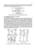
Figure 3.41. Schematic illustrations of a complete braille display unit
USB Controller
Microcontroller
DA Converter
&
Op-Amp
4 Channel output
Figure 3.42. Control and communication circuit board
The device is organized by cramming many small-scale actuators into a tiny space,
electrical wiring might be one of the key problems to be resolved. Identifying
constructional and functional analogies of the braille device to a computer input
keyboard, a control scheme, so-called dynamic scanning actuation(DSA), can be
88 H.R. Choi et al.
used here. This strategy enables easy control of nun braille cells with only 2n
electrical lines. The concept of the control is depicted in Figure 3.43. One of the
lines named a data line delivers high-voltage driving electric power to each cell
and the other line called a scan line functions as a ground. Therefore, each actuator
cell can be driven using n lines of the data line and n lines of the scan line with
alternating ‘On-Off’ patterns on both lines.
D
a
t
a
l
i
n
e
Scan line
D0
D1
D2
S0
S1
S2
Vertical scan
Horizontal scan
Actuator array
On
On On
On
Figure 3.43. Concept of dynamic scanning actuation
For example, refer to Figure 3.43, although the data lines D0, D1, D2 get
‘High’/‘On’ signal during three clocks, only one actuator located in the upper left
corner operates because only one scan line S0 maintains ‘High’/‘On’ during the
time. In essence, an actuator cell moves only if those two lines are synchronized
with a ‘High’/‘On’ signal. The scan frequency is L
u M when the number of
actuators in a row is M and the desired driving frequency is L.
Because a dielectric elastomer actuator normally operates with high electrical
voltage of about 1~2kV, introduction of the proposed control scheme DSA
provides significant benefits by reducing the number of required high-voltage
sources. For example, a single braille unit composed of six tactile cells can be
actuated with only a single voltage source, and the number of cells can be easily
expanded. In Figure 3.44, HVSC (high-voltage switching circuit) high-voltage reed
switches and photocouplers are shown. For faster actuator operation, the method
shown in Figure 3.30 has been implemented in the circuit.
C
o
n
t
r
o
l
i
n
p
u
t
High voltage reed switch
O
u
t
p
u
t
Figure 3.44. High-voltage switching circuit
Robotic Applications of Artificial Muscle Actuators 89
3.4 Conclusions
Research and development of the dielectric elastomer actuator have produced
significant progress for decades. A remarkable amount of work has focused on
delivering the feasibility of the industrial application of the material. However, few
commercial products equipped with polymer actuators have been introduced in the
market, probably because most of the research has been dedicated either to
discovering new actuation properties of the polymeric material or comparative
study of the operating range of a particular traditional actuator and its polymeric
substitute.
One of the implications of the term “actuator” might be a “controllable” motion
generator. If a material produces just some motions, it can not be referred as an
actuator unless its motions are controlled. The actuator designs introduced in this
chapter have been developed under a common philosophy that actuator motions
should be controllable with a reasonable amount of control actions. This clearly
differs from many previous developments. The physics of the polymeric material
actuation and its construction as an actuator is quite straightforward if a proper
application is well sought in advance. In other words, if a good application where
the polymer actuators can be used is established and the actuator functionality is
well defined, application of the current dielectric elastomer actuator technology to
industrial products could be accomplished before long. Future research activity
may focus on development of a new energy effective material that has higher
permittivity and creation of new application fields such as biomimetic robotics and
tactile or braille displays.
3.5 References
[1] Y. Osaka and D. E. DeRossi (1999) Polymer Sensors and Actuators, Springer.
[2] Y. Bar-Cohen (2002) Electroactive Polymers [EAP] Actuators as Artificial Muscles,
SPIE press.
[3] G. Kofod (2001) Dielectric Elastomer Actuators, Doctoral Dissertation, The
Technical University of Denmark.
[4] R. Perline, R. Kornbluh, et al. (2000), High-Speed Electrically Actuated Elastomer
with Strain Greater than 100 %, Science, Vol. 287, pp. 836-839.
[5] R. Perline, R. Kornbluh, and J. Joseph (1988), Electrostriction of Polymer Dielectrics
with Compliant Electrodes as a Means of Actuation, Sensors and Actuators, Vol. 64,
pp. 77-85.
[6] H. Choi, K. Jung, et al. (2005), Effect of Prestrain on Behavior of Dielectric
Elastomer Actuator, Proc. of 12th SPIE Conference, San Diego, CA.
[7] H. R. Choi, S. M. Ryew, K. M. Jung, H. M. Kim, J. W. Jeon, J. D. Nam, R. Maeda
and K. Tanie (2002), Soft Actuator for Robot Applications Based on Dielectric
Elastomer : Quasi-static Analysis,” Proc. IEEE Int. Conf. on Robotics and
Automation, pp. 3212-3217.
[8] H. R. Choi, S. M. Ryew, K. M. Jung, H. M. Kim, J. W. Jeon, J. D. Nam, R. Maeda
and K. Tanie (2002), Soft Actuator for Robot Applications Based on Dielectric
Elastomer : Dynamic Analysis and Applications, Proc. IEEE Int. Conf. on Robotics
and Automation, pp. 3218-3223.
90 H.R. Choi et al.
[9] H. R. Choi, K. Jung, S. Ryew, Jae-Do Nam, J. Jeon, J. C. Koo, and K. Tanie (2005),
Biomimetic Soft Actuator: Design, Modeling, Control, and Applications,
IEEE/ASME Transactions on Mechatronics, Vol.10, No.5. pp.581-586.
[10] S. Guo, T. Fukuda, and K. Asaka (2003), A New Type of Fish-Like Underwater
Microrobot, IEEE/ASME Trans. on Mechatronics, 8(1):136-141.
[11] M. Binnard and M. R. Cutkosky (2000), A Design by Composition Approach for
Layered Manufacturing, ASME Transactions, Journal of Mechanical Design, Vol.
122, No. 1, pp. 91-101.
[12] N. Asamura, T. Shinohara, Y. Tojo, N. Koshida, and H. Shinoda (2001), Necessary
Spatial Resolution for Realistic Tactile Feeling Display, Proc. Int. Conf. on Robotics
and Automation, pp.1851-1856.
[13] D. G. Caldwell, N. Tsagarakis, and C. Giesler (1999), An Integrated Tactile/Shear
Feedback Array for Stimulation of Finger Mechanoreceptor, Proc. IEEE Int. Conf. on
Robotics and Automation, pp.287-292.
4
Ferroelectric Polymers for Electromechanical
Functionality
J. Su
Advanced Materials and Processing Branch
Langley Research Center
National Aeronautics and Space Administration (NASA)
Hampton, Virginia 23681, U.S.A.
4.1 Introduction
Piezoelectric and ferroelectric polymers have been recognized as a new class of
electroactive materials since the significant piezoelectricity in polyvinylidene
fluoride (PVDF or PVF
2
) was discovered in 1969 by Kawai [1]. Since then, a
variety of new piezoelectric polymers have been developed including copolymers
of vinylidene fluoride and trifluoroethylene, p(VF
2
-TrFE), odd-numbered nylons,
composite polymers, etc. [2–8]. These materials offer options of material selection
for sensor and actuator technologies that need lightweight electroactive materials.
In this chapter, the origins of piezoelectricity and the properties of several kinds of
piezoelectric and ferroelectric polymeric materials are introduced for reference.
4.2 Dipole Moment and Polarization
4.2.1 Dipole and Dipole Orientation
An electric dipole can be defined as an entity in which a positive charge, q, is
separated by a relatively short distance, d, from an equal negative charge [9]. The
electric dipole moment,
P
, is a vector quantity and is defined as
P {
qd (4.1)
By convention, its direction points from the negatively charged end toward the
positively charged end. Traditionally, the Debye has been used as the unit of
measure of the dipole moment. In international units,
1 D = 3.338 u 10
-30
C-m (4.2)
92 J. Su
A dipole moment is defined as a permanent dipole moment if it exists in the
absence of an external electric field, while an induced dipole is the dipole formed
by an applied electric field. Besides these, "defect dipole moments" can be
introduced, which are associated with some structural heterogeneity, such as a
missing lattice site, crystallite interface, crystallite-amorphous interface in solids,
or an interface between two media [10]. At structural defects, the bonding energy
is decreased and the radius of the defects is, correspondingly, increased. In the
presence of an external electric field, a dipole may be formed at structural defects.
This can be referred to as a defect dipole. Since the bonding energy is dependent
on the dielectric constant of a medium, any heterogeneity in the dielectric constant
should result in a corresponding change in the formation of dipoles in the presence
of an external field. This change is known as the Maxwell-Wagner effect. If the
sample contains regions of different dielectric constants in an external electric
field, an interfacial dipole polarization builds up [11]. The electric dipoles
mentioned above are schematically illustrated in Figure 4.1.
Figure 4.1. Schematical illustrations of the formation of a dipole. (a) a typical dipole, (b) a
defect dipole, and (c) interfacial dipoles when an interface is formed by two consituents that
have different dielectric constants (H
1
H
2
).
Figure 4.2. The torque acting on a dipole under an electric field
When an electric field is applied to a permanent dipole, the positive charge at one
end of the dipole experiences a force in the direction of the applied field and the
negative charge experiences an equal force in the opposite direction.
Consequently, the net force on the dipole is zero; therefore, the translational
movement will be zero. However, the charges are separated by a fixed
d
-q
-
+ + + +
_ _ _ _
H
H
(a) (b) (c)
+q
-q
+q
o
T
F
+
P
F
-
F
+
sin
T
F
-
sin
T
E