Electroactive Polymers for Robotic Applications - Kim & Tadokoro (Eds.) Part 9 ppt
Bạn đang xem bản rút gọn của tài liệu. Xem và tải ngay bản đầy đủ của tài liệu tại đây (456.05 KB, 20 trang )
6
Ionic Polymer-Metal Composite as a New Actuator and
Transducer Material
K. J. Kim
Active Materials and Processing Laboratory, Mechanical Engineering Department (MS 312),
University of Nevada, Reno, Nevada 89557, U.S.A.
6.1 Introduction
Ionic polymer-metal composites (IPMCs) are a unique polymer transducer that
when subjected to an imposed bending stress exhibits a measurable charge across
the chemically and/or physically placed effective electrodes of the electroactive
polymer. IPMCs are also known as bending actuators capable of large bending
motion when subjected to a low applied electric field (~10 kV/m) across the
metalized or conductive surface (Figure 6.1). The voltage found across the IPMC
under an imposed bending stress is one to two orders of magnitude smaller than the
voltage required to replicate the bending motion input into the system. This leads
to the observation that the material is quite attractive by showing inclination for
possible transduction as well as actuation [1–25]. In 1993, an IPMC was first
reported as an active polymeric material by Oguro and his co-workers [21]. Since
then, much attention has been given to IPMCs with the hope that they can be used
as a soft actuator and sensor/transducer material for new opportunities in future
engineering. IPMCs have been considered promising actuator materials, in
particular for biorobotic applications.
Figure 6.1. Actuation of a typical IPMC (from [8])
Part of what makes an IPMC so unique are its inherent transductive/sensing
properties in addition to its actuation capabilities. Similar to piezo materials,
IPMCs can show displacements under an applied electric field and can also
154 K. J. Kim
engender a current from an imposed bending moment that is applied to the material.
The voltage can be as high as in the 10’s of millivolts range for larger imposed
bending displacements. This makes IPMCs possibly effective for large motion
sensor or damper applications if their behavior can be properly controlled.
6.2 How IPMC Works
In 2000, De Gennes et al. [18] presented a set of coupled equations based on linear
irreversible thermodynamics to describe the behavior of a typical IPMC. The
model is a compact description of the transduction and actuation principles
inherent in the IPMC by defining it in the linear regime and in static conditions.
They introduce the linear irreversible thermodynamic relationship for charge
transport (with a current density J normal to the membrane) and solvent transport
(with a flux Q) to describe this electromechanical coupling of ionic gels (i.e.
IPMCs, see Figure 6.2 [18]). The standard Onsager relations for the system have
the form,
pLEJ
12
V
(6.1)
pKELQ
21
(6.2)
Equations (6.1) and (6.2) couple the electric field, E, as well as the mechanical
pressure gradient, p, the driving forces for the phenomenon involved. These
equations can be elaborated upon to explain the direct effect (actuation) as well as
the inverse effect (sensing or transduction) of IPMCs. Note that these Onsager
relations developed by De Gennes et al. are for a static model. Note also that ı,
L
12
(=L
21
), and K are electric conductance, cross-coefficient, and permeability,
respectively.
-
-
-
-
-
-
-
-
+
+
+
++
+
+
+
E
P
<
P
>
h
WATER
ț
E
İ
+
İ
c
İ
-
-
-
-
-
-
-
-
-
+
+
+
++
+
+
+
E
P
<
P
>
h
WATER
ț
E
İ
+
İ
c
İ
-
Figure 6.2. Principle of the bending motion. K
E
, h, E, and P are the curvature, specimen
thickness, electric field, and ionic pressure of the system.
Ionic Polymer-Metal Composites as a New Actuator and Transducer Material 155
IPMCs as transducers have been modeled and developed for actuation, sensing.
and control applications by several investigators. Their work can be found
elsewhere [19–25].
6.3 IPMC Manufacturing Techniques
6.3.1 Metal Reduction Technique
The current state-of-the-art IPMC manufacturing technique [6] incorporates two
distinct preparation processes: initial compositing process and surface electroding
process. Due to different preparation processes, the morphologies of precipitated
platinum are significantly different. The initial compositing process requires an
appropriate platinum salt such as Pt(NH
3
)
4
HCl for chemical reduction processes.
The principle of the compositing process is to metalize the inner surface of the
material (usually, Pt nano–particles, in a membrane shape) by a chemical-reduction
means such as LiBH
4
or NaBH
4
. The ion-exchange polymer is soaked in a salt
solution to allow platinum-containing cations to diffuse through via the ion-
exchange process. Later, a proper reducing agent such as LiBH
4
or NaBH
4
is
introduced to platinize the materials by molecular plating. It has been
experimentally observed that the platinum particulate layer is buried a few microns
deep (typically 1–10 Pm) within the IPMC surface and is highly dispersed. A TEM
image near the boundary region of an IPMC strip on the penetrating edge of the
IPMC shows a functional particle density gradient where the higher particle
density is toward the surface electrode. Figure 6.3 describes Ni-doped IPMC
manufacturing developed at the Active Materials and Processing Laboratory of the
University of Nevada, Reno.
6.3.2 Physical Loading Technique
Although the traditional metal reduction processes described above are known to
be effective in manufacturing IPMCs, one may realize that one drawback of using
these processes is their relatively high cost due to the use of noble metals
(platinum, gold, palladium, etc.) and associated complex chemical processes. For
IPMCs to be successfully adopted as industrial actuators or sensors, one should be
able to reduce their manufacturing cost significantly. One way to do so is to
simplify the compositing and electroding processes.
The principal idea of processing this new IPMCs is first to physically load a
conductive primary powder into the polymer network forming a dispersed layer
which can function as a major conductive medium near boundaries and,
subsequently, to further secure such a primary particulate medium within the
polymer network with smaller particles (Pd or Pt in this case) via a chemical
plating process so that both primary and smaller secondary particles can be secured
within the polymer network. Furthermore, an electroplating process can be applied
to integrate the entire conductive phase intact, serving as an effective electrode. For
more details, readers are referred to recent work done by Shahinpoor and Kim [15].
156 K. J. Kim
This physical loading technique has been elaborated by Leo and his co-workers
[25]. They used a high surface area-to-volume ratio of metal particulates to
achieve high capacitance at low frequencies.
Figure 6.3. Experimental procedure for Ni-doped IPMCs using the ion-exchange and
precipitation method
6.4 Engineering Properties of Interest
In this section, important engineering properterties of typical IPMCs are presented.
6.4.1 Mechanical Properties
Figure 6.4 shows the results of dynamic material analysis (DMA) tests for a
pristine Nafion
TM
film and a Ni-doped IPMC in tensile. The experiment was
performed in air. In the tensile mode, Ni-doped IPMCs have higher storage
modulus (E’) with regard to stiffness than pristine Nafion
TM
film.
Rinsing in DI water
Stirring a 1 M nickel (II) sulfate hexahydrate (NiSO
4
•6H
2
O)
solution for 24 h
Immersing in a sodium borohydride solution for 3 h
XRD SEM
VSM
Pre treatment of Nafion 1110
Rinsing in DI water
Rinsing in DI water
Conditioning
C
y
clic Voltammo
g
rams
DMA
Ionic Polymer-Metal Composites as a New Actuator and Transducer Material 157
0 20406080100
0
200
400
600
800
1000
E', Storage Modulus (MPa)
Frequency (Hz)
0 20406080100
0
5
10
15
20
25
30
E", Loss modulus (MPa)
Frequency (Hz)
(a) (b)
Figure 6.4. DMA results of the pristine Nafion film (Ŷ) and metal-doped IPMCs (Ɣ and Ÿ).
The results are storage modulus (a) and loss modulus (b) with a frequency range from 0.01
to 100 Hz in the tensile mode
6.4.2. Electrical and Electrochemical Properties
6.4.2.1 General Electrical Properties
To assess the electrical properties of an IPMC, the standard AC impedance method
that can reveal the equivalent electric circuit has been adopted. A typical measured
impedance plot, provided in Figure 6.5, shows the frequency dependency of the
impedance of the IPMC. It is interesting to note that the IPMC is nearly resistive in
the high–frequency range and fairly capacitive in the low–frequency range.
f (Hz)
10
0
10
1
10
2
10
3
10
1
10
2
10
3
Z (
:
)
Figure 6.5. The measured AC impedance spectra (magnitude) of an IPMC sample [6]
Based upon the above findings, a simplified equivalent electric circuit of the
typical IPMC can be considered, such as the one shown in Figure 6.6. In this
approach, each single unit-circuit (i) is assumed to be connected in a series of
arbitrary surface-resistance (R
ss
) in the surface. This approach is based upon the
experimental observation of the considerable surface-electrode resistance. We
assume that there are four components to each single unit-circuit: the surface-
electrode resistance (R
s
), the polymer resistance (R
p
), the capacitance related to the
ionic polymer and the double layer at the surface-electrode/electrolyte interface
(C
d
), and an impedance (Z
w
) due to charge transfer resistance near the surface
158 K. J. Kim
electrode. For the typical IPMC, the importance of R
ss
relative to R
s
may be
interpreted from
1//
sss
!!|6 tLRR , where notations L and t are the length and
thickness of the electrode, respectively.
single un it -ci rcuit
R
s
R
p
Z
w
C
d
R
s
R
s
R
p
Z
w
C
d
R
s
R
s
R
p
Z
w
C
d
R
s
(i) (i+1)(i-1)
R
ss
R
ss
R
ss
R
ss
Figure 6.6. A possible equivalent electric circuit of a typical IPMC membrane [6]
6.4.2.2 Electrochemical Properties
Figure 6.7 shows cyclic voltammograms of an IPMC with platinum electrodes.
Potentiostat/galvanostat (PGZ40, Voltalab) was used for the cyclic voltammetry as
well as AC impedance. By examining the voltammogram of the IPMC, it is clear to
see the polycrystalline characteristics of the platinum that has been significantly
altered by the presence of the base polymeric material within the testing specimen
showing a unique behavior. This exhibits the importance of the surface properties
of the electrodes of an IPMC. The electrochemical behavior at the surface
electrodes is yet to be determined and is currently under investigation.
0 20 40 60 80 100 120 140 160 180
-5
0
5
10
15
20
25
30
35
40
-Z
i
:.cm
2
)
Z
r
(:.cm
2
)
-0.4 -0.2 0.0 0.2 0.4 0.6 0.8 1.0 1.2 1.4
-15
-10
-5
0
5
10
Current density (mA / cm
2
)
Potential(V vs. SCE)
(a) (b)
Figure 6.7. Electrochemical impedance behavior (a) and cyclic voltammograms (b) with a
scan rate of 50 mV/s in 0.5M sulfuric acid of an IPMC [5]
6.4.2.3 Measurement of the Force-displacement Relationship
The electromechanical properties considered are determined by the force–
displacement relationship of an IPMC actuator. The method used to measure these
properties is graphically depicted in Figure 6.8. An IPMC actuator is cantilevered
at one end, and the other end is constrained, as shown in Figure 6.8a. The reaction
force (or actuation force) at the right end of the actuator is generated by an
Ionic Polymer-Metal Composites as a New Actuator and Transducer Material 159
electrical field. We measure the reaction force with a small force transducer. After
the right-end constraint is moved up with amount of the displacement
s
, the same
test is conducted. In this way, the actuation force corresponding to the end
displacement
s can be measured, as illustrated in Figure 6.8b. Finally, without the
constraint, the free end displacement can be determined. Following this procedure,
the force-displacement relationship was obtained as shown in Figure 6.9. Figure
6.9 shows the measured force-displacement relationship for an IPMC actuator for
two- and three-volt inputs across the IPMC. Regions A and B in Figure 6.9 include
the maximum actuation forces and the maximum displacements, respectively. The
specimen tested was a Nafion
TM
-based IPMC in Li
+
form and plated with platinum.
The length of the IPMC actuator was 20 mm with a width of 5 mm and a thickness
of 0.3 mm.
IPMC actuator
Force transducer
IPMC actuator
s
(a) (b)
Figure 6.8. Test setup for the force-displacement relationship ([4])
0
0.5
1
1.5
2
00.511.522.533.54
3V(Measured)
2V(Measured)
F(g)
s(mm)
B
A
Figure 6.9. Force-displacement relationship of an IPMC actuator ([4])
Thus, the force
F
for
0s
(region A in Figure 6.9) is the reaction force for the
case shown in Figure 6.8a, and the measured displacement
s
when 0F (region
B in Figure 6.9) stands for the tip displacement without the right-end constraint.
160 K. J. Kim
6.5 Robotic Flapping Wings
Pneumatic and motor-driven actuators have been widely adopted and used in
aerospace applications as well as in other industrial robot systems. However, these
actuators are not feasible for use in small or microscale flying and locomotive
vehicles due to their large payload and system complexity. Furthermore, they are
not suitable for mimicking the flapping motion of bird or insect wings. Using
microrobots to create flapping flight is attractive due to their maneuverability that
could not be obtained by conventional, fixed or rotary wing aircraft. An
electroactive polymer, IPMC is a good candidate for the flapping motor because it
is lightweight and can create a large deformation under low electric voltage input.
Bird/insect wings can generate lift and thrust at the same time during flapping
motion because the wing can flap and twist during the flapping motion [26]. To
mimic the motion, the artificial flapping mechanism should also be able to create
flap and twist simultaneously. Also, the width of a bird wing tip is pointed
compared with the remaining parts of the wing. This reduces drag during the up-
/down-strokes of the wing and also strengthens the tip of the vortex. Thus, the
actuation mechanism and shape are both important for successfully mimicking a
bird wing. The IPMC can generate this particular motion if it has a specially
designed plan form.
Since the flapping wing must create a twisting motion as well as a bending up
and down motion for thrust generation, the IPMC actuators have nonsymmetric-
shapes, as shown in the two wings in Figure 6.10. The wing shapes and dimensions
of the wings are also shown in Figure 6.10. Note that the areas of the IPMC
actuators in the two wings are kept the same for fair comparison in the actuation
displacement analysis. The wing itself is made of a thin plastic film.
3cm
8 cm
3 cm
2 cm
1 cm
1cm
1.0cm
5cm
IPMC
1cm
1cm
1cm
slot
1.25 cm
4.5cm
1cm
45 degree
IPMC
3cm
1cm 1cm
0.5cm
slot
(a) Wing #1 (b) Wing #2
Figure 6.10. Flapping wing and patterns of IPMC actuators ([27])
The numerical deformation analysis has been conducted to determine the shape of
the IPMC actuator such that the designed wing can produce maximum bending and
twisting motion at the same time. Deformation of the wing has been estimated by
using the equivalent bimorph beam model and MSC/ NASTRAN with the thermal
analogy. For finite-element modeling, QUAD4 elements were used for both Wing
#1 and #2 as shown in Figure 6.11a and Figure 6.12a. Material properties and
thicknesses for the calculations are shown in Table 6.1.
Ionic Polymer-Metal Composites as a New Actuator and Transducer Material 161
Table 6.1. Material properties and thicknesses
Young’s
modulus (GPa)
Poisson’s
ratio
d
31
= d
32
(m/V)
t (mm)
IPMC 1.158* 0.487 1.750×10
-7
0.3
Plastic
film
0.1 0.3 N/A 0.1
Pt (~6%) heavy IPMC
(a) Finite-element model (b) Deformed shape
Figure 6.11. Flapping simulation for flapping wing #1 ([27])
(a) Finite-element model (b) Deformed shape
Figure 6.12. Flapping simulation for flapping wing #2 ([27])
The flap-up displacement and twisting angle at the tip under 3 V (i.e.,
3
E = 10
V/mm) are calculated as 4.42 cm and 3.4º, for Wing #1, and 4.68 cm and 9.1º, for
Wing #2. The deformed shapes are shown in Figure 6.11b and Figure 6.12b for
Wing #1 and #2, respectively. Wing #2 is the better design for the flapping wing in
terms of a twisting angle. Noted that our analysis is based on linear elasticity and
thus may not accurately predict the actuation displacement. However, the present
approach provides a simple but effective design tool to determine the shape of an
IPMC actuator for a specific purpose.
162 K. J. Kim
6.6 Summary and Acknowledgments
In this chapter, the fundamental properties and a brief summary of recent progress
in ionic polymeric-metal composites (IPMCs) as smart biomimetic sensors,
actuators, and artificial muscles were presented. In the following Chapters 7, 8, 9,
and 10, detailed robotics-related work on IPMCs is presented by many
investigators from RIKEN, AIST, the Tokyo Institute of Technology, Tohoku
University, the University of Nevada, Las Vegas, and the University of Nevada,
Reno.
Also, I would like to extend my special thanks to many earlier investigators
including Drs. K. Oguro (Osaka National Research Institute), M. Shahinpoor
(University of New Mexico), K. Asaka (
Research Institute for Cell Engineering,
AIST)
, Y. Bar-Cohen (NASA Jet Propulsion Laboratory), S. Nemat-Nasser
(University of California, San Diego), and D. Leo (Virginia Tech). Their dedicated
work toward IPMCs is invaluable. The research work regarding IPMCs performed
by Drs. H.C. Park, S.K. Lee, I.S. Park and, Mr. D. Kim is also appreciated.
6.7 References
[1] K.J. Kim, W. Yim, J.W. Paquette, and D. Kim, Ionic Polymer-Metal Composites for
Underwater Operation, Journal of Intelligent Materials Systems and Structures
(JIMSS), (2006, in print).
[2] D. Kim and K.J. Kim, Experimental Investigation on Electrochemical Properties of
Ionic Polymer-Metal Composite, Journal of Intelligent Materials Systems and
Structures (JIMSS), (2006, in print).
[3] D.Y. Lee, M H. Lee, K.J. Kim, S. Heo, B Y. Kim, and S J. Lee, Effect of
Multiwalled Carbon Nanotube (M-CNT) Loading on M-CNT Distribution Behavior
and the Related Electromechancial Properties of the M-CNT Dispersed Ionomeric
Nanocomposites, Surface Coatings and Technology, Vol. 200(5-6), pp. 1916-192
(2005).
[4] S-K. Lee, H.C. Park, and K.J. Kim, Equivalent Modeling for Ionic Polymer-Metal
Composite Actuators Based on Beam Theories, Smart Materials and Structures, Vol.
14, pp. 1363-1368 (2005).
[5] J.W. Paquette, K.J. Kim, D. Kim, and W. Yim, The Behavior of Ionic Polymer-Metal
Composites in a Multi-Layer Configuration, Smart Materials and Structures, Vol. 14,
881-888 (2005).
[6] M. Shahinpoor and K.J. Kim, Ionic Polymer-Metal Composite-IV: Industrial and
Mechanical Applications, Smart Materials and Structures, Vol. 14, 197-214 (2005);
M. Shahinpoor and K.J. Kim, Ionic Polymer-Metal Composites: III. Modeling and
Simulation as Biomimetic Sensors, Actuators, Transducers, and Artificial Muscles,
Smart Materials and Structures, Vol. 13, pp. 1362-1388 (2004); K.J. Kim and M.
Shahinpoor, Ionic Polymer-Metal Composites - II. Manufacturing Techniques, Smart
Materials and Structures, Vol. 12, No. 1, pp. 65-79 (2003); M. Shahinpoor and K.J.
Kim, Ionic Polymer-Metal Composites – I. Fundamentals, Smart Materials and
Structures, Vol. 10, pp. 819-833 (2001).
[7] J D. Nam, J.H. Lee, J.H. Lee, H. Choe, K.J. Kim, and Y.S. Tak, Water Uptake and
Migration Effects of Electroactive IPMC(Ion-Exchange Polymer-Metal Composite)
Actuator, Sensors and Actuators A: Physical, Vol. 118, pp. 98-106 (2005).
Ionic Polymer-Metal Composites as a New Actuator and Transducer Material 163
[8] J.W. Paquette, K.J. Kim, and D. Kim, Low Temperature Characteristics of Ionic
Polymer-Metal Composite Actuators, Sensors and Actuators A: Physical, Vol. 118,
pp. 135-143 (2005).
[9] J. Paquette and K.J. Kim, Ionomeric Electro-Active Polymer Artificial Muscle for
Naval Applications, IEEE Journal of Oceanic Engineering (JOE), Vol. 29, No. 3, pp.
729-737 (2004).
[10] J. Paquette, K.J. Kim, J D. Nam, and Y. S. Tak, An Equivalent Circuit Model for
Ionic Polymer-Metal Composites and Their Performance Improvement by a Clay-
Based Polymer Nano-Composite Technique, Journal of Intelligent Materials Systems
and Structures (JIMSS), Vol. 14, pp. 633-642 (2003).
[11] J D. Nam, H.R. Choi, Y.S. Tak, and K.J. Kim, Novel Electroactive, Silicate
Nanocomposites Prepared to Be Used as Actuators and Artificial Muscles, Sensors
and Actuators: A. Physical, Vol. 105, pp. 83-90 (2003).
[12] M. Shahinpoor, K.J. Kim, and D. Leo, Ionic Polymer-Metal Composites as
Multifunctional Materials, Polymer Composites, Vol. 24, No. 1, pp. 24-33 (2003).
[13] M. Shahinpoor and K.J. Kim, Experimental Study of Ionic Polymer-Metal
Composites in Various Cation Forms: Actuation Behavior, Science and Engineering
of Composite Materials, Vol. 10, No. 6, pp. 423-436 (2002).
[14] M. Shahinpoor and K.J. Kim, Mass Transfer Induced Hydraulic Actuation in Ionic
Polymer-Metal Composites, Journal of Intelligent Materials Systems and Structures
(JIMSS), Vol. 13, No. 6, pp. 369-376 (2002).
[15] M. Shahinpoor and K.J. Kim, A Novel Physically-Loaded and Interlocked Electrode
Developed for Ionic Polymer-Metal Composites (IPMCs), Sensors and Actuator: A.
Physical, Vol. 96, No. 2/3, pp. 125-132 (2002).
[16] K.J. Kim and M. Shahinpoor, Development of Three Dimensional Ionic Polymer-
Metal Composites as Artificial Muscles, Polymer, Vol. 43(3), pp. 797-802 (2002).
[17] M. Shahinpoor and K.J. Kim, The Effect of Surface-Electrode Resistance on the
Performance of Ionic Polymer-Metal Composite (IPMC) Artificial Muscles, Smart
Materials and Structures, Vol. 9, No. 4, pp. 543-551 (2000).
[18] P.G. de Gennes, K. Okumura, M. Shahinpoor, and K.J. Kim, Mechanoelectric Effects
in Ionic Gels, Europhysics Letters, Vol. 50, No. 4, pp. 513-518 (2000).
[19] S. Nemat-Nasser, Micromechanics of Actuation of Ionic Polymer-Metal Composites,
Journal of Applied Physics, Vol. 92, No. 5, pp. 2899-2910 (2002).
[20] S. Nemat-Nasser and C.W. Thomas, Ionomeric Polymer-Metal Composites, in
Electroactive Polymer (EAP) Actuators as Artificial Muscles, Reality, Potential, and
Challenges, ed. Bar-Cohen, Y., SPIE Press, Washington, (2001).
[21] K. Oguro, K. Asaka, and H. Takenaka, Actuator Element, U.S. Patent #5,268,082,
(1993).
[22] S. Tadokoro, T. Takamori, T., and K. Oguro, Modeling IPMC for Design of Actuation
Mechanisms, in Electroactive Polymer (EAP) Actuators as Artificial Muscles,
Reality, Potential, and Challenges, ed. Bar-Cohen, Y., SPIE Press, Washington,
U.S.A., (2001).
[23] K. Asaka, K. Oguro, Y. Nishimura, M. Mizuhata, and H. Takenaka, Bending of
Polyelectrolyte Membrane-Platinum Composites by Electric Stimuli, I. Response
Characteristics to Various Waveforms, Polymer Journal, Vol. 27, No. 4, pp. 436-440
(1995).
[24] B.J. Akle, M.D. Bennet, and D. Leo, High Strain Ionomeric-Ionic Liquid
Electroactive Actuators Sensors and Actuators A (in press, 2006).
[25] M.D. Bennett and D.J. Leo, Ionic Liquids as Solvents for Ionic Polymer Transducers,
Sensors and Actuators A: Physical, Vol. 115. pp. 79–90 (2004).
[26] D.E. Alexander, Nature’s Flyers, Chapter 4. London, The Johns Hopkins University
Press (2003).
164 K. J. Kim
[27] H.C. Park, S. Lee, and K.J. Kim, Equivalent Modeling for Shape Design of IPMC
(Ionic Polymer-Metal Composite) as Flapping Actuator, Key Engineering Materials,
Vol. 297-300, pp. 616-621 (2005).
7
Biomimetic Soft Robots Using IPMC
Y. Nakabo
1
, T. Mukai
2
, K. Asaka
3
1
Bio-Mimetic Control Research Center, RIKEN,
2271-130 Anagahora, Shimoshidami, Moriyama, Nagoya 463-0003, Japan and
Intelligent Systems Institute, National Institute of AIST,
1-1-1 Umezono, Tsukuba, Ibaraki 305-8568, Japan
2
Bio-Mimetic Control Research Center, RIKEN
3
Research Institute for Cell Engineering, National Institute of AIST,
1-8-31 Midorigaoka, Ikeda, Osaka 563-8577, Japan and
Bio-Mimetic Control Research Center, RIKEN
7.1 Introduction
7.1.1 Ionic Polymer-Metal Composite (IPMC)
A bimorph-type soft polymer gel actuator, which we call an artificial muscle, is an
ionic polymer-metal composite (IPMC) consisting of a perfluorosulfonic acid
membrane with chemically plated gold or platinum as electrodes on both sides [18,
1]. It has some excellent characteristics for robotic applications compared with
other soft polymer actuators [2] as follows.
Driven with low voltage (<3 V).
Low power consumption.
Fast response (>10 Hz in water).
Mechanically and chemically durable and stable.
Soft and compliant.
Works in water (or in wet conditions).
Moreover, it has an advantage for miniaturization with its simple actuator
structure. With these characteristics, we expect to apply it to micromanipulations in
the bioengineering or medical fields. Our goal is to realize bioinspired soft robots,
for example, a snake-like swimming robot [15, 16, 17] or a multi-degree-of-
freedom (DOF) microrobot manipulator [13, 14].
The snake-like motion of a swimming robot sweeps a smaller area than a
simple bending motion. It is easy to miniaturize the actuator because of its simple
structure. In the future, we may be able to make robots that can swim in thin tubes
or in blood vessels, or various kinds of micromanipulators in the biomedical field.
166 Y. Nakabo, T. Mukai, and K. Asaka
7.1.2 Multi-DOF Motion of IPMC
To realize a snake-like or a multi-DOF bending motion, we laser cut special
electrode patterns on the surface of the actuator to control each segment
individually.We have developed a variety of motions from this patterned actuator,
including a snake-like motion. A kinematic modeling of the manipulator simply
describes various multi-DOF motions of the artificial muscle. This model is
applied to visual feedback control of the manipulator system using a Jacobian
control method. For the feedback control, we have developed a visual sensing
system using a 1 ms high-speed vision system which has a fast enough response to
capture the fast actuator motion.
We have also measured the propulsion speed generated by the snake-like
motion. By changing voltages and phases to each segment, we can control the
direction of the propulsion. Finally, we have made the robot swim freely forward
and backward by finding the optimal voltage, phase, and frequency. In this report,
we show some results from simulations of the proposed manipulator control
method and experimental results from visual sensing of the bending motion and
snake-like swimming of the actuator.
7.2 Multi-DOF Microrobot Manipulator
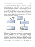
7.2.1 Concept of Multi-DOF Microrobot Manipulator
Micromanipulations in bioengineering or in the medical field can be one of the
applications of the artificial muscle. Our goal is to realize a multi-DOF microrobot
manipulator that is automatically controlled by visual feedback, as shown in Figure
7.1.
In previous research studies on manipulators using an IPMC, Tadokoro et al.
have fabricated a multi-DOF micromanipulator using a “3D-EFD” element [19]
that consists of two arch-shaped IPMC components placed crosswise and works
with a mechanism similar to that of parallel-link manipulators. Guo et al. have
developed a multi-DOF microcatheter with active guide wires [6]. Using this
catheter at a diverging point of a vessel, the direction of the catheter can be
selected by the bending motion of an IPMC. However, up to this point, the
kinematic modeling of multi-DOF bending motions or automatic visual feedback
control have not yet been attempted. Automatic control will be required for
applications of micromanipulators.
On the other hand, Mallavarapu et al. have implemented feedback control for
dynamic bending motions in IPMC membranes [10]. They measured the bending
motions of IPMC using a laser vibrometer to identify the dynamic models of
bending responses to electrical stimuli and controlled them by sensor feedback.
However, a laser vibrometer can only measure a distance from the sensor to a
certain point of an IPMC; it cannot measure various shape changes in multi-DOF
motion. For this, we need a better vision sensor.
In this research, we propose to use visual information for automatic feedback
control of the IPMC. Our 1 ms vision system [12] enables high-speed and contact-
Biomimetic Soft Robots Using IPMC 167
free measurement of fast shape changes in an IPMC. Also, we propose a new type
of multi-DOF manipulator that is compactly designed using a patterned artificial
muscle. The patterning of electrodes on an IPMC enables the multi-DOF bending
motions of a manipulator with a simple structure.
Figure 7.1. Application of multi-DOF micromanipulator with artificial muscle and visual
feedback control
In the next section, we will describe details of our manipulator and how the
patterning is carried out on the electrodes. The kinematic modeling for visual
control is described in Section 7.4. The visual sensing system and proposal of
feedback control are shown in Section 7.5. In Section 7.6, the experimental results
of visual sensing are presented.
7.3 Patterned Artificial Muscle
7.3.1 Patterning with a Laser Beam
One way to realize this multi-DOF motion is to connect some of them using joints.
The process of connecting them together is, however, complex, and it is difficult to
make the joints flexible. So we propose another method to realize multiple degrees
of freedom. In this method, we make special electrode patterns separated
electrically by laser-cutting the gold-plated surface of the IPMC to control each
segment individually. This method makes the IPMC bend as required without
losing flexibility, and it is suitable for miniaturization because the process is
simple.
The IPMC used in this study is a Nafion 117 membrane (by DuPont) five times
chemically plated with gold. The thickness of the IPMC is 200 ȝm. After the
plating, we cut a pattern on both sides of the membrane using a laser beam. By
laser patterning, the thin gold layer is removed, and insulation between segments of
the electrodes is achieved. By optimizing the conditions of the bursts of the laser
Hand-arm
manipulator with
artificial muscle
Visual feedback control
Target object
Kinematic model,
Actuator controller
High-speed
vision system
Visual sensing
168 Y. Nakabo, T. Mukai, and K. Asaka
beam, sufficient insulation was achieved at the minimum groove size of 50 ȝm
wide and approximately 20 ȝm deep.
Photomicrographs of the laser-cut pattern are shown in Figure 7.2. The left
photograph shows a cross section of the membrane with a groove and a gold layer.
The right one shows a closeup of the segmented electrodes seen from above the
membrane. In both photographs, plated gold remained in the bright areas and was
removed in dark areas. The photographs have different magnifications, but the
minimum width of insulation grooves is the same (50 ȝm). From the photographs,
the sharp lines cut by the laser can be seen.
Figure 7.2. Results of laser beam patterning. (a) cross section of membrane with groove and
plated gold layer, (b) patterned lines viewed from above
7.3.2 Patterning for a Multi-DOF Manipulator
Using the above laser cutting method, we have formed the electrode pattern shown
in Figure 7.3. The pattern on the opposite side of the membrane has small
differences only at the interconnections of electrodes.
Figure 7.3. Pattern of electrodes on IPMC
The pattern on the membrane consists of three areas, a connector area, an arm area,
and a hand area. The connector area is for providing electricity and mounting the
manipulator to a stable base through an electric connector. The arm area is
composed of three wide insulated segments for multi-DOF arm bending and many
thin lines for electrical interconnections. Finally, the hand area is composed of
three segments that are mechanically split so that it can grab a target object, as
33
0.3
3
0.3
16
65
2.5
161610
0.3
0.3
5.5
7
0.3
2
2
7
Connector area
Arm area
Hand area
(mm)
50
P
m
Gold laye
r
Polymer
gel layer
50
P
m
(a) (b)
Biomimetic Soft Robots Using IPMC 169
shown in Figure 7.4. A photograph of the patterned IPMC is shown in Figure 7.5.
Note that three beads are attached to the joints of the arm segments, which are used
for visual sensing, as explained later.
Figure 7.4. Hand with its open and grabbing position
Figure 7.5. Patterned IPMC manipulator
7.4 Kinematic Modeling
7.4.1 Modeling of One-Link Kinematics
Next we propose the kinematic model of an IPMC. Our approach is similar to the
modeling of conventional serial-link multi-DOF robot manipulators, but has a
marked difference in that instead of joint rotation, the link itself bends on an IPMC.
We treat each segment of an electrode as a link of a manipulator that can be bent
independently. Figure 7.6 shows the kinematic model of a one-link bending motion.
We assume that a link bends with a constant curvature. Although this assumption is
not true for very large bending angles in real IPMC membranes, it is the first step
in the approximation in kinematic modeling, and for small values of curvature, this
is a good approximation.
170 Y. Nakabo, T. Mukai, and K. Asaka
Either from the kinematic model or from real IPMC bending motion, it is
important to note that the position and direction of an end point of the link is
restricted to one constant trajectory, that is, one link can make only one DOF
motion.
7.4.2 Modeling of Multi-Link Kinematics
To realize the multi-DOF motion of a manipulator, we can connect several links in
series in the same way as in conventional serial-link manipulators. In this study, as
a first step in our research, we restrict the motion of the manipulator to a two-
dimensional space, in which two DOF for position and one DOF for the tangential
direction of the end point are controlled. We can control all three DOF
independently by controlling the three links of an IPMC.
We now define coordinate systems
^`
3,2,1,0, iȈ
i
one at the origin, one at
each joint of the multi-link system, and one at the end point of an arm, as shown in
Figures 7.6 and 7.7. A homogeneous transfer matrix
1i
i
A
from
1i
Ȉ to
i
Ȉ is
written as
¸
¸
¸
¸
¸
¸
¸
¹
·
¨
¨
¨
¨
¨
¨
¨
©
§
100
sincossin
cos1sincos
1 i
i
i
iiii
i
i
i
iiii
i
i
l
l
A
T
T
DTDT
T
T
DTDT
(7.1)
Figure 7.6. One-link kinematic modeling (note that usually 0
i
D
, as in this study)
where the certain length of a link is
i
l , the curvature is
iii
lr
T
, and if the link
has a certain bending angle at the joint, this angle is referred as
i
D
. We consider
that
i
l and
i
D
are known (also 0
i
D
in this study) .
l
i
r
i
x
y
x
y
i
(=
l
i
/
r
i
)
l
i
i
+1
6
i
i
+1
6
x
y
i
A
i
+1
i
6
Biomimetic Soft Robots Using IPMC 171
Figure 7.7. Multi-link coordinate system (note that joints are usually not bent, as in this
study)
A transfer matrix from the base to the end point is calculated by multiplying each
matrix of the link from the first to the last using
3
2
2
1
1
0
3
0
AAAT
(7.2)
which is shown in Figure 7.7. From this equation, we can obtain the position vector
e
P
0
and rotation angle
e
Ĭ
0
of the end point in the base coordinate system
0
Ȉ as
follows (where
t
eeyex
t
ee
PPPĬP
T
,,,
00
e
P ) :
210210
0
0
0
00
1
1
010
1
1
1010
2
2
10210
2
2
0
0
0
00
1
1
010
1
1
1010
2
2
10210
2
2
sinsinsin
sinsin
1coscoscos
coscos
DDDTTT
T
T
DT
T
DTT
T
DDTT
T
DDTTT
T
T
T
DT
T
DTT
T
DDTT
T
DDTTT
T
T
e
ey
ex
P
l
ll
ll
P
l
ll
ll
P
(7.3)
7.4.3 Position and Orientation Control Based on a Kinematic Model
To control the position and orientation of the hand of the manipulator, we have to
solve an inverse kinematic problem. More specifically, we have to solve
șPP
ee
ˆ
by
t
210
,,
TTT
ș from Eq. (7.3), where
e
P
ˆ
denotes both the
x
y
0
6
2
6
1
6
3
6
3
0
T
172 Y. Nakabo, T. Mukai, and K. Asaka
objective position and orientation. However, it is quite difficult to solve Eq. (7.3);
thus we use Jacobian methods for controlling and define control variables to
converge to objective values. The Jacobian of
e
P with ș is defined as
>@
210
JJJJ (7.4)
^`
2,1,0,
w
w
i
i
i
e
PJ
T
Using the Jacobian, the following control, which is an inverse Jacobian method,
will induce the control variable to converge to an objective value
e
P
ˆ
exponentially.
ee
PPJș
ˆ
1
O
(7.5)
Here,
O
is a given constant.
The following control, which is a transposed Jacobian method, will also induce
convergence to an objective:
ee
PPJș
c
ˆ
t
O
(7.6)
This is possible if an appropriate value of a constant
O
c
is chosen.
J
and
1
J can
be calculated explicitly, but we omit such calculations because of space
restrictions.
7.4.4 Simulations
We performed some simulations to verify our control methods. A block diagram of
a control system simulation is shown in Figure 7.8. Results obtained by the inverse
Jacobian method are shown in Figure 7.9, and those obtained by the transposed
Jacobian method in Figure 7.10.
Figure 7.8. Block diagram of simulation of control system
Objective position
and orientaion
Inverse
Jacobian:
J
-1
or Transposed
Jacobian:
J
t
Integral:
1/
s
Kinematic
model
Arm
motion
P
e
P
e