robotics Designing the Mechanisms for Automated Machinery Part 8 pot
Bạn đang xem bản rút gọn của tài liệu. Xem và tải ngay bản đầy đủ của tài liệu tại đây (1.06 MB, 30 trang )
6.4
Vibrational
Transportation
225
acceleration
componentry
determines
the
vertical pressure that
the
body exerts.
Obvi-
ously,
when
A
v
is
positive (directed upwards)
the
pressure
P
v
can be
expressed
as
and
when
the
vertical component
is
negative,
we
have
The
horizontal
component
A
h
also becomes positive
(rightward)
and
negative during
the
cycle
of
motion. This component engenders horizontal
inertial
forces
P
h
which
equal
These
forces
can be
smaller
or
larger than
the
frictional
force
P
F
.
We can now
express
the
frictional
force,
through Expressions
(6.12)
and
(6.13),
as
follows:
Obviously,
horizontal displacement
of
the
body relative
to the
tray will take place when
Analysis
of
these expressions shows that there
are
several
different
possibilities
for the
bodies' behavior
on the
tray. These possibilities
can be
described qualitatively
as
follows:
1.
No
motion occurs between
the
body
and the
tray. This happens when
the
value
mA
h
is
always smaller
than
the
frictional
force.
2.
Motion along
the
tray occurs, because
However,
the
body does
not
rebound.
It is
always
in
contact with
the
tray
because
3.
Motion along
the
tray occurs because
of
both
a)
condition
(6.17)
and b)
rebounds during
the
intervals
when
A
v
^
g and
there
is no
contact between
the
tray
and the
body. Therefore, relative motion
of
some sort takes place.
4.
Relative motion between
the
tray
and the
body occurs
but the
body does
not
proceed
in any
definite
direction because
the
values
of
the
frictional
coefficient
are
very low.
(Balls
or
rollers
on the
tray.)
In
practice, case
2 is
preferable.
In
this
case
the
body proceeds smoothly along
the
tray
in the
direction shown
by the
arrow.
Vibrating
transporting trays
are
used because
of
their simplicity, high reliability,
high transporting speed, simple ways
to
control this speed,
and
simple means
that
are
adequate
for
stopping
the
transported bodies (simple mechanical stops
are
used).
In
Chapter
7 we
will speak about
vibrofeeders
and
consider
the
properties
of
vibro-
conveying
in
greater detail.
TEAM LRN
226
Transporting Devices
Exercise
6E-1
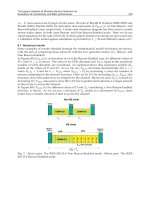
The
vibrotransporting
tray shown
in
Figure
6E-1
carries
a
mass
m. The
flat
springs
are
inclined
at an
angle
a = 10° to the
vertical.
The
coefficient
of
friction
between
the
tray
and the
mass
is
//
=
0.2. Calculate
the
minimum amplitude
of
vibrations
of
the
tray
that
will cause movement
of the
mass
m if the
vibration frequency
is 50 Hz or
314
rad/sec; calculate
the
minimal
frequency
of
vibrations
if the
vibrational
ampli-
tude
a is
about
a =
0.01
mm
that
will cause movement
of
the
mass
m.
Assume
the
vibra-
tions
are
harmonic.
FIGURE
6E-1.
TEAM LRN
7
Feeding
and
Orientation Devices
7.1
Introduction
As
we
have seen
in the
previous chapters, every automatic manufacturing machine
is
provided with
at
least
one
feeding
position.
In
this chapter
we
discuss aspects
of
feeding
for
automatically acting equipment. These automatic feeding devices
or
systems
can be
classified according
to the
form
of the fed
materials, which
can be:
Liquids
of
different
viscosities;
Powders
or
other
granular
materials;
Wires,
strips,
or
ribbons, etc.;
Rods
of
various
profiles;
or
Individual
parts,
blanks,
or
details.
In
addition,
the
specific
chemical
and
physical properties
of the
materials must
be
considered. These properties
may or may not be
exploitable
for
automatic
feeding.
Automatic
feeding
devices must usually provide
the
following
actions
and
conditions:
•
Dosing
of fluid or
continuous materials;
•
Keeping discrete items
in a
definite
arrangement
or
orientation;
•
Carrying
out the
action
at the
right moment,
at the
required place,
and as
quickly
as
possible.
Sometimes
feeding
coincides with some other process.
For
example, several
feeding
devices
can
work
in
parallel
and
bring materials
or
parts together during
feeding.
Screws
and
washers
can be
assembled during
feeding
and can be
transported together
to the
next
operation,
which would logically
consist
of
inserting
the
screw
into
a
part.
227
TEAM LRN
228
Feeding
and
Orientation
Devices
7.2
Feeding
of
Liquid
and
Granular Materials
We
begin
the
discussion with automatic
feeding
of
liquids, which includes,
for
example:
•
Automatic
filling
of
bottles, cans,
and
other containers with milk, beer, oil, dyes,
lubricants, etc.;
•
Automatic distribution
of
fuel,
dye, glue, etc.,
to
definite positions
and
elements
of
an
automatic machine;
•
Automatic lubrication
of
machine joints, guides,
shafts,
etc.
Here,
two
kinds
of
feeding
exist—continuous
and
dosewise.
Flowmeters
of
every kind provide automatic control
for
continuous feeding
of
liquids.
Such
flowmeters
were discussed
and
illustrated
in
Chapter
5.
They
are
included
in
the
control layout
and
create
feedbacks
ensuring
the
desired level
of
consumption
accuracy.
These
flowmeters are
useful
for
providing uniformity
of dye
consumption
in
automatic dyeing machines.
Industrial
painting systems
can
serve
as a
clear example
for the
strategy
of
liquid
feeding
during processing, including
a
method
for
preventing losses
of dye and for
providing
high
efficiency,
i.e., uniform coloring
of the
parts,
and
good penetration
of
the dye
into crevasses.
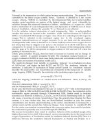
The
system shown
in
Figure
7.1
consists
of a dye
sprayer
1, a
chain transporting device
2
provided with hooks
3 on
which metal parts
4 to be
colored
are
hung.
An
electrostatic
field is
created
in the
chamber
in
which this system
is
installed
by
connecting
the
chain
to the
positive
and the
sprayer
to the
negative poles. Thus,
the
negatively charged
dye fog is
attracted towards
the
parts (while
the
chain
is
pro-
tected
by
screen
5).
Let
us
next consider
an
automatic device
for
dosewise
filling of
bottles
or
cans.
Figure
7.2
shows three states
of an
element involved
in the
process
of filling
bottles.
The
mechanism consists
of
transporting device
2
that
moves bottles
1
rightward,
dosing
cylinder
3, and
nozzle-moving cylinder
4. The
latter
first
moves nozzle
5
down into
the
bottle,
and
then
pulls
it up
relatively
slowly,
while
the
bottle
is
simultaneously
filled
with
the
liquid.
To
provide
this
movement, piston
6 is
mounted
on the
nozzle, which
also functions
as a
piston rod.
Valve
7
controls
the
motion
of
this piston inside cylin-
der 4. By
changing
the
position
of the
valve,
the
system connects
the
appropriate
end
FIGURE
7.1
Design
of an
automatic
dyeing
machine
with
electrostatic
dye
application.
TEAM LRN
7.2
Feeding
of
Liquid
and
Granular
Materials
229
FIGURE
7.2
Design
of
automatic
device
for
filling
bottles with
liquid.
of
cylinder
4 to the air
pressure.
The
upper
end of the
nozzle
is
provided with another
piston
8,
which serves
as a
pump. During
the
downstroke
of
this piston
the
liquid
is
sucked
into
the
upper
volume
of
the
doser,
and
during
the
upstroke
the
liquid
is
trans-
ferred
to the
bottle. This sequence
of
liquid displacements
is due to two
one-way valves
9
and 10.
Thus,
filling
of
the
bottle occurs
as the
nozzle
is
slowly pulled
out
of
the
bottle.
This
action
sequence prevents bubbling,
foaming,
and
dripping
of
the
liquid.
The
lifting
speed
of the
nozzle
is
kept equal
to the
rate
at
which
the
liquid level rises,
so
that
its
tip
stays below
the
liquid during
filling. It
follows
from
this description
that
the
volume
of
the
dosing cylinder must equal
the
volume
of the
bottle.
The first
state
of
the
mech-
anism shown
in the figure (I) is the
situation
at the
moment when
the
bottle
is
brought
into
position under
the filling
mechanism
and the
nozzle begins
its
movement down-
ward.
In
state
II the
nozzle
has
reached
the
lowest point
and
dosing cylinder
3 is filled
with
the
liquid.
The
bottle
is
still empty.
In
state
III of the filling
process
the
nozzle
is
about
halfway
out
of
the
bottle,
the
bottle about
half
full,
and the
dosing cylinder about
half
empty.
The
bottle-filling
process
may be
carried
out
while both
the
bottles
and
the
dosing devices
are in
continuous motion.
Now
we
consider
an
example
of
feeding
granular materials
in
portions. This situ-
ation
is
typical,
for
instance,
of
casting, molding,
or
pressing
from
powders
or
granu-
lar
material.
A
plan
of
this sort
of
device
is
shown
in
Figure 7.3.
Rotor
2
rotates around
immobile
axle
1.
The
rotor
consists
of a
system
of
automatic
scales
that
include levers
3,
force
sensors
4, and
pockets
5 in
which bowls
6 are
located. Hopper
7 is
placed
at
TEAM LRN
230
Feeding
and
Orientation
Devices
FIGURE
7.3
Plan
for
automatic
weighing
machine
for
granular
material.
one
position above
the
rotor. This hopper
has
gate
8
controlled
by two
electromagnets
9
and 10,
which receive commands
from
control unit
12
connected
to
force
sensors
4.
An
empty pocket
5
with
bowl
6
stops under sleeve
11.
At
this moment,
force
sensor
4
produces
a
signal through control unit
12
which actuates electromagnet
9 to
open gate
8.
When
the
weight
of the
material reaches
the
value
the
scale
is set
for,
sensor
4
pro-
duces another command
to
energize electromagnet
10 and
close
the
gate.
At
this
moment
the
rotor rotates
for one
pitch, putting
the
next empty pocket under
the
hopper.
The filled
pockets
may
then
be
handled
and
used
for
specific
purposes.
We
have just considered
an
interrupted
feeding
process.
Belt
conveyors, which
are
useful
for a
wide range
of
capacities,
are
often
used
for
continuous
feeding
of
granu-
lated matter.
An
effective
feeding
tool
is the
vibrating conveyer described
in
Chapter
6.
By
changing
the
vibrational
amplitudes
or
frequency,
the
feeding
speed
can be
tuned
very
accurately.
The
last mechanism
we
consider
for
feeding
this kind
of
material
is the
auger
or
screw
conveyor,
a
design
for
which
is
presented
in
Figure 7.4. Screw
1
rotates
on its
FIGURE
7.4
Screw
conveyor
for
feeding
granular
material.
TEAM LRN
7.3
Feeding
of
Strips,
Rods,
Wires,
Ribbons,
Etc.
231
shaft
2
which
is
driven
by
motor
3 via
transmission
4
(here
a
belt transmission
is
shown).
The
screw
is
located inside tubular housing
5,
which
has
inlet
and
outlet sleeves
6 and
7,
respectively.
The
material
is
poured into sleeve
6 and due to
rotation
of the
screw,
is
led to
sleeve
7
where
it
exits
for
subsequent
use or
distribution. Obviously,
the
speed
of
the
screw's rotation
defines
the
rate
of
consumption
of the
material.
7.3
Feeding
of
Strips,
Rods,
Wires,
Ribbons,
Etc.
Linear
materials
are
often
used
in
manufacturing. Their advantage
is
that
they
are
intrinsically oriented.
(We
will discuss orientation problems later.) Thus,
the
feeding
operation requires relatively simple manipulations. Indeed,
in
unwinding wire
from
the
coil
it is
supplied
on,
only
one
point
on
this wire needs
to be
determined
to
com-
pletely
define
its
position. Thus,
an
effective
technical solution
for
feeding this kind
of
material
is two
rollers gripping
the
wire (strip, rod,
etc.),
from
two
sides
and
pulling
or
pushing
it by
means
of the
frictional
forces
developed between them
and the
mater-
ial.
We
have already used this approach
in
examples considered
in
Chapter
2
(for
example, Figures
2.2 and
2.4). Continuous rotation
of the
rollers provides,
of
course,
continuous
feeding
of the
material, which
is
effective
for
continuous manufacturing
processes. However,
for a
periodical manufacturing process,
feeding
must
be
inter-
rupted.
One way to do
this
is
based
on the use of a
separate drive controlled
by the
main controller
of the
machine. Such
an
example
was
discussed
in
Chapter
2.
When
the
feeding time
is a
small
fraction
of the
whole period,
this
solution
is
preferable.
When
the
feeding time
is
close
to the
period time,
the
solution presented
in
Figure
7.5
may be
proposed. Here, lower roller
1 is
always driven,
and
upper roller
2 is
pressed
against roller
1 by
force
Fto
produce
the
friction
required
to
pull material
3. The
force
F
can be
produced
by a
spring
or
weight. (The latter needs more room
but
does
not
depend
on
time
and
maintains
a
constant
force.)
Roller
1 has a
disc-like
cam 4,
which
protrudes
from
the
roller's
surface
for a
definite angle
0.
Thus, during part
of the
rota-
tion
of the
driving roller
1,
i.e., that corresponding
to
angle
0,
upper roller
2
will
be
dis-
connected
from
the
wire (rod, strip, etc.)
3, and the
mechanism will therefore stop
FIGURE
7.5
Frictional
roller
device
for
continuous
feeding
of
wires.
TEAM LRN
232
Feeding
and
Orientation
Devices
pulling
or
feeding
the
material.
Obviously,
other means
to
disconnect
the
roller
are
available;
for
instance,
a
mechanism
to
lift
slider
5.
Another
sort
of
device
for
interrupted
feeding
of
materials
is
also based
on
creat-
ing
frictional
forces;
however, feeding
is
done
by
pure pulling
and
pushing
of
the
mate-
rials.
Let us
consider
the
scheme
in
Figure 7.6. Here, lever
1 is
pressed
by
force
Q
against
strip
3 by
means
of
spring
2.
Strip
3 is
clamped between
the
lever
and
surface
4. Due
to
this pressure,
frictional
forces
F
occur
at
points
A and
A'
(we
assume that
the net
forces
acting
on the
surfaces
can be
considered
at
these
points).
Quantitative relations
between
the
forces
are
derived
from
the
following equilibrium
equations
written with
respect
to
lever
1:
Here
n
=
frictional
coefficient
between
the
materials
of the
strip
and of the
lever
at
point
A.
We
assume that
the
same condition exists
at
point
A'.
The
four
Equations
(7.1)
contain
four
unknown
quantities:
N,
N
0
,
F,
and
F
0
.
By
substituting Equation
4
into Equa-
tion
3 we
obtain
By
substituting Equation
(7.2),
into
the first
equation,
we
obtain
From
Equations
(2) and (4) it
follows
that
The
derived results reveal
a
very important
fact:
when
FIGURE
7.6
Frictional clamping device
(lever
type).
TEAM LRN
7.3
Feeding
of
Strips,
Rods,
Wires,
Ribbons,
Etc.
233
no
spring
(no
force
Q)
is
needed—the
system
is
self-locking.
The
harder
we try to
pull
the
strip,
the
stronger
it
will
be
clamped.
The
force
the
device applies
to the
strip equals
2F
because there
are two
contact points
A and
A'
where
the
strip
is
caught,
and
fric-
tional
forces
F
affect
the
strip
from
both
sides.
The
structure shown
in
Figure
7.7
works analogously. Here, strip
1 is
clamped
between surface
2 and
roller
3. To
produce clamping
forces,
the
roller
is
pushed
by
force
N
c
(due
to a
spring
not
shown
in the figure). The
equilibrium equations with
respect
to the
immobile rollers
3
have
the
following
forms:
Pay
attention
to
inequalities
3 and 4 in the
latter system
of
equations.
The
friction
force
at
a
point
"B"
is
determined
by the
pulling
force
developed
by the
device, while
the
friction
force
at a
point
"A"
fits the
equilibrium
of all the
components
of the
force.
We
assume that
the
frictional
coefficients
at
points
A, B, and C are
identical.
The
unknown forces here
are
F
A
,
N
A
,
F
B
,
and
N
B
.
Substituting Equations
3 and 4
into Equa-
tions
1 and 2, we
obtain
From
this
it
follows
that
and
Finally,
we
have
FIGURE
7.7
Frictional clamping device
(roller
type).
TEAM LRN
234
Feeding
and
Orientation
Devices
Obviously,
when
self-locking occurs,
and no
N
c
force
(no
spring)
is
needed
to
lock
the
strip, wire. etc.
The
devices
in
Figures
7.6 and 7.7
must
be
designed
so
that
they
do not
reach
the
self-locking
state,
to
ensure easy release
of the
material when
the
direction
of the
applied
force
is
changed. Thus,
the
relations usually should
be
The
principles described above allow
an
effective
feeder
to be
designed.
A
possi-
ble
layout
is
shown
in
Figure 7.8.
Here,
two
identical units
I and II
work
in
concert
so
that
one
(say,
I) is
immobile
and the
other carries
out
reciprocating movement, with
the
length
L
of a
stroke
equal
to the
length
L of the fed
section
of the
strip, etc. Each
unit consists
of
housing
1, two
rollers
2
pressed against inclined surfaces inside
the
housing,
and
spring
3
exerting
force
N
c
.
The
housings have holes through which
the
strip, ribbon, etc., passes.
How
does this device act? First, unit
II
moves
to the
right.
Then
the
material
is
clamped
in it due to the
direction
of the
frictional
force
acting
on
the
rollers, while
in
unit
I the
material (for
the
same reason) stays unlocked
and its
movement
is not
restricted.
As a
result,
the
material
is
pulled through unit
I
while
clamped
by
unit
II.
Afterwards,
unit
II
moves backward
the
same
distance.
This time,
the
frictional
forces
are
directed
so
that unit
I
clamps
the
material
and
resists
its
move-
ment
to the
left.
Unit
II is now
unlocked
and
slides along
the
strip
as it
moves.
At the
end of the
leftward
stroke,
the
device
is
ready
for the
next cycle.
In the
cross
section
A-A
in
Figure
7.8
another version
of the
clamps
is
shown. Here, instead
of two
rollers
(which
are
convenient
for
gripping
flat
materials), three balls
in a
cylindrical housing
are
shown. This solution
is
used when materials with
a
circular cross section
(wires,
rods, etc.)
are
fed.
Finally,
we
show another
strip-feeding
device which
is
suitable when
the
time
r
during which
the
material
is
stopped
is
relatively short
in
comparison
to the
period
T;
that
is,
T»T.
The
mechanism
is
shown
in
Figure 7.9a)
and
consists
of a
linkage
and
TEAM LRN
7.4
Feeding
of
Oriented
Parts
from
Magazines
235
FIGURE
7.9 a)
Geared
linkage
as a
drive
for
roller
friction
feeder
for
interrupted
feeding;
b)
Speed
and
angle changes versus
time,
with this
device.
gears. Crank
1 is a
geared wheel, rotating around immobile center
O^
whose geomet-
rical center
A
serves
as a
joint
for
connecting
rod 2. The
latter drives lever
3. A
block
of
gear wheels
4 and 5 is
assembled
on
joint
B.
Wheel
5 is
engaged with driven wheel
6.
The sum of the
links'
and
wheels' rotation
speeds
(when
the
tooth numbers
are
chosen properly) allows this mechanism
to
have
a
variable ratio
o}
G
/o)
lt
which
is
shown
graphically
in
Figure 7.9b). During rotation interval
At,
wheel
6 is
almost immobile
(the
backlash that always exists
in
gear engagement makes this stop practically
absolute).
Imagine
now
strip
7 fed by
rollers
8
driven
by
wheel
6, and you
have
an
inter-
rupted
feeding,
although driving link
1 is
always rotating. Because
of
the
smooth speed
and
displacement curves,
the
dynamics
of
this
mechanism
are
rather good.
7.4
Feeding
of
Oriented Parts
from
Magazines
There
are
essentially
two
approaches
to the
parts-feeding problem:
first,
feeding
of
previously
oriented parts; second, feeding
from
a
bulk supply.
We
begin with
the first:
feeding
of the
previously oriented parts.
For
this purpose
some classical solutions
and
several subapproaches exist. They will
be
discussed here
on the
basis
of
some practical examples.
Example
1
Electronic
elements such
as
resistors, capacitors,
and
some types
of
diodes
are
shaped
as
shown
in
Figure
7.10a).
To
make
the
feeding
of
these parts
effective,
they
are
TEAM LRN
236
Feeding
and
Orientation Devices
FIGURE
7.10
Separate
parts arranged
for
automatic
feeding
in a
band-like
form,
by
means
of
tapes.
assembled into
a
band
by
means
of
tapes
or
plastic ribbons
1
(Figure
7.10b).
The
leads
2
of
the
resistors
3 are
glued between
two
tapes,
making
a
band
convenient
for
storage
(wound
on a
coil),
for
transportation
to the
working position
of
an
automatic machine,
and for
automatic
feeding.
Obviously, additional orientation
of the
resistors
is
unim-
portant.
It is
relatively easy
to
bring them
to the
appropriate position accurately enough
so
that
a
gripper
or
other tool
can
handle them.
Example
2
Very
often
in
mass production, parts
are
stamped
out
from
metal
or
plastic strips
or
ribbons.
To
make them convenient
for
further
processing,
the
following
method
can
be
used.
Let us
consider
a
detail made
of a
thin metal strip,
as
shown
in
Figure
7.1
la).
It
can
also
be
handled
in a
band
form;
however,
in
this case
the
procedure
is
simpler
because this
form
can be
made directly
by
stamping
a
strip (without additional
effort).
FIGURE
7.11
Stamping
sequence
to
make
a
product
convenient
for
automatic
handling,
a)
Final
product—a
contact
bar of an
electromagnetic
relay;
b)
Intermediate
processing
stages;
c)
Cross
section
of the
contact
rivets.
TEAM LRN
7.4
Feeding
of
Oriented
Parts
from
Magazines
237
Figure
7.1
Ib)
shows
how
this
can be
done
for
a
contact
bar of an
electromagnetic relay.
Platinum-iridium
contacts
are
riveted
in the two
small
openings
in the
split
end
of
the
bar
(see cross section
in
Figure
7.lie)).
This riveting
is
much more convenient
to do
while
the
bars
are
together
in a
band-like structure,
as in the
illustration. Strip
1 is
introduced into
the
stamp.
It has a
certain width
b and is
guided into
the
tool
by
sup-
ports
2. At
line
A the
openings (blackened
in the
illustration)
are
cut.
In the
next step
the
split
end of the bar is
shaped
and
next
the
lower
end is
completed. Thus, section
LJ
is
needed
to
produce
the
bar. From line
B the
band-like semiproduct
is
ready.
However,
the
bars
are
kept connected
by two
cross-pieces
3 and 4. The
contact
is
riveted
in
section
L,,
either
on the
same
or
another machine.
An
example
of
this process
is
explained
in
Chapter
8.
Obviously,
in
either case
no
special
efforts
are
needed
to
bring
the bar
oriented
to the
riveting position. When
the
contact
is in its
place
the
bars must
be
separated. This happens
at
line
C by
means
of two
punches which
cut the
remain-
ing
cross-pieces (blackened spots
in the
illustration).
The
above examples (Figures
7.10
and
7.11)
are
typical high-productivity automatic
processes, where automatic
feeding
of
parts must
be as
rapid
as
possible.
Therefore,
the
contrivances described above
are
justified.
However,
often
the
processing time
is
relatively
long
and the
automatic operation does
not
suffer
much
if
feeding
is
simpli-
fied.
This
brings
us to the
idea
of
hoppers
or
magazines.
The
classical means
of
automat-
ing
industrial processes
use a
wide range
of
different
kinds
of
hoppers, some
of
which
are
discussed
below.
Tray
hoppers
are
manually loaded with parts which then slide
or
roll under
the
influence
of
gravity,
as
shown
in
Figure
7. 12. A
shut-off
device
is
installed
at the end
of
the
tray
to
remove only
a
single part
from
the flow of
parts
on the
tray.
The
design
of
these devices depends,
of
course,
on the
shape
of the
part they must handle.
The
rough
estimation
of
the
moving time along
the
inclined tray
was
considered
in
Chapter
2,
Section
2.1.
A
phenomenon which must always
be
taken into account
in
designing tray hoppers
is
seizure,
which
is
schematically illustrated
in
Figure
7.13.
To
ensure reliable move-
ment
of the
part along
the
tray,
one
must keep
the
seizure angle
j
as
large
as
possible.
This angle
depends
on the
ratio
L/D
(the length
L of the
part
to its
diameter
or
width
FIGURE
7.12
Tray
hoppers:
a)
Usual
type;
b)
Tortuous
slot
shape
for a
hopper.
TEAM LRN
238
Feeding
and
Orientation
Devices
FIGURE
7.13
Graphical
interpretation
of
seizure
of
parts
in a
tray.
D),
and
values
of
L/D
< 3 are
good enough.
In
practice
the
clearance
A
must
be
chosen
correctly
to
prevent seizure. From Figure
7.13
it
follows
that
which,
by
substituting
yields
To
avoid seizure
in the
design shown
in the
figure,
the
seizure angle
7
must
be
larger
than
the
friction angle
p,
which
means
Here
ju
is the
factional
coefficient
between
the
tray sides
and the
part.
Expressing
cos 7
through
tgy,
we
obtain
the
clearance
from
Equation
(7.14)
in the
following
form:
Contrary
to
case
a),
case
b) in
Figure 7.12
is
suitable
for
parts with
L/D>3
because,
due to the
tortuous slot shape,
the
part cannot
fall
sideways
and
achieve dangerous
values
of
angle
7.
This design
is
useful
for
many other applications
in
machinery where
seizure
can
take place.
The
length
of
the
tray depends, obviously,
on the
processing time
and
must provide
a
reasonable amount
of
parts without
frequent
human interference.
To
elongate
the
tray
and
increase
the
number
of
parts stored
in it,
zigzag
or
spiral trays
are
used (see
Figures
7.14a)
and
b)).
The
zigzag hopper,
in
addition, limits
the
falling
speed
of
parts,
which
is
sometimes important,
for
instance,
when they
are
made
of
glass.
Tray
hoppers
are
sometimes modified into
a
vertical sleeve
or
channel,
as
shown
in
Figure 7.15.
In
case
a),
hollow cylindrical parts
are
fed,
and in
case
b), flat
parts. Here
we
see the
shut-off
mechanisms:
a
cylindrical pusher
in a) and a flat
slider
in
b),
which
carry
out
reciprocating motion.
The
pace
of
motion
is
dictated
by the
control system;
however,
it
must allow
the free
fall
of the
parts
in the
hopper.
It may be
possible
to
TEAM LRN
7.4
Feeding
of
Oriented
Parts
from
Magazines
239
FIGURE 7.14
High-volume
a)
zigzag
and
b)
spiral
hoppers.
FIGURE
7.15
Examples
of
vertical
sleeve,
tube,
or
channel
hopper.
drive
the
parts
in the
hopper pneumatically
or
with
a
spring.
The
latter
is
generally
used
in
automatic
firearms. To be
reliable,
cut-off
of the fed
parts requires
a
certain
degree
of
accuracy
in the
mechanism. Thus,
the gap A is
restricted
to a
value
of
about
0.05
to
0.1
mm, the
value
^
~
h -
(0.05
to
0.1
mm),
and h
^
0.5 mm.
Vertical
box
hoppers
are
more compact. Figure
7.16
illustrates several such hoppers.
Case
a)
consists
of box 1 in
which
the
blanks
are
loaded
in
several layers, tray
2, and
shut-off
pusher
3
which takes
the
blanks
out
of
the
hopper
by
pushing along their axis.
Viewb)
shows
the
cross section
of
this hopper,
and
here agitator mechanism
4 is
shown.
The
purpose
of
this mechanism
is to
prevent creation
of a
bridge
of
blanks which dis-
turbs
their
free
movement towards
the
outlet. Case
c)
shows
a
similar hopper where
FIGURE 7.16
Vertical
box
hopper.
TEAM LRN
240
Feeding
and
Orientation
Devices
shut-off
mechanism
2
pushes
the
blanks sideways, bringing them
from
the
bottom
of
the box to
channel
5.
For
flat
details
or
blanks, horizontal
box
hoppers
are
used.
Two
examples
are
illus-
trated
in
Figure 7.17.
The
height
of
these details
may not be
more
than
50-70%
of
their
width
or
diameter. Case
a)
consists
of
inclined tray
1
provided with edges
2 and
agita-
tor 3. The
parts move
by
gravity.
The
oscillations
of the
agitator destroy
any
bridges
that might impede movement
of the
parts.
In
case
b) the
hopper consists
of a
hori-
zontal circular
box
with rotating bottom
1,
circular wall
2, and
agitator
3.
Friction
between
the
bottom
and the
blanks advances them
to
outlet
4. The
danger
of
seizure
appears here, also.
The
layout shown
in
Figure
7.18
explains
the
geometry
of
this phe-
nomenon, which happens when
the
angle
a
approaches
the
friction
angle, i.e.,
Here,
p is the
friction
angle,
and
n
is the
coefficient
of
friction.
FIGURE
7.17
Horizontal
box
hoppers:
a)
Gravity
drive;
b)
Friction drive.
FIGURE
7.18
Graphical
interpretation
of
parts
seizure.
TEAM LRN
7.4
Feeding
of
Oriented
Parts
from
Magazines
241
Obviously,
and
Thus,
by
substituting Equations
(7.18)
and
(7.19)
into Equation
(7.17),
we
obtain
and
from
here,
and
This
formula
defines
the
width
of the
tray
at
which
two
parts cause seizure.
For n
parts
in
a
row,
we
analogously derive
and
Finally,
we
consider
a
hopper used
for
feeding
parts
in an
automatic machine
for
welding
aneroids
(an
example
is
described
in
Chapter
2).
The
hopper
is
shown
in
Figure
7.19a),
and
consists
of
cylindrical housing
1
having spring
2 for
lifting
membranes
3
previously
fastened
pairwise
at,
say, three points
by
point welding.
At the top of the
hopper
a
shut-off
device
is
installed. This device
consists
of two
forks
4 and 5,
each
of
which
has two
prongs
41 and 42, and 51 and 52, and
rotates around pins
6 and 7,
respec-
tively.
Prongs
41 and 51 are
connected
by
spring
8. (In
Figure
7.19b)
the
forks
are
shown
separately
to
facilitate
understanding.)
The
prongs
are
seen
in
cross section
at the
upper
part
of
the
hopper.
Note
that
the
prongs
are
located diagonally, i.e.,
the
upper right
and
lower
left
belong
to
fork
5, and the
upper
left
and
lower right
to
fork
4.
When situated
as
in
Figure 7.19 view
I,
prongs
41 and 51
hold
the
upper aneroid
by its flange
while
spring
2
lifts
the
column
of
blanks. Magnetic
gripper
9 in the
meantime approaches
the
uppermost blank.
At
this
moment
force
F is
applied simultaneously
to
forks
4 and 5,
moving
them
as
arrows
a and b
show (Figure
7.19b)).
This brings
the
shut-off
device
to
the
position shown
in
view
II.
Prongs
41
and
51
move apart while prongs
42 and 52 are
pushed together, holding
the flange
of
the
penultimate aneroid
and
leaving
the
upper-
most aneroid
free
to be
taken
by the
magnetic gripper.
We
showed
in
Chapter
2
that
welding
one
aneroid takes about
30
seconds. Keeping about
120
blanks
in the
hopper
will
allow
1
hour
of
automatic
work
without human intervention.
The
thickness
of one
TEAM LRN
242
Feeding
and
Orientation Devices
FIGURE
7.19 Tube-like hopper
for an
automatic machine
for
welding
aneroids,
a)
General
view
of the
device;
b)
Plan view
of the
shut-off
mechanism.
aneroid
is
about
5 mm:
therefore,
the
height
of the
column
of
blanks
is
about
600 mm.
Together
with
the
compressed spring,
the
hopper
is
about
750 mm
long.
7.5
Feeding
of
Parts from Bins
In
the
feeding
devices discussed
in
this section,
the
parts
are fed
from
bulk supplies.
The
device must issue
the
parts
in the
required amount
per
unit
time
and, what
is
most
important,
in a
definite
orientation. Feeding bins
can
issue
the
parts
by the
piece,
by
portions
of
parts,
or as a
continuous
flow
of
parts.
We
illustrate each approach here.
First,
the
pocket hopper will
be
considered.
A
typical
feeder
of
this kind
is
shown
in
Figure
7.20. This device consists
of
rotating disc
1
placed
at the
bottom
of
housing
2.
The
whole device
is
tilted,
and
outlet
channel
3 is
located
at the
upper point
of the
bottom. Disc
1 is
driven
by,
say, worm transmission
4. The
disc
is
provided with pockets
of
a
shape appropriate
to the
parts
the
device handles. Figure 7.20 shows three ways
of
locating these pockets.
The
point
is
that, depending
on the
1/d
ratio,
the
parts
find
TEAM LRN
7.5
Feeding
of
Parts
from
Bins
243
FIGURE
7.20 Pocket
hopper:
a)
Pockets
for
elongated
details;
b)
Pockets
for
short
details;
c)
Radially oriented pockets.
their
preferred
orientation
so as to
minimize
the
resistance
forces
appearing during
their motion. When
l/d»l
this
preferred
orientation
is
along
the
chord
of the
disc.
The
larger
the
ratio,
the
more parts
are
oriented
in
that way.
Naturally,
in
this case
the
pockets
should
be
made
as
shown
in
Figure
7.20a).
For
l/d=2
the
pockets
are
formed
as in
Figure
7.20b).
To
increase
the
number
of
pockets
on the
disc, they
may be
ori-
ented radially
(Figure
7.20c)),
which increases
the
productivity
of
the
device. However,
to
compel
the
parts
to
fall
into radial pockets,
the
surface
of the
disc must
be
appro-
priately shaped with special radial bulges.
The
maximum rotational speed
of the
disc
is
determined
by the
falling
speed
of the
parts into outlet tray
3. For
this purpose
the
length
of the
in
case
a) and its
width
in
cases
b) and c)
must
be
great enough
to
provide clearance
A.
Thus,
for the
three types
a),
b),
and c),
respectively,
The
peripheral speed
V
of
the
disc
can be
estimated
from
the
formula
Here,
g is the
acceleration
due to
gravity,
and h is the
height
the
part must
fall
to get
free
of the
disc
(obviously,
h
equals
the
thickness
of the
part
or d, its
diameter).
The
next kind
of
feeder
we
consider
is the
so-called
sector
hopper.
This device
is
shown
in
Figure
7.21
and
consists
of
an
oscillating sector
1
provided with slot
2,
housing
3,
outlet tray
4, and
usually
shut-off
element
5. The
parts
6 are
thrown
in
bulk into
the
bowl
of the
housing. When
the
sector turns
so
that
the
slot
is in its
lower position,
the
slot
is
immersed
in the
parts
and
catches
a
certain number
of
them
by
chance
as it is
lifted
by the
sector. These
then
slide
out
along
the
slot
and
into tray
4. The
shape
of
the
slot must
be
suitable
for the
shape
of the
parts handled
by the
device (see Figure
7.22).
To
permit
free
movement
of
blanks
in the
slot
and
optimum
feeding
and
orien-
TEAM LRN
244
Feeding
and
Orientation
Devices
FIGURE
7.21
Sector-type
hopper.
FIGURE
7.22
Shapes
of
slots
for
differently
shaped details.
tation,
the
following
empirical relationships between
the
dimensions
of
the
parts
and
the
slot parameters
are
recommended:
A
very similar
feeding
device
is the
knife hopper,
a
representative
of
which
is
shown
in
Figure 7.23.
It
consists
of
reciprocating
knife
1
which slides vertically beside inclined
plate
2,
which
has a
slot
on its
upper edge.
Bowl
3
also serves
as a
housing,
and
shut-
FIGURE
7.23 Knife-type
hopper.
TEAM LRN
7.5
Feeding
of
Parts
from
Bins
245
off
wheel
4
rotates
in the
direction opposite
to
that
of the
parts
movement. When
the
knife
moves down
it is
immersed
in the
supply
of
blanks.
In
moving upward
it
catches
some
of
them and,
at the
upper position
of the
knife,
these blanks
fall
into
the
slot.
Those
that
are
successful
in
becoming oriented correctly
will
proceed
in the
slot under
the
shut-off
wheel.
The
others will
be
resumed
by
this wheel back into
the
bulk
for a
new
attempt.
The
sliding time
of
an
item along
the
slot
in
both
the
latter
feeders
can be
estimated
as
shown
in
Chapter
3,
Section 3.1.
To
provide
the
required productivity,
the
length
L
of
the
sector
or the
knife
usually
has the
following relation
to the
blank's length
I:
Here
/ is the
length
of the
blank
in the
direction
of
sliding when
it is
properly oriented.
The
feeding
rate
of
these devices
is
limited
by the
acceleration
of the
knife
or
sector
as it
reaches
its
upper position.
Obviously,
this acceleration
a
0
must
be
smaller than
g;
otherwise
the
blanks will jump
out
of
the
slot
or
lose their orientation.
It is
easy
to
esti-
mate
the
value
of the
acceleration
of the
knife
or
sector.
Let us
describe
the
displace-
ments
of the
knife
by the
following
expression:
Thus,
the
acceleration
a
here
has the
form
and the
maximum value
of the
acceleration
a^
has the
value
We
must ensure that
Here,
s
0
is the
amplitude
of the
knife
or
sector
(at the
point farthest
from
the
axis
of
rotation),
and
(o
is the
frequency
of
oscillation
in
rad/sec—or
in
rpm
we
have
These
two
feeders
are
examples
of
devices
that
issue
parts
in
portions.
The
number
of
blanks
fed per
unit time
is a
statistical average
and can be
estimated experimentally
to
determine
the
productivity
of the
machine that
the
feeder
serves.
To
avoid interrup-
tion
of
processing
due to
lack
of
blanks,
the
outlet tray should
be
long enough
to
hold
about
25-30
blanks,
to
compensate
for
statistical deviation
in the
number
of
parts fed.
The
third kind
of
feeding that provides
a
continuous
flow of
parts
is
vibrofeeding.
We
have already described
the
phenomenon
of
vibrotransportation
in
qualitative terms
in
Chapter
6,
Section 6.4.
A
typical medium-sized
vibrofeeder
is
illustrated
in
Figure
7.24.
The
device consists
of
bowl
1,
whose internal surface
is
spirally grooved.
The
bowl
is
fastened
to
platform
2,
which
is
supported
by
three slanted elastic rods
3. The
rods
are
fastened
to the
platform
and to
base
4 by
shoes
5 and 6, so
that
the
projection
of
the
rods
on the
horizontal plane
is
perpendicular
to the
bowl's radius.
The
platform
is
TEAM LRN
246
Feeding
and
Orientation Devices
FIGURE
7.24
Vibrofeeder.
General view.
FIGURE
7.24a)
General view
of a
vibrofeeder with
its
controller. This device
is
driven
by an
electromagnet, like
that
shown schematically
in
Figure 7.24. This
is an
industrial device
and can be
used
for
feeding
parts
in
concert with
an
automatic manufacturing machine.
(Aylesbury
Automation Ltd., Aylesbury, England)
TEAM LRN
7.5
Feeding
of
Parts
from
Bins
247
vibrated
by
electromagnet
7
fastened
in the
middle
of
base
4. The
electromagnet
is
made
of
core
8 and
coil
9. To
prevent transfer
of
vibrations
to the
system
or
machine
on
which
the
feeder
is
mounted,
the
latter
can be
installed
on
three springs
10, of
rel-
atively
low
stiffness.
Pin
11
restrains
the
feeder
from
moving
too
much. When coil
9 of
magnet
7 is
energized
by
alternating current (usually
the
standard
frequency
of 50 Hz
is
used),
an
alternating
force
pulls armature
12.
This
force
causes spiral oscillation
of
the
bowl (because
of
inclined springs
3).
Under certain conditions
the
alternating accel-
eration
of
this movement causes
the
parts
in the
groove
to
proceed,
as we
showed
earlier
for a
vibrating tray (Figure
6.22).
Figure
7.25 shows
a
diagram
of
forces
acting
on an
item located
in the
groove
of a
spirally
vibrating bowl.
The
slope
of
springs
3 is
indicated
by
angle
7, and
that
of the
groove
by a.
Then
we
denote
y-a=/3.
This diagram describes
both
straight
and
spiral
vibrofeeding
and
differs
from
that
shown
in
Figure 6.22
by the
angle
ft
between
the
groove
and the
direction
of
oscillation. Corresponding
to the
labels
in
Figure 7.25,
the
balance equations
for the
item
in the
groove have
the
following
form:
where,
P
=
mg=weight
of the
item,
m =
mass
of the
item,
F=
frictional
force
between
the
groove
and the
item,
N=
net
force
normal
to the
groove,
x,
y -
displacement
of
the
item along
the x- and
y-axes,
respectively.
FIGURE
7.25
Forces
acting
on an
item
placed
on the
tray
of a
vibrofeeder.
TEAM LRN
248
Feeding
and
Orientation Devices
If
S is the
actual
displacement
of the
item,
then
x = S cos
/?
and y = S sin ft.
Obvi-
ously,
F=juNifju
is the
frictional
coefficient.
We
now
show
the
development
of an
expression
for
estimating
the
productivity
of
a
vibrofeeder.
We
begin
with
considering
the first
half-period
of
the
oscillation
(section
EM
in
Figure
7.25a),
where
S
>
0 and S
<
0.
From (7.31) follows:
Substituting
F=juN
into (7.32)
and
excluding
AT
we
obtain:
For the
second
half-period (section
EK in the
same
figure),
where
S
<
0 and S
>
0 we
derive
from
(7.31)
the
following
equations:
and
correspondingly,
FIGURE
7.25a)
Displacement, speed
and
acceleration
of the
vibrofeeder's
bowl
for two
different
oscillation
amplitudes:
1)
There
is
practially
no
backslide
of the
item
on the
groove;
2)
There
is
backslide
of the
item.
TEAM LRN
7.5
Feeding
of
Parts
from
Bins
249
FIGURE
7.25b)
Critical
acceleration
for 1)
positive
displacement
and 2)
Negative
displacement
of the
bowl
for
different vibration
amplitudes
a and
friction
coefficients
ju.
The
relation between
the
concepts introduced
here—displacement
of the
bowl
S,
its
acceleration
S,
and
critical values
of the
acceleration causing
the
body's slide rela-
tive
to the
bowl
S
cr
and
S
cr
'—are
shown
in
Figure 7.25a). Attention must
be
paid
to the
fact
that these critical values depend only upon
the
geometry
of the
feeder
and
fric-
tion properties
of the
contacting materials.
Finally,
we
give visual representations
of the
dependences
(7.33)
and
(7.33a). These
representations
are
made
for
the
case when
the
angle
a
changes
from
0° to 5° and
angle
/3
changes
from
30° to
35°.
The
commands
for the
illustrations
are
given
in
MATHEMATICA
language.
gl=Plot3D[9.8*
(Sin[a]+m*
Cos[a])/(m*
.5+.8G6),
{a,0,.15},{m,.2,.8},AxesLabel->{"a","m","s""}]
g2=Plot3D[9.8*
(Sin[a]-m* Cos[a])/(m*
.5 86G),
{a,0,.15},{m,.2,.8},AxesLabel->{"a","m","s""}]
We
can now
proceed
to
calculations
of
the
items
displacement.
From
the
curves
in
Figure
7.25a)
it
follows
that
the
time
t
it
when
the
slide begins (section
EM),
and the
groove
lags behind
the
item,
is
defined
as
At
this time
the
speed
V
0
of the
item (and
the
bowl)
is
defined correspondingly:
Thus,
the
slide begins with this speed
and is
under
the
influence
of
friction
force
F=-jum(g-y)
acting backwards.
We
simplify
this definition
for our
engineering pur-
poses
to a
form
F=-jum(g
-
S
cr
sin
ft).
This
force
causes deceleration
W=
-fi(g-
S
cr
sin/7).
(This
assumption gives
a
lower estimation
of the
displacement, while
the
higher esti-
TEAM LRN