Understanding And Applying Machine Vision Part 3 potx
Bạn đang xem bản rút gọn của tài liệu. Xem và tải ngay bản đầy đủ của tài liệu tại đây (318.96 KB, 25 trang )
Figure 4.23
Early system from Gould Electronics providing two-dimensional vision to
guide robot for assembly operation.
Figure 4.24
Early system from Machine Vision International provides correction to
six degrees of freedom associated with position of car as it installs
windshield.
Page 61
TABLE 4.6 Machine Vision, Robotic Related
Manipulation of Separated
Workplaces on Conveyors
Bin Picking Manipulation of
Manufacturing
Process
Assembly
Workplaces lying
Stably on belt
Workplaces hung
on hooks
partially
constrained
Workpieces
completely
random spatial
organization
Workplaces
highly
organized and
separated
Workplaces
partially
organized
spatially and
unseparated
Finishing, sealing,
deburring,
cutting, process
control, flash
removal, liquid
gasketing
In-process
Inspection
Fastening, spot
welding,
riveting, arc
Welding, bolting,
screwing,
nailing, gluing,
stapling
Fitting, parts
presentation
Mating of parts
Several analyses of applications that have been conducted suggest that approximately 42% of the applications relate to
inspection (gaging, cosmetic, and verification), 45% to visual servoing location analysis of which robot guidance is
only one application, and 13% to part identification and recognition. Significantly, robot vision applications often
require systems capable of inspection in addition to guidance.
4.4—
Overview of Generic Machine Vision Benefits and Justification
The opportunities for machine vision are largely in inspection and assembly operations. Even in the latter case, many
of the applications will involve inspection (e.g., of tasks), verification, flaw detection, and so on. In conjunction with
such tasks, people are only 70–85% effective, especially when dealing with repetitive tasks. According to researchers
at the University of Iowa, people asked to perform the visual sorting task of picking out a minority of black Ping-Pong
balls from a production line of white ones allowed 15% of the black balls to escape. Even two operators together were
only about 95% effective.
Page 62
People have a limited attention span, which makes them susceptible to distractions. People are also inconsistent.
Individuals themselves often exhibit different sensitivities during the course of a day or from day to day. Similarly,
there are inconsistencies from person to person, from shift to shift, and so on. The eye's response may also be a
performance limiter.
However, people offer some advantages over machine vision. People are more flexible and can be trained for many
tasks. People can make adjustments to compensate for certain conditions that should be ignored. For example, a label
inspection system would have to be tolerant of the range of blue saturation that may be permissible. A person can
accept anything between pastel yellow and virtually orange if that much of a variance is acceptable. On the other hand,
to be tolerant of such a variance, a machine vision system may require its threshold sensitivity be set such that it then
accepts labels that are torn. People are also quite capable of interpreting the true nature of a condition and, when
trained, can take routine action to correct for a pending process failure.
The justification for machine vision need not be based solely on labor displacement. A 1984 Booz-Allen Hamilton
study (Duncan and Bowen) cited two elements in the cost of quality: the cost of control and the cost of failure. The
essence of the study suggests that one must consider the savings stemming from the cost of failure in any justification
equation. The cost of control is generally easy to quantify and includes the prevention and appraisal measures
employed in a factory to find defects before products are shipped to customer-inspection and quality control labor costs
and inspection equipment.
The cost of failure is much more difficult to quantify and includes internal failures resulting in materials scrap and
rework and external failures that result in warranty claims, liability, and recall orders as well as the hidden costs (e.g.,
the loss of customers).
Machine vision should be considered wherever the prevention of failure or the reduction of the cost of failure is a
priority, which should be throughout manufacturing industries. Machine vision can be the primary means to avoid
internal and external failures.
For example, use of a machine vision system in a manufacturing process can avoid the production of scrap. Unlike a
human inspector who will only detect a reject condition, a machine vision system can spot trends, - trends indicative of
incipient conditions that will lead to the production of scrap.
Laser gauges, as well as linear array sensors, are available that can make measurements right on or immediately after a
machine tool. The dimensional or surface finish data gathered by such systems are used as a guide for readjusting the
machine tool or replacing the cutting tool before the machine produces scrap.
Many industries have jumped on the statistical process control (SPC) philosophy bandwagon. Trend analysis,
frequency distribution, and histogram formats for each of the sensors in a system are used to interpret data and report
changes in production quality levels. In many such cases, this kind of data is
Page 63
available only the first time from systems that perform 100% inspection. Assessment of the data and its interpretation
in the light of corrective action to take to prevent out-of-specification conditions is a process made possible because of
the machine vision equipment. Both process control and quality control are possible with machine vision systems.
Significantly, avoiding deviations in quality can impact on downstream operations such as assembly. By guaranteeing
that every piece is in an acceptable condition, one can avoid schedule upsets or the need to reschedule an operation
because only defective parts are available. Among others, the result of process monitoring and trend analysis could be
increased machine uptime or improved capital productivity, that is, increased production capacity without additional
equipment and associated floor space.
Despite the amount of data now available for processing, an ancillary benefit is reduced paperwork since record
keeping is automated. Data transfer between a hierarchy of controllers and computers is easily possible.
In those cases where rejects are not prevented, machine vision system can possibly be used to detect conditions before
value is added. A good example of this can be found in the electronics industry (Figure 4.25). It has been estimated
that a fault found on a bare printed circuit board immediately after fabrication only costs $0.25 to repair. Once the
board is fully loaded with components, the cost to repair that same bare-board reject condition is estimated at $40
before installation in a piece of equipment or shipment. As can be appreciated, the costs become commensurately
higher to effect that same repair with each value-adding step in manufacturing.
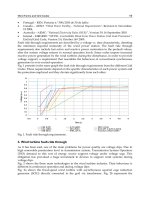
Figure 4.25
Printed circuit board inspection in electronics industry offers many
opportunities for detection of reject conditions before adding value
(courtesy of Teradyne/Control Automation).
Page 64
Similarly, where rejects are not preventable, separating scrap into that which can be reclaimed from that which cannot
is possible with machine vision. In the case of thick-film circuits, for example, the detection of the reject before firing
permits the reuse of the substrate. In the case of machined parts, parts that have dimensions that exceed the maximum
tolerance limit can generally be reworked, while those that exceed the minimum tolerances cannot. Machine vision
systems designed to make measurements on parts can be used to make the distinction, both on-line, as with the
previously mentioned laser gage types, and off-line, with television optical comparator analogs.
Real-time machine vision techniques can flag conditions and indicate the need for corrective action before a process
goes out of specification or at the very least after only a few rejects are experienced. Significant reductions in scrap and
rework costs can be achieved from the consistency of flexible automation such as machine vision (Figure 4.26).
Figure 4.26
Inex Vision Systems/BWI monitors positioning of
labels at rate of 1200 per minute.
Page 65
Figure 4.27
Early RVSI/Automatic vision system for weld seam
guidance to relax requirements of fixturing.
Clearly, machine vision has value although the tangible costs of scrap and rework are often hidden in manufacturing
overheads, thus making it difficult to expose the true cost associated with producing a bad product; for example, a
percentage of work-in-process inventory might be held pending scrap or rework decisions. Rework, similar to
inventory, is subject to shrinkage and to annual carrying costs. Unfortunately, it is difficult to quantify the savings that
result from making the product right the first time.
Another area to investigate that represents an opportunity for machine vision is one where expensive hard tooling is
required to hold a part for an operation (Figure 4.27). This may be avoidable totally or is at least a cheaper flexible
fixturing substituted if a machine vision system is used. In this case the system can
Page 66
provide location analysis, that is, so-called software fixturing. A key to this requirement is where setup time is lengthy
and the amount of time a part is actually being operated on is very small relative to the total cycle time associated with
an operation. Significantly, machine vision may offer increased flexibility, especially in assembly operations, that is,
flexibility to produce a wider variety of parts with shorter lead times, better response times to changes in designs, and
so on.
Another area for the use of machine vision is where a high incidence of equipment breakdown (Figure 4.28) is
experienced because of such problems as over- and under-size or misshapened and/or warped parts or misoriented
parts. A machine vision system upstream of the feeder mechanism can reduce or even eliminate downtime.
A situation that definitely warrants a machine vision system is one that involves the inventory of parts because
inspection may result in the rejection of a complete batch based on statistical sampling techniques. A 100% inspection
assures every part is good so ''just-in-time" inventory can be a by-product, with a corresponding reduction in the
material handling and damage experienced by handling. Similarly, machine vision opportunities exist where inspection
is a production bottleneck.
Figure 4.28
Early Opcon system verifies that label is properly positioned. Labels applied
inadvertently to area where flash exists gum up blades of deflashing unit,
resulting in equipment downtime.
Page 67
As with the justification for robots, one can look for applications related to unhealthy or hazardous environments. The
Occupational Safety and Health Administration (OSHA) has expressed concerns about the operator's well being: the
noise level is too high, the temperature is too hot, the products are too heavy, and so on. It may be that the environment
includes contaminants (metal dust or vapors) that can be injurious to a person. The converse may also be a
justification. People may bring contaminants into the environment that can damage the product, for example, dust,
causing damage to polished surfaces.
Where operation experiences errors due to operator judgment, fatigue, inattentiveness, or oversight brought about
because of the dullness of the job, machine vision opportunities exist (Figures 4.29, 4.30, 4.31 and 4.32). Certainly,
when an operation is experiencing a capital expansion mode, machine vision should be considered in lieu of
alternative, less effective, more costly methods. Where automation is contemplated as a substitute for people, it should
be understood that as people are removed, so are their senses, especially sight. When contemplating automation, an
analysis is necessary to assure that loss of sight will not affect the production process.
Figure 4.29
ORS Automation system inspects magnetic and signature strips of
credit cards for blemishes at rate of 400 per minute.
Page 68
Figure 4.30
Early system from Vanzetti Vision Systems performs "stranger elimination"
function to guarantee all capsules are right ones based on color at rates
up to 3600 per minute.
Table 4.7 summarizes how to identify potential applications for machine vision. Unquestionably, any operation can
identify opportunities for machine vision by performing an introspective examination of its operations. Table 4.8
summarizes the benefits that can accrue; these benefits can be the basis for justifying the purchase of machine vision.
The adoption of this technology, with the result of the objective 100% inspection of products, will cut costs, improve
quality, reduce warranty repairs, reduce liability claims, and improve consumer satisfaction - all components in an
improved profit picture.
Table 4.7 Identifying Applications
1. Lowest value added
2. Process control
3. Separate scrap that can be reworked
4. Avoid expensive hard tooling
5. Avoid equipment breakdown
6. Avoid excess inventory
7. Hazardous environment
8. Operator limitations essential
Page 69
Figure 4.31
Vision system from Systronic performs on-line inspection of diapers
to verify presence of all features.
Page 70
Figure 4.32
Vision system from Avalon Imaging verifying empty state of plastic injection
molding.
Page 71
Table 4.8 Machine Vision Benefits and Justification Summary
Economic Motivations
To reduce costs of goods manufactured by:
(a) Detecting reject state at point of lowest value added
(b) Automating to reduce work-in-process inventory
(c) Saving on tooling and fixturing costs
(d) Being able to separate scrap than can be reclaimed from that which cannot
(e) Providing early warning to detect incipient reject state to reduce scrap
(f) Reducing scrap and reworking inventory costs
(g) Reducing in warranty repairs, both in the field and returned goods
(h) Reducing service parts distribution costs
(i) Reducing liability costs
(j) Reducing liability insurance
(k) Improving production yield
(l) Reducing direct and indirect labor and burden rate
(m) Increasing equipment utilization
(n) Reducing setup time
(o) Reducing material handling cost and damage
(p) Reducing inventory
(q) Reducing paper
(r) Eliminating schedule upsets
Quality Motivations
To improve quality by:
(a) Conducting 100% inspection versus sample inspection
(b) Improving effectiveness of quality check to improve goods shipped and thereby improving customer
satisfaction
(c) Providing predictability of quality
People Motivations
(a) Satisfy OSHA
(b) Remove from hazardous, unhealthy environment
(c) Avoid contaminants in clean room
(d) Avoid strenuous task
(e) Avoid labor turnover and training costs
(f) Avoid need to hire for seasonal work
(g) Eliminate monotonous and repetitive job
(h) Expedite inspection task that is production bottleneck
(i) Reduce need for skilled people
(j) Avoid errors due to operator judgment, operator fatigue, operator inattentiveness, and operator oversight
(k) Improve skill levels of workers
Miscellaneous Motivations
(a)
(b)
(c)
(d)
(e)
(f)
(g)
Substitute capital for labor in expansion mode
Automate record keeping and capture statistics quicker
Feedback signals based on trend analysis to control manufacturing process
Function as "eyes" for automation
Enhance reputation as quality leader
Accelerate response to design changes
Get new technology into business
Page 72
References
Birnbaum, J., "Toward the Domestication of Microelectronics," Computer, November 1985.
Duncan, L. S., and Bowen, G. L., "Boosting Product Quality for Profit Improvement, "Manufacturing Engineering,
Society of Mechanical Engineers, April 1984.
Gevarter, W. B., "Machine Vision: A Report on the State of the Art," Computers in Mechanical Engineering, April
1983.
Kanade, T., "Visual Sensing and Interpretation: The Image Understanding Point of View," Computers in Mechanical
Engineering, April 1983.
Lerner, E. J., "Computer Vision Research Looks to the Brain," High Technology, May 1980.
Lowe, D. G., "Perceptual Organization and Visual Recognition," National Technical Instrumentation Service
Document AD A-150826.
Page 73
5—
Machine Vision:
Introductory Concepts
Machine vision all begin with an image - a picture. In many ways the issues associated with a quality image in
machine vision are similar to the issues associated with obtaining a quality image in a photograph. In the first place,
quality lighting is required in order to obtain a bright enough reflected image of the object. Lighting should be
uniformly distributed over the object. Non-uniform lighting will affect the distribution of brightness values that will be
picked up by the television camera.
As is the case in photography, lighting tricks can be used in order to exaggerate certain conditions in the scene being
viewed. For example, it is possible that shadows can, in effect, include high contrast information that can be used to
make a decision about the scene being viewed.
The types of lamps that are used to provide illumination may also influence the quality of the image. For example,
fluorescent lamps have a higher blue spectral output than incandescent lamps. While the blue spectral output is more
consistent with the spectral sensitivity of the eye, higher infrared output is typically more compatible with the spectral
sensitivity of solid state sensors that are used in machine vision.
It has been found that the sensitivity of human inspectors can be enhanced as a consequence of using softer lighting or
fluorescent lamps with gases that provide more red spectral output; so too it may also be the case in machine vision.
That is, that the lamp's spectral output may influence the contrast associated with
Page 74
the specific feature one is attempting to analyze. This has been demonstrated in the case of many organic products.
As in photography, machine vision uses a lens to capture a picture of the object and focus it onto a sensor plane. The
quality of the lens will influence the quality of the image. Distortions and aberrations could effect the size of features
in image space. Vignetting in a lens can affect the distribution of light across the image plane. Magnification of the
lens has to be appropriate for the application. As much as possible the image of the object should fill the image plane
of the sensor.
Allowances have to be made for any registration errors associated with the position of the object and the repeatability
of that positioning. The focal length and aperture have to be optimized in order to handle the depth of field associated
with the object.
The imaging sensor that is used in the machine vision system will basically dictate the limit of discrimination of detail
that will be experienced with the system. Imaging sensors have a finite number of discrete detectors and this number
limits the number of spatial data elements that can be processed or into which the image will be dissected. In a typical
television-based machine vision system today the number of spatial data points is on the order of 400 to 500 horizontal
× 400 to 500 vertical.
Basically, what this means basically is that the smallest piece of information that can be discriminated is going to be a
function of the field of view. Just like in photography, one can use panoramic optics to take a view of a mountain
range, and although a family might be in the picture in the foothills of the mountains, it is unlikely that you would be
able to discriminate the family in the picture. On the other hand, using a different lens and moving closer to the family,
one would be able to capture the facial expressions of each member, but the resulting picture would not include the
peaks of the mountains.
So, for example, given that an application requires a one-inch field of view, and a sensor with the equivalent of 500
spatial data points is used, one would have a spatial data point that would be approximately .002 inches on the side.
Significantly, the ability of machine vision today to discriminate details in a scene is generally better than the size of a
spatial data point.
In a manner basically analogous to how an eye can see stars in a night sky because of the contrast associated with the
star light, so too in machine vision techniques exist which allow systems to be able to discriminate details smaller than
a spatial data element. Again, contrast is critical. The claims for subpixel sensitivity vary from vendor to vendor and
depend very much on their execution and the application.
In all machine vision systems up until this point in our discussion, the information or the image has been in an analog
format. For a computer to operate on the picture the analog image must be digitized. This operation basically consists
of sampling at discrete locations along the analog signal that corresponds to a plot of time vs. brightness, and
quantizing the brightness at that sample point.
Page 75
The actual brightness value is dependent on: the lighting, the reflective property of the object, conditions in the
atmosphere between the lighting and the object and between the object and the camera, and the specific detector
sensitivity in the imaging sensor. Most vision systems today characterize the brightness into a value of between 0 and
255. The brightness so characterized is generally referred to as a shade of gray.
For the most part today, machine vision systems are monochromatic. Consequently, the color may also be a factor in
the brightness value. That is, it is possible to have a shade of red and a shade of green (and so on) all of which would
have the same brightness value. In many cases where color issues are a concern, filters are used in order to eliminate
all colors that are not of interest to the particular application. In this way the gray shades are an indicator of the
saturation level associated with a specific color. Color cameras can also be used to acquire the data and segmentation
based on the specific color enabled.
At last we have a picture that has been prepared for a computer. In most machine vision systems today, the digitized
image is stored in memory that is separated from the computer memory. This dedicated memory is referred to as a
frame store - where frame is synonymous with the term used in television to describe a single picture. In some cases
the dedicated hardware that includes the frame store also includes the analog-to-digital converter as well as other
electronics to permit one to view images after processing steps have been conducted on the image to view the effects
of these processing procedures.
Now the computer can operate on the image. The operation of the computer on the image is generally referred to as
image processing. In addition to operating on the image, the computer is also used to analyze the image and make a
decision on the basis of the analyzed image and perform an operation accordingly. What is typically referred to as the
vision engine part of the machine vision system is the combination of image processing, analysis and decision-making
techniques that are embodied in the computer.
A good analogy can be made to a toolbox. Virtually all machine vision systems today include certain fundamental
tools, much like a hammer, screwdriver or pliers. Beyond these, different suppliers have developed additional tools,
more often than not driven by a specific class of applications. Consequently the description frequently given for
machine vision as being an "idiot savant" is quite apropos. That is, most of the platforms are brilliant on one set of
applications but "idiots" or truly not the optimal for other applications.
It is important, therefore, to select the vision platform or toolbox with the most appropriate tools for an application.
Significantly, no machine vision systems exist today that come anywhere near simulating the comprehensive image
understanding capabilities that people have. It is noted that for many applications many different tools will actually do
the job and in many cases without sacrificing performance. On the other hand, in some cases while the tools appear to
do the
Page 76
job, performance might be marginal, in a manner analogous to when we attempt to use a flat head screwdriver in order
to turn a screw with a Phillips head.
Image processing is generally performed on most images for basically two reasons: to improve or enhance the image
and, therefore, make the decision associated with the image more reliable, and to segment the image or to separate the
features of importance from those that are unimportant. Enhancement might be performed, for example, to correct for
the non-uniformity in sensitivity from photo site to photo site in the imaging sensor, correct for distortion, correct for
non-uniformity of illumination, to enhance the contrast in the scene, correct for perspective, etc.
These enhancement steps could be as simple as adding or subtracting a specific value to each shade of gray or can
involve a variety of logical operations on the picture. There are many such routines. One routine that is commonly
found as a tool for image processing in most vision platforms today is a histogram routine. This involves developing a
frequency distribution associated with the number of times a given gray shade is determined.
One use of histograms is to improve contrast. This involves mathematically redistributing the histogram so that pixels
are assigned to gray shades covering 0 to 255, for example. In an image with this type of contrast enhancement, it
could be easier to establish boundaries or easier to establish a specific gray shade level or threshold to use to binarize
the image. Binarizing an image, or segmenting an image based on a threshold above which all pixels are turned on and
below which all pixels are turned off, is a conventional segmentation tool included in most vision platforms and can be
effective where high contrast exists.
Where contrast in a scene is not substantial, segmentation based on edges may be more appropriate. Edges can be
characterized as locations where gradients or gray shade changes take place. Both the gradient as well as the direction
of change can be used as properties to characterize an edge. Significantly, edges can be caused by shadows as well as
reflectance changes on the surface in addition to the boundaries of the object itself. Artifacts in the image may also
contribute to edges. For example, unwanted porosity may also be characterized by increased edges.
There are many different ways edges are characterized. One of the simplest is just using the fact that there are sharp
gray scale changes at an edge. Significantly, however, edges in fact appear across several neighboring pixels and what
one has is in fact a profile of an edge across the pixels. Because of this, there are ways to mathematically discriminate
the physical position of an edge to a value less than the size of the pixel. Again, there are many ways that these
subpixel calculations have been made and the results are very application dependent. Consequently, although claims
are made of one part in ten or better subpixelling capability, it is important to understand that the properties of a given
application can reduce the effectiveness of subpixelling techniques.
Page 77
Having performed image-processing routines to enhance and segment an image, the computer is now used to analyze
the image. The specific analysis conducted is again going to be very application-dependent. In the case of a robot
guidance application, for example, a geometric analysis would typically be conducted on the segmented image.
Looking at the thresholded segmented image or edge segmented image one would be able to calculate the centroid
property and furnish this as a coordinate in space for the robot to pick up an object, for example.
In the case of using vision systems to perform inspections of one type or another, there are literally hundreds of
different types of analysis techniques that have emerged. The number of pixels associated with the binarized or
thresholded picture, for example, could be counted. This could be a relatively simple measure of the completeness of
an object. The number of transitions or times that one goes from black to white can be counted. The distance between
transitions can be counted and can serve as a measurement between boundaries of an object. The number of pixels that
are associated with an edge can be counted. Vectors associated with the direction of the gradient at an edge can be used
as the analysis features. A model based on the edges can be derived where the edges can be characterized as vectors of
a certain length and angle. Geometric features can be extracted from the enhanced image and used as the basis of
decisions.
These same techniques can be used in conjunction with pattern recognition applications. In each case, one or more of
the above-mentioned features extracted from the image can define a pattern. For example, maybe a combination of the
transition counts and edge pixels would be sufficient to make a judgement about patterns where that combination is
sufficient to distinguish between the patterns. Another approach might be to use geometric properties to distinguish
patterns. These might include length and width ratios, perimeter, etc.
The computer, having reduced the image to a set of features used as the basis of analysis, would typically then use a
deterministic or probabilistic approach to analyze the features. A probabilistic approach is one that basically suggests
that given a certain property associated with a feature, there is a high probability that the object is in fact good. So, for
example, using the total number of pixels as an indication of the completeness of an object one would be able to
suggest that if the total number of pixels exceeded, say, 10,000 there is a high probability that the object is complete. If
less than 10,000 the object should be rejected because it would be characterized as incomplete. Some refer to this as
goodness-of-fit criteria. It is also possible to set a boundary around these criteria. That is, it should fall between 10,000
and 10,500. An indication of a pixel count greater than 10,500 could be an indication, for example, of excess flashing.
A deterministic approach is one that will use physical feature properties as the criteria. For example, the distance
between two boundaries has to be one inch +/- .005''. The perimeter of the object must fall between 12 inches
+/- .020". The pattern must match the following criteria in order to be considered a match:
Page 78
length/width ratio of a certain value, perimeter of a certain value, centroid of a given calculated value, etc.
In a deterministic mode each of the features can be associated with a vector in decision space. In a pattern recognition
application, the combined feature vector or the shortest distance to the known feature set for each of the patterns is the
one that would be selected. This type of evaluation is referred to as decision theoretic. Another type of analysis is one
based on syntactic techniques. In these cases, primitives associated with pieces of the image are extracted and the
relationship between them is compared to a known database associated with the image.
In other words, the primitives and their relationship to each other have to abide to a set of rules. Using syntactic
techniques one may be able to infer certain primitives and their position knowing something about other primitives in
the image and their position with respect to each other. This could be a technique to handle parts that might be
overlapping and still be able to make certain decisions associated with those parts even though one can not see them
entirely.
As you can see, there are many vision tools that are available and the specific tools that one requires are application-
dependent.
5.1—
Who Is Using Machine Vision
Today one can find machine-vision-type technology in virtually every manufacturing industry. The largest adopter by
far is the electronics industry. In microelectronics, machine vision techniques are used to automatically perform
inspections throughout the integrated circuit manufacturing process: photomask fabrication, post die slicing inspection,
pre-cap inspection and final package inspection for mark integrity.
Throughout the manufacturing process, machine vision is also used to provide feedback for position correction in
conjunction with a variety of manufacturing processes such as die slicing and bonding and wire bonding. In the
macroelectronic industry machine vision is being used to inspect printed circuit boards for conductor width spacing,
populated printed circuit boards for completeness, post solder inspection for solder integrity.
As in microelectronics, it is also being used to perform positional feedback in conjunction with component placement.
It has become an integral part of the manufacturing process associated with the placement of chip carriers with
relatively high-density pin counts.
In industries that produce products on a continuous web, such as the paper, plastic, and textile industries, machine
vision techniques are being used to perform an inspection of the integrity of the product being produced. Where
coatings are applied to such products, machine vision is also being used to guarantee the coverage and quality of
coverage. In the printing industry, one finds machine vision being used in conjunction with registration.
Page 79
The food industry finds machine vision being used in the process end to inspect products for sorting purposes, that is,
sorting out defective conditions or misshapen product or undersize/oversize product, etc. At the packaging end, it is
being used to verify the size and shape of contents, such as candy bars and cookies, to make sure they will fit in their
respective packages.
Throughout the consumer manufacturing industries one will find machine vision in various applications. These include
label verification, that is, verifying the position, quality and correctness of the label. In the pharmaceutical industry one
finds it being used to perform character verification, that is, verifying the correctness as well as the integrity of the
character sets corresponding to date and lot code.
The automotive industry finds itself using machine vision for many applications. These include looking at the
flushness and fit of sheet metal assemblies, including the final car assembly; looking at paint qualities, such as gloss;
inspecting for flaws on sheet metal stampings; verifying the completeness of a variety of assemblies from ball bearings
to transmissions; etc.; used in conjunction with robots to provide visual feedback for: sealant applications, windshield
insertion applications, robotic hydropiercing operations, robotic seam tracking operations, etc.
Virtually every industry has seen the adoption of machine vision in some way or another. The toothbrush industry, for
example, has vision systems that are used to verify the integrity of the toothbrush. The plastics industry looks at empty
mold cavities to make sure that they are empty before filling them again. The container industry is using machine
vision techniques widely. In metal cans they look at the quality of the can ends for cosmetic flaws, presence of
compound, score depth on converted ends, etc. The can itself is examined to inspect it for defective conditions
internally.
The glass container industry uses machine vision widely to inspect for sidewall defects, mouth defects and empty
bottle states as well as dimensions and shapes. In these cases, vision techniques have proven to be able to handle 1800
to 2000 objects per minute.
5.2—
Deploying Machine Vision
How do I know what machine vision techniques are most suitable for my application? A studied approach is usually
required unless the application is one that has a system that has been widely deployed throughout an industry. In that
case the pioneering work has already been done. Adaptation to one's own situation, while not trivial, may have little
risk. To find out if your application has been solved, ask around. Today, most machine vision companies are quite
helpful. If they do not offer the specific solution, but know of any other company that does, they will generally respond
with candor and advise accordingly. Consultants may also be able to identify sources of specific solutions.
Having identified those sources they should be contacted to identify their referenceable accounts and these in turn
should be contacted to determine: why
Page 80
they were selected, what has been the experience, service, etc., and would they purchase the same product? This should
help to narrow down the number of companies to be solicited for the project. In this case, the ultimate selection will no
doubt be largely based on price, though policies such as training, warranty, service, spare parts, etc., should also be
considered, as they will impact the life cycle cost.
What do you do if you find your application is not a proliferation of someone else's success? In this case a detailed
application description and functional specification should be prepared. This means really getting to know the
application - what are all the exceptions and variables? The most critical ones are position and appearance. These must
be understood and described comprehensively.
What are the specific requirements of the application? Will the system first have to find the object - even minor
translation due to vibration can be a problem for some machine vision executions. In addition to translation, will the
part be presented in different rotations? Are different colors, shades, specular properties, finishes, etc. anticipated?
Does the application require recognition? Is it gaging? What are the part tolerances? What percent of the tolerance
band would it be acceptable to discriminate? If flaw detection, what size flaw is a flaw? Is the flaw characterized by
reflectance change, by geometric change, etc.?
Having prepared the spec, at least a preliminary acceptance test for system buy-off should be prepared and solicitations
should be forwarded to potential suppliers. How do you identify those suppliers? A telephone survey of the 150 or so
companies is one approach. Again, use of a consultant can greatly accelerate the search. In any event, the leading
question should be whether or not they have successfully delivered systems that address similar requirements.
Since we have already established that the application does not represent the proliferation of an existing system
solution, the best one can expect is to find a number of companies that have been successful in delivering systems that
address needs similar to yours and seemed to have been able to handle similar complexities. So, for example, if the
application is flaw detection - are the type and size flaws similar? Are the part, size and geometric complexity and
material similar? Is part positioning similar, etc.?
This survey should narrow the number of companies to be solicited to four to six. The solicitation package should
demand a certain proposal response. It is important to get a response that reflects that the application has truly been
thought about. It is not sufficient to get a quotation and cover letter that basically says "trust me" and "when I get the
order I will think about how I'm going to handle it." The proposal should give system details. What lighting will be
used and why was that arrangement selected? How about the camera properties, have they been thought through? How
about timing, resolution, sampling considerations, and so forth?
Most importantly, does the proposal reflect an understanding of how the properties of the vision platform will be
applied and can it defend that those prop-
Page 81
erties are appropriate for the application? How will location analysis be handled? What image processing routines will
be enabled specifically to address the application? A litany of the image processing routines inherent in the platform is
not the issue. Rather, what preprocessing is being recommended, if any? What analysis routines, etc.? Along with this,
an estimate should be prepared of the timing associated with the execution from snapping a picture through to signal
availability reflecting the results of a decision. This should be consistent with your throughput requirements.
When a vendor has thought through the application this way and conducted a rather comprehensive analysis, he is in a
good position to provide both a schedule of project development tasks and a good estimate of the project cost. An
excellent paper that describes this systematic approach as applied to a "Frobus Assembly" was written by Dr. Joseph
Wilder and can be found in SPIE Volume 849 "Automated Inspection and High Speed Vision Architectures."
By insisting on this type analysis in the proposal, both vendor and buyer should avoid surprises. Among other things, it
will give the buyer a sense that the application is understood. Those proposals responsive in this manner should be
further evaluated using a systematic procedure such as Kepner Tregoe decision-making techniques. These involve
establishing criteria to use as the basis of the evaluation, applying a weighting factor to the criterion and then
evaluating each of the responses against each weighted criterion to come up with a value.
This value represents a measure of how a company satisfies the criterion along with the relative importance of that
criterion to the project. In some cases, the score given should be 0 if the approach fails to satisfy one of the absolute
requirements of the application. A good paper describing the application of these techniques to evaluating machine
vision proposals was written by Ed Abbott and delivered at the SME sponsored Vision 85 Conference, March 25–28,
1985.
Having made a decision on a vendor, justifying the project may be the next issue. Significantly, justification based
solely on labor displacement is unlikely to satisfy the ROI requirements. Quantifying additional savings is more
difficult but in reality may yield an even greater impact than labor savings. Product returns and warranty cost should be
evaluated to assess how much they will be reduced by the machine vision system. The cost of rework should be a
matter of record. In addition, however, a value can be calculated for the space associated with rework inventory as well
as the rework inventory itself. The cost of rejects and related material costs, the cost of waste disposal associated with
rejects, and the cost of freight costs on returns are all very tangible quantifiable costs.
There are other savings, through less tangible, which should be estimated and quantified. These include items such as:
1. The cost of overruns to compensate for yield.
2. The avoidance of inspection bottlenecks and impacton inventory income and inventory turnover.
3. The elimination of adding value to scrap conditions.
Page 82
4. The potential for increased machine uptime and productivity accordingly.
5. The elimination of schedule upsets due to the production of items that require rework.
Another observation is that when considering the savings due to labor displacement, it is important to include all the
savings. These include:
1. Recruiting
2. Training
3. Scrap rework created while learning a new job
4. Average workers compensation paid for injuries
5. Average educational grant per employee
6. Personnel/payroll department costs per employee
Overall the deployment of machine vision will result in improved and predictable quality. This in turn will yield
improved customer satisfaction and an opportunity to increase market share - the biggest payback of all.
Page 83
6—
Image Acquisition
6.1—
Introductory Concepts
The application of machine vision technology involves dealing with many visual variables. In most cases one must be
forgiving of some variables and sensitive to others, the system must detect. Even simple applications have to contend
with variables that a person performing the same task can easily dismiss. Label presence and/or absence detection is
often cited as a machine vision application. One variable a system must be able to contend with is hue saturation. For
example, a label may be perfectly acceptable as long as its "color" is yellow, from pastel to virtually orange. A person
can easily accept this range and still detect a missing or skewed label. A machine vision system may be tricked into
thinking the label is missing when actually the acceptable hue saturation change is what was experienced.
Lighting and optics in many applications can be optimized to enhance the contrast associated with the variable for
which a system is purchased or, conversely, can assist in diminishing the influence of the variable on the data required
to make a reliable "vision/decision."
In a given machine vision installation, dedicated lighting is recommended. However, secondary sources of illumination
may come from ambient lighting and the reflection of the primary source of light off of other equipment or even a floor
after polishing! The net result is a complex pattern of light in which uniformity is
Page 84
a compromise. This can affect the nature of shadows and shading on the surface, which can affect the interpretation of
the object.
Gray Levels encoded by a machine vision system are physical measurements are a function of illumination, viewpoint,
surface reflectance, and orientation. In general, variations in illumination, surface reflectance, and surface orientation
give rise to shaded images as seen from a viewpoint; surface reflectance, and surface orientation give rise to shaded
images as seen from a given viewpoint.
The reflectivity property of an object is determined by such surface characteristics as texture or color. An object of
uniform color and smoothness reflects light uniformly from all points on its surface. Real objects do not behave this
way, experiencing varying surface properties, and consequently, variations in brightness are observed in images.
Human perception of brightness or the color of a part of an image is strongly influenced by the brightness or color of
the neighboring parts. The relative constancy of the perceived lightness and color of a surface under different
illumination conditions also affect human perception. A gray piece of paper taken from a poorly lit room into the
bright outside sunshine still appears gray, even though the amount of light reflected is several orders of magnitude
greater than from a white piece of paper indoors. Similarly, a surface of a certain color generally retains its perceived
hue even though the color of illumination changes.
A sensor, whose response is proportional to the average light intensity in a small neighborhood, makes local
measurement of the brightness of a small area of an image, while to the eye the perceived brightness is dependent on
the intensities of the surrounding pixels. The human perception of color involves differentiation based on three
independent properties: intensity, hue, and saturation (Figure 6. 1).
Figure 6.1
Three dimensional color system
(courtesy of Hunter Lab).
Page 85
Hue corresponds to color (blue, red, etc.), intensity is the lightness value, and saturation is the distance from lightness
per hue. For a monochromatic source of light, our perception of hue is directly dependent on wavelength. However, in
normal environments, objects of a certain hue, say, red, do not reflect just the light of a single wavelength but rather a
broad spectrum that has a distribution different from that of the white light. Different hues are also obtained by mixing
colors, for example, green from blue and yellow, even though the mixed light may contain no green wavelength.
Colors are synthesized from a mixture of three primary colors. Commonly used primary colors are red, green, and
blue. These need not be monochromatic but may have a wide spectrum distribution of light intensity. Television
cameras, as with the eye, do not measure the perceived attributes of intensity, hue, and saturation directly. Instead, the
measured attributes correspond to the intensity of the three primary-color components in the viewed surface.
Surface orientation stemming from the geometry of the surface of an object can result in light intensity variations. A
surface perpendicular to the light appears brighter than if aligned at some other angle. Complex geometric shapes will
result in complex variations in surface brightness in the image. Significantly, in some applications the data of value
about the scene can be inferred from shadows.
The integration of the four variables (illumination, viewpoint, surface reflectance, and surface orientation) along with
the nonobject or system factors enumerated in Chapter 1 results in the encoded value at a pixel site. The resulting
distribution of light intensities forms an image, a two-dimensional representation of a typically three-dimensional
scene.
6.1.1—
Application Features
Features that characterize an image of a scene include position (location and orientation in space), geometry or shape,
and light intensity distribution. The location of an object refers to its coordinates in space. Orientation refers to the
direction of a specific axis of the object. The geometric features of an object can be used to distinguish it from other
objects or to verify its dimensional properties. The light intensity distribution of an object may also be a means of
recognizing or distinguishing one object from another. It can also be used to tell something about the surface or
cosmetic properties of an object as well as to verify that certain conditions are satisfied.
As indicated, the requirements addressed by machine vision technology are varied. While the front end always consists
in some form of image acquisition to be further processed and analyzed, the intended outcome of the analysis can be
the analysis of one or several quite different attributes of the object based on the requirements of the application:
1. The simple presence or absence of an object, or a part of an assembly.
Page 86
2. The general shape and/or profile of an object or one of its parts, and its distribution in class groups.
3. The particular location or orientation of a part in an assembly.
4. The determination of the color and/or shade of an object and/or of some of its parts.
5. The determination of surface conditions of an object, such as finish, polish, texture, dust. These are usually
unwanted attributes in unpredictable and random locations.
6. The optical density at specified colors, or integrated color bands (for example, tinted eyeglasses).
7. The determination of a dimensional property, such as length, thickness, depth, azimuth, angle, depth of thread, and
their distribution in class groups.
8. Combinations of 1–7.
9. The use of motion analysis to obtain 3-D shape information as well as direction information (e.g., for an autonomous
land vehicle).
10. Object recognition as distinct from checking the simple presence or absence of an object (e.g., in distinguishing
between a square and a circle).
Some of these parameters relate to the cosmetic appearance of a product. The need for machine vision inspection arises
in those cases from the psychological expectation that the good appearance of a product will result in its better
acceptance in the marketplace.
Other parameters relate to the integrity of a product. An engine block, for example, should have its crankcase fully
bolted, before being placed in the chassis. A pharmaceutical blister package must contain a specified number of tablets;
they should be completely formed and of the right color. Still other parameters relate to the reproducibility or
constancy of tolerances. The human eye, though sensitive and discriminating, cannot make quantitative judgements
that are reproducible from event to event, even less from individual to individual observer. The color of a fabric, for
example, could slowly change from hour to hour in one direction, without a human inspector perceiving it. A closure
must fit the mating part of a container within specified tolerances. A slight change in the bevel of a hypodermic needle
would pass unnoticed by the inspector.
Still other conditions may prevail when, because of their small size, color, physical inaccessibility, or other limitation,
some of the "visual" parameters cannot be seen by the unaided human eye, but only by an appropriate sensor.
6.2—
Light and Lighting
Whether it involves human or machine hardware, visual data acquisition proceeds essentially in three steps. In human
vision, for example, the object should be properly lighted so as to make it "visible" to the human eye; second, the
human eye, itself a lensing system, is needed to image the object on the target of the sensor, or the retina; finally, the
retina should somehow "read" and a signal to be further processed conveyed to the brain by the optical nerve.
Page 87
Similarly in machine vision, the first step is to properly light the object to render it detectable by the sensor. The
second step consists of imaging the object on the target of the sensor.
6.2.1—
Contrast and Resolution
Image-capturing typically involves acquiring the two dimensional projections of a three-dimensional object. The two
most important qualities of the image are contrast and resolution. That is, the attributes of the image that will become
the basis of an action or decision must be distinguishable and resolvable (or measurable).
Contrast is the range of differences between the light and dark portions of an image. Normally, contrast is measured
between the feature(s) containing the needed information and the immediate objects surrounding these features
(referred to as background).
The ideal image has ultimate contrast, with the desired information having intensity values of absolute white, and
background (everything else) intensity values of absolute black.
Resolution (or the ability to see two closely spaced objects) is a distance measurement associated with the smallest
detectable object. The resolution required depends on the task of the machine vision system. If a system is needed to
locate a part in X and Y to within one inch, the system resolution needs to be less than one inch. Unlike contrast,
infinite resolution is not always desired. An example is measuring the gap of a spark plug. Too much resolution would
result in an image of the electrode surface appearing mountainous, uneven and pitted, not smooth and flat.
Lighting and optics can have an effect on both contrast and resolution in many applications. Lighting and optics can be
optimized to enhance the delectability associated with the variables for which a system is purchased, or conversely, can
assist to diminish the influence of the variable on the data required to make a reliable ''vision decision."
6.2.2—
Lighting
In a given machine vision installation, dedicated lighting is strongly recommended because secondary sources of
illumination may come from ambient lighting and the reflection of the primary source of light off other equipment,
objects, or the floor and windows. The net result is a complex pattern of light in which uniformity is a compromise.
This can affect the nature of shadows and shading on the surface which can affect the recognition of the object.
The objectives of lighting are:
1. Optimize the contrast (gray scale difference) associated with the condition one seeks to detect versus the normal
state.
2. Normalize any variances due to ambient conditions.
3. Simplify image processing and, therefore, computing power required.
Page 88
Lighting in a machine vision application can make the difference between a successful and unsuccessful application.
Illumination can either enhance features to be detected or obscure them. Poorly designed lighting can produce glare
which may saturate the camera, create shadows which can include the data to be detected or obscure them, and
generate low contrast or nonuniformity making the inspection difficult. Sufficient illumination is also required because
sensors have designated minimum levels - the minimum amount of light required to produce a voltage video signal.
Lighting considerations in a given application include:
1. The type of light. Incandescent, fluorescent, quartz halogen, sodium, lasers, light emitting diodes, etc., all emit
different wavelengths (colors) of light. The type used should illuminate the part's surface and also be measurable by the
sensor type used.
2. The lighting technique is the geometric setup between the part, any lights and the sensor. This depends on what
information is desired; maybe a silhouette is needed, or the bottom of a deep bore needs to be illuminated. Different
lighting techniques would be used for each case.
3. The control of the illumination may include the passive blocking of light with covers or shades.
4. Geometry of propagation. There are three types of sources: point, diffuse and collimated. A single point of light will
create shadows that accent edges. If shadows will block areas where information is needed, a diffuse light source will
eliminate shadows.
5. At times the shape of the light "beam" can be used as a method to gain information from the scene. Shapes can
include points, lines, crosses, gratings, etc. These are called "structured lighting techniques."
The specific lighting technique used for a given application depends on:
1. The object's geometric properties (specularity, texture, etc.)
2. The object's color
3. The background
4. The data to be extracted from the object (based on the application requirement).
As an introductory comment, it is noted that quite contrary to common thinking, the human eye or a sensor does not
really "see" an object; rather they see the reaction of an object to incident light. This is the reason an object is seen
differently when illuminated by different types of light and is not seen at all in the absence of exciting light. Hence, it
is important to recall the properties of light that determine its interaction with objects.
6.2.3—
Light
Light is electromagnetic energy generated by random atomic processes, in turn caused by heat, collisional, or electrical
excitation. This energy statistically
Page 89
builds up to an oscillating electric field propagating in space as a traveling wave with a velocity of 3 × 10
10
cm/sec in a
vacuum (Figure 6.2).
Figure 6.2
Light as traveling wave.
6.2.3.1—
Wavelength
The frequency of a field or its reciprocal, the wavenumber, or the wavelength, which is the wavenumber multiplied by
the velocity, covers an extremely wide range, extending from the gamma rays at the short end, of 10
-10
cm, to the
radiowaves at the very long end, of several kilometers (Figure 6.3). Wavelength determines whether and how much
light interacts with matter and how much of this interaction is detected by the human eye or by a sensor.
6.2.3.2—
Polarization
The wave generated by an elementary source, being transverse, is essentially polarized (Figure 6.2). Most practical
sources, however, are made up of many elementary sources that are all random. Hence, most practical sources have
polarization distributed uniformly within the 360 degrees of the wavefront.
6.2.3.3—
Geometry of Propagation
The direction of illumination or its propagation in space depends on the geometry of the integrated source. In that
respect, there are essentially three types of sources: point, diffuse, and collimated (Figure 6.4).
1. Point source essentially originates from a geometric or very small point - a spherical source with infinitesimal
diameter. Its propagation is uniform within the 4 Π solid angle. A point source illuminates an object from a single
direction and hence causes reflections and shadows. Shadows are sometimes desired and include the data upon which a
decision is based. Point sources of light cast very strong shadows. This is sometimes desired if the presence or absence
of shadow can reveal information about the presence or absence of depth. Point sources of light are also very good for
revealing surface defects.
Good point source illumination can be obtained from:
Incandescent spot lights (lights emitted by a hot object)
Page 90
Figure 6.3
Electromagnetic spectrum.
Page 91
Fiber optic sources, slightly overlapping, provide good uniform point source illumination. (This is the best choice, but
it is an intense light having a short lifetime and a high price tag.)
Unfrosted incandescent light bulbs (e.g., Tensor, or conventional room light bulbs).
2. Diffused light originates from an "extended source," consisting of many point sources distributed uniformly on a
plane in space. It is incident on an object from all directions, creates little or no reflection, and no shadows. Most
machine vision applications work best when illuminated with diffuse light. Good sources of diffuse lighting include:
Fluorescent ring lights
Long fluorescent bulbs with or without light diffusers
Fiber optic ring illuminators (very intense light)
Banks of light-emitting diodes
3. A collimated beam consists of a single unidirectional and generally quasi-parallel beam. It originates from a single
source optically located at an infinite distance. It creates reflection and sharp shadows.
6.2.4—
Practical Sources
Sources of light for machine vision vary from the common incandescent lamp to sophisticated lasers. One source of
light almost never used is ambient light. The vagaries of ambient light are typically beyond the capability of state-of-
the-art machine vision systems to handle.
6.2.4.1—
Incandescent Light Bulb
Light (and heat) is obtained from an incandescent tungsten metal filament heated to 2000–2500 K by passing an
electrical current. Its spectral response is that of the "black body" (as defined in physics text books), whose emitted
wavelength distribution depends on the temperature (Figure 6.5). At 2000 K, it peaks at 1500 nm and dies out at
around 200 nm. For certain vision applications, such as those requiring gray scale rendition, it may be best to regulate
the current to the bulb.
Figure 6.4
Three types of light sources: point, diffuse and collimated.
Page 92
Figure 6.5
Wavelength versus number of photons.