Grippers in Motion - the Fascination of Automated Handling Tasks - Wolf Part 7 doc
Bạn đang xem bản rút gọn của tài liệu. Xem và tải ngay bản đầy đủ của tài liệu tại đây (1.61 MB, 20 trang )
revolver gripper
CGJS
CGS
QCGJS
QCGS
one-purpose gripper 1
several OE
prismatic jaws
comb jaws
mold jaws
adjustable jaws
dual gripper
2
4 - 10
2 - oo
2 - oo
2 - oo
2 - oo
2 - 3
1 - 3
1 - 4
1 - 5
1 - 6
flexible gripper jaws
swivel grippers
multiple grippers
<< degree of flexibility
0 1 2 3 4 5 6 7 8 9 10 11 12 n
QCGS
quick-change gripper system QCGJS quick-change gripper jaw system
CGS change gripper system CGJS change gripper jaw system OE operating elements
workpiece variety >>
Getting To Grips With Handling Tasks
3
A revolver gripper consists of more than two grippers which are
able to work independently and is predominantly used for handling
several workpiece types. One workpiece type is distinguished
from another according to which gripper is able to cope with it. The
structure of the operating elements on a dual gripper or a revolver
gripper may be parallel, coniform or radial.
Small and medium-sized product lines demand gripping technology
to be even more flexible as the aim is always to cover the broadest
range of workpieces possible. Gripper fingers with a long stroke
meet this demand.
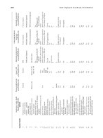
Figure 3.13 Flexible gripper systems coping with workpiece variety
parallel, coniform and
radial structure of
revolver grippers
122
iÛiÀÌiiÃÃ]ÊÜÀ«iViÊÛ>ÀiÌÞÊÃÊÊÌÃÊÜ>ÞÊÌÊ>À}iÊÃiÀiÃÊ
«À`ÕVÌÊ>ÃÊÜi°Ê>ÃÃÊ«À`ÕVÌÊÊÌÃÊÌÀÕiÊÃiÃiÊÃÊÞÊ
ÀiiÛ>ÌÊvÀÊÃ}iÊÜÀ«iViÃ]ÊV«iÌÃ]ÊÀÊÜiÊÃÞÃÌiðÊ
ÃÕiÀÊ}`Ã]Êi°Ê}°Ê>ÕÌLiÃ]Ê>ÀiÊVÀi>Ã}ÞÊ«À`ÕVi`Ê
>VVÀ`}ÊÌÊ`Û`Õ>ÊÀ`iÀ°ÊÜiÀÊÌÊÕLiÀÃÊ>}>ÊÀiµÕÀiÊ
ÀiÊ>`}ÊyiÝLÌÞ°Ê,LÌÃÊÊVL>ÌÊÜÌÊyiÝLiÊ}À«
«}ÊÌiV}ÞÊ>`ÊÃiÃÀÃÊ>ÀiÊÌiÊ>ÌiÃÌÊÃÌ>ÌiÊvÊi}iiÀ}°Ê
Ý«iÃiÃÊvÀÊÌiÊÀiëiVÌÛiÊ}ÌiVÊV«iÌÃÊÀÃiÊ>VVÀ`}Ê
ÌÊÌiÊ«iÀvÀ>ViÊÀiµÕÀi`°
}ÕÀiÊΰ£ÎÊiÝ«>ÃÊÛ>ÀÕÃÊ«ÌÃÊvÀÊ}À««iÀÊÃÞÃÌiÃÊV«}Ê
ÜÌÊÜÀ«iViÊÛ>ÀiÌÞ°Ê/iÊÃ}iÊ«ÕÀ«ÃiÊ}À««iÀÊ>ÃÊ}À««iÀÊ>ÜÃÊ
Ì>Ài`ÊÌÊÌiÊÜÀ«iViÊ>`ÊV>ÊLiÊiµÕ««i`ÊÜÌÊyiÝLiÊ}À««iÀÊ
w}iÀÃÊvÀÊ>``Ì>ÊyiÝLÌÞ°ÊÊ}À««iÀÊÃÞÃÌiÃÊ`i}ÀiiÊvÊyiÝ
LÌÞÊÃÊiÝ«ÀiÃÃi`ÊLÞÊÌiʵÕ>ÌÌÞÊvÊ`vviÀiÌÊÜÀ«iViÃÊÌÃÊ
}À««iÀÊÃÞÃÌiÊV>ÊV«iÊÜÌ°Ê/iÊwÀÃÌÊÃÌi«ÊÃÊÌÊÕÃiÊÃiÛiÀ>Ê
VÌ>VÌÊÃÕÀv>ViÃÊ>`Ê«ÀÃ>ÌVÊ>ÜÃÊV«>Ài`ÊÌÊÌiÊÃ}iÊ«ÕÀ«ÃiÊ
}À««iÀ°ÊÊVL>ÌÊÜÌÊVL]Ê>`>«Ì>LiÊ>`Ê>`ÕÃÌ>LiÊ>ÜÃÊÌÊ
ÃÊ«ÃÃLiÊÌÊ}À«ÊÃÌÊ`vviÀiÌÊÜÀ«iViÊ}iiÌÀið
ÀÊÃ}iÊ«ÕÀ«ÃiÊ}À««iÀÃÊÕÌi`ÊÌÊÃÜÛiÊÀÊÀÌ>ÀÞÊÕÌÃÊÌÊÃÊ
ÌiÊÕÃ}ÊÜVÊ`iÌiÀiÃÊÌiÊÕLiÀÊvÊ}À««iÀÃÊÌ>ÌÊV>ÊLiÊ
wÌÌi`ÊÌÊiÊÕÌ°Ê,iÛÛiÀÊ}À««iÀÃÊ`iwÌiÞÊvviÀÊÌiÊLiÃÌÊ«ÌÃÊ
ÊÌiÀÃÊvÊyiÝLÌÞ°ÊÕÌ«iÊ}À««iÀÃÊÌiÀiÌV>ÞÊ>`iÊ>Ê
wÌiÊÕLiÀÊvÊÜÀ«iViÊ}iiÌÀiÃÊLÞÊiÌiÀÊÕÃÌÊV>}}Ê
}À««iÀÊw}iÀÃÊÀÊÌiÊÜiÊ}À««iÀÊÕÌÊVÕ`}Êi>ÌVÃÊ>`Ê
`ÀÛiÊÃiiÊ`iÌ>ÃÊÊ>«ÌiÀÊ{®°Ê/iÊ>ÌÌiÀÊ«iÃÊÕ«Ê>``Ì>Ê
«ÌÃÊÜÌÊÀi}>À`ÊÌÊw}iÀÊÃÌÀiÊÀÊÌÞ«iÊvÊ`ÀÛi°
/iÊ`ÃÌ>ViÊÜVÊÌiÊ}À««iÀÊw}iÀÃÊVÛiÀÊÌÊ>««ÞÊvÀViÊÊ>Ê
ÜÀ«iVi]ÊÌiÊÃV>i`Ê>VÌÊÀ>`ÕÃÊvÊÌiÊ}À««iÀ]Ê>ÃÊyÕiViÃÊ
}À««iÀÊyiÝLÌÞ°Ê/iÊÜÀ«iViÊÃâiÊ>`Ê}À««}ÊÌÞ«iÊ`iwiÊÜÊ
v>ÀÊÌiÊ«iÀ>Ì}ÊiiiÌÃÊvÊÌiÊ}À««iÀÊii`ÊÌÊLiÊ«ii`°Ê
£ÓÎ
iÌÌ}Ê/Ê
À«ÃÊ7ÌÊ>`}Ê/>ÃÃ
Î
/iÊ>À}iÀÊ>Ê}À««iÀÃÊ>VÌÊÀ>`ÕÃÊÃ]ÊÌiÊÀiÊÜÀ«iViÊÛ>ÀiÌÞÊÌÊ
V>Ê>`i°ÊÌÊÃÊÌÊÌiÊ>ÝÕÊ}À««}ÊÀ>`ÕÃÊÜVÊÃÊ«ÀÌ>ÌÊ
LÕÌÊ}À««iÀÊw}iÀÊÌÀ>Ûi°
>`}ÊÜiiÊÀÃÊÃÊ>Ê}`ÊiÝ>«iÊLiV>ÕÃiÊÌiÞÊ>ÀiÊ«À`ÕVi`Ê
Ê`vviÀ}Ê`>iÌiÀðÊ/iÊ>VÌÊÀ>`ÕÃÊiViÃÃ>ÀÞÊvÀÊÌÃÊ}À««iÀÊ
VÛiÀÃÊ£{¸ÊÌÊÓä¸ÊÜiiÊÀÊ`>iÌiÀÃ°Ê iÛiÀÌiiÃÃ]Êi>À}}Ê
}À««iÀÊw}iÀÊÌÀ>ÛiÊÌÊV«iÊÜÌÊ>Ê>À}iÀÊÀ>}iÊvÊÜÀ«iViÃÊ>ÞÊ
L>VwÀiÊÊÌiÀÃÊvÊ}À««iÀÊÕÃ}]Ê}À««iÀÊÜi}Ì]Ê>`ÊVÃ}Ê
Ìi°Ê-iÌÊVÞViÊÌiÃÊvÀÊÌiVÀÌV>Ê>««V>ÌÃÊ>ÞÊÌÊLiÊiÌÊ
ÊÌiÊi`°Ê
/ÃÊ`i>ÊV>ÊLiÊÃÛi`ÊLÞÊ>Ê}À««iÀÊVVi«ÌÊÜÌÊ}À««iÀÊ
w}iÀÃÊLi}Ê«Ài«ÃÌi`ÊLivÀiÊÌiÊ>VÌÕ>Ê}À««}Ê«ÀViÃÃÊÃÊ
Ì>ÌÊÌiÊ`ÃÌ>ViÊÌiÊ}À««iÀÊii`ÃÊÌÊVÛiÀÊvÀÊÃÕ««Þ}ÊÌiÊ
}À««}ÊvÀViÊÃÊÕVÊÃÀÌiÀ°ÊiVÌÀV>ÞÊ`ÀÛiÊ}À««iÀÊw}iÀÃÊ>ÀiÊ
`i>ÊLiV>ÕÃiÊw}iÀÊ«ÃÌ}ÊV>ÊLiÊ«À}À>i`°
ÜiiÊÀÊ}À««iÀÊvÀÊ£{¸ÊÌÊ
Óä¸ÊÀÊ`>iÌiÀÃÊ
£Ó{
payload
energy density
weight
housing
system
complexity
velocity
adjustability
hydraulic
pneumatic
electric
piezoelectric
suitable
not suitable
Various gripper drive types can be categorized according to their
respective principle of function. In table 3.19 current gripper drive
types are compared. Electrically and pneumatically driven grippers
cover a broad range of handling tasks while hydraulic drives are
predominantly used for grippers handling high payloads. The piezo-
electric drive is rarely used and generally reserved for gripping tech-
nology in the micro range due to its particular gripping force and
gripper finger stroke. The best gripper principle of function always
needs to be selected in relation to the specific handling task.
The pneumatic drive stands out for its simplicity and long service
life, good-quality air pressure for it is usually available in production
workshop environments. Pneumatics enable compact housing of
the drive element. This type of drive is protected against overload
by compressible air pressure. Pneumatically driven grippers are
able to cope with extreme conditions, e. g. coolants or dust from
casting or grinding processes. Moreover, these drives reliably
operate in powerful electric or magnetic fields. Another benefit
is fast opening and closing times. In comparison to other types
of drive pneumatic drives are a very low in prime costs and save
energy costs. Additionally, these drives have the feature of being
explosion-proof.
Adjustability of pneumatics is very limited compared to other types
of drives. Waste air which is drawn off directly from the gripper
is to be treated separately for special applications in cleanroom or
strict hygiene environments. Pneumatic drives frequently require
final position stabilizers to avoid damage in case the gripper moves
too hard into its final position. The noise level of pneumatic drives
is higher than that of other types of drives.
The hydraulic drive can transmit great forces despite small housing.
Moreover, it permits an infinitely variable regulation of constant
velocity of travel and gripping force can be upheld over the entire
gripping path as well. Maximum force is achieved even at small
distances because mass moment of inertia of the elements moved
and compressibility of the oil are low.
Table 3.19 Principles of gripper drives
and their performance features
(source: Fraunhofer IPA)
125
iÌÌ}Ê/Ê
À«ÃÊ7ÌÊ>`}Ê/>ÃÃ
Î
"iÊvÊÌiÊ`À>ÜL>VÃÊvÊÞ`À>ÕVÊ`ÀÛiÃÊÃÊ>ÊVÃÌÌiÃÛiÊÃiÀÛV
}ÊÀÕÌiÊLiV>ÕÃiÊi>>}iÊvÊÌiÊ}À««iÀÊÀÊÌÃÊÃÕ««iÃÊ>ÞÊi>`Ê
ÌÊÃiÀÕÃÊ`>>}i°Ê«>Ài`ÊÌÊÌiÀÊÌÞ«iÃÊvÊ`ÀÛiÊÌiÊiiÀ}ÞÊ
ÃÕ««ÞÊÃÊÀiÊV«V>Ìi`Ê>ÃÊÞ`À>ÕVÊÃÞÃÌiÃÊ>ÀiÊÀ>ÀiÞÊ«>ÀÌÊvÊ
ÕÃiÊÌiV}ÞÊvÀÊ«À`ÕVÌ°ÊÊÃÌÊV>ÃiÃÊÌiÞÊÜÕ`Ê>ÛiÊ
ÌÊLiÊ«ÕÀV>Ãi`Ê>`ÊÃÌ>i`ÊÃi«>À>ÌiÞ°Ê,iVÞV}ÊÞ`À>ÕVÊÊvÀÊ
ÀiÕÃiÊÜÌÊÌiÊVÀVÕÌÊÀiµÕÀiÃÊ>``Ì>ÊiÝ«i`ÌÕÀi°Ê-Õ««Þ}Ê
iiÀ}ÞÊÌÊÞ`À>ÕVÊ}À««iÀÃÊÜÌÊÀLÌÊÃÞÃÌiÃÊiµÕ««i`ÊÜÌÊ
>Õ>ÊÀiÌ>ÌÊ>ÝiÃÊÃÊv>ÀÊÀiÊ`vwVÕÌÊÌÊÀi>âiÊÌ>ÊÜÌÊ>ÞÊ
ÌiÀÊÌÞ«iÃÊvÊiiÀ}Þ°ÊÊ`iÛiÀÞÊÛ>ÛiÊÃÊiViÃÃ>ÀÞÊÌÊÌÊ}À««}Ê
vÀVi°
iVÌÀVÊ`ÀÛiÃÊ«iÀÌÊiÝViiÌÊVÌÀÊvÊ}iiÀ>Ì}ÊvÀViÊ>`Ê
ÛiiÌÃ]ÊÌiÀÊ>`Û>Ì>}iÃÊ>ÀiÊÜÊ«ÀiÊ>`Ê«iÀ>Ì}ÊVÃÌðÊ
«>VÌÊVÃÌÀÕVÌÊvÊiiVÌÀÌÀÃÊ>`Ê«ÀÛiiÌÃÊv
Ê
ivwViVÞÊ>ÛiÊ`À>ÜÊÀiÊ>`ÊÀiÊ>ÌÌiÌÊÌÊiiVÌÀVÊ`ÀÛiÃÊ
vÀÊ}À««iÀÊÌiV}ÞÊÛiÀÊÌiÊ«>ÃÌÊviÜÊÞi>ÀðÊ`iÀÊ}À««iÀÃÊ
ÜÌÊÌi}À>Ìi`ÊÃiÃÀÊÌiV}ÞÊÊVL>ÌÊÜÌÊiiVÌÀVÊ
`ÀÛiÃÊ>iÊ`ÀiVÌÊ}À««}ÊvÀViÊVÌÀÊ«ÃÃLi°Ê
/iÊ«iâiiVÌÀVÊ`ÀÛiÊÃÊiëiV>ÞÊÕÃivÕÊvÀÊÃ>Êv>ÃÌÊÛi
iÌðÊ/ÃÊ`ÀÛiÊÌiV}ÞÊÃÊV>À>VÌiÀâi`ÊLÞÊ}ÊiiÀ}ÞÊ
`iÃÌÞÊ>`ÊvviÀÃÊ>ÊiÝViiÌÊ«ÃÃLÌÞÊÌÊ«À`ÕViÊV«>VÌÊ
VÀÊ}À««iÀÊ`ÀÛiðÊÊÌiÀÃÊvÊVÌÀÊ«iâiiVÌÀVÊ`ÀÛiÃÊ>ÀiÊ
ÃÕ«iÀÀÊÌÊ«iÕ>ÌVÊ`ÀÛiðÊÕiÊÌÊÌiÀÊÜÊvÀViÃÊ>`ÊÃ>Ê
`ÃÌ>ViÃÊ«iâiiVÌÀVÊ`ÀÛiÃÊ>ÀiÊÌi`ÊÌÊÌiÊVÀÊÀ>}iÊ>`Ê`Ê
ÌÊV«iÊÜiÊÜÌÊÜÀ«iViÊÛ>ÀiÌÞ°Ê
£ÓÈ
pneumatic hydraulic electric
translatory drive move-
ment with limited travel
pneumatic cylinder hydraulic czylinder electromotor
translatory drive move-
ment with unlimited
travel
linear motor
rotary drive movement
with limited rotary angle
swivel/rotary
cylinder
swivel/rotary
cylinder
rotary drive movement
with unlimited rotary
angle
air-pressure motor hydromotor stepping motor
DC motor
AC motor
Each principle of drive requires a transformation of the respective
type of energy into movement by a so-called actuator. Actuators are
used as gripper drive components. Gripper kinematics are driven by
either translatory or rotary movements. Components of pneumatic
drive technology are pneumatic cylinders, swivel cylinders, or air-
pressure motors. Hydraulic cylinders, swivel cylinders, or hydromo-
tors can be considered as drive components of hydraulic actuators
as well. Drives based on the electric principle of function include
electromagnets, piezo drives, linear motors, as well as rotary actua-
tors such as stepping motors, direct-current (DC) and alternating-
current (AC) motors.
Selecting a gripper drive in relation to kinematics determines
how the operating elements move in terms of gripping radius and
velocity. This also specifies the type of gripping force which can
be applied to the workpiece, and together with the type of gripper
fingers it finally determines the principle of gripping, e. g. form-fit or
force-fit gripping.
Table 3.20 Various gripper drives for different types of energy sypply
Piezo gripper
127
Ý
Ý
Ý
Ý
A
Ý
Ý
Ý
A
iÌÌ}Ê/Ê
À«ÃÊ7ÌÊ>`}Ê/>ÃÃ
Î
À««iÀÀi>Ìi`ÊV>À>VÌiÀÃÌVÃÊvÀÊ«iÕ>ÌV>ÞÊ`ÀÛiÊ}À««iÀÃ]Ê
ÜVÊ>ÀiÊÜ`iÞÊi«Þi`ÊÊ`ÕÃÌÀ>Ê>««V>ÌÃ]Ê>ÀiÊÕÃÌÀ>Ìi`Ê
ÊÌiÊvÜ}°
Ì>VÌÊÃÕÀv>ViÃ
/iÊÀiÊvÊVÌ>VÌÊÃÕÀv>ViÃÊ>ÃÊ>Ài>`ÞÊLiiÊiÝ«>i`ÊÊ`iÌ>°Ê
ÕLiÀÊ>`Ê`iÃ}ÊvÊVÌ>VÌÊÃÕÀv>ViÃÊ>vviVÌÊV>VÕ>ÌÃÊvÊ
}À««}ÊvÀViÊÊÌiÀÃÊvÊÜÊÌÃÊvÀViÊÃÊÌÊLiÊ`iV«Ãi`°Ê
vÊÕiÀ>ÃÊ>ÀiÊÕÃi`ÊÜÌÊ}À««iÀÊ>iÃ]ÊÃÕVÊ>ÃÊÎw}iÀÊ
VViÌÀVÊ}À««iÀÊÀÊÓw}iÀÊ«>À>iÊ}À««iÀ]ÊÌiÞÊÀiviÀÊÌÊÌiÊ
ÕLiÀÊvÊVÌ>VÌÊÃÕÀv>Við
À««}ÊvÀVi
/iÊ`iÌiÀ}ÊV>À>VÌiÀÃÌVÊvÀÊ>ÞÊ>««V>ÌÃÊÃÊÌiÊ}À««}Ê
vÀViÊÀÊÌiÊÜi}ÌÊvÊÌiÊÜÀ«iViÊÜVÊÌiÊ}À««iÀÊÃÊ>LiÊÌÊ
>`i°ÊÃÊiÌi`Êi>ÀiÀ]ÊÌiÊÀiµÕÀi`Ê}À««}ÊvÀViÊÃÊwÀÃÌÊvÊ
>Ê>ʵÕiÃÌÊvÊÜVÊvÀViÃÊV>ÊLiÊ>««i`ÊÌÊÜVÊVÌ>VÌÊ
ÃÕÀv>ViÃÊvÊÌiÊÜÀ«iVi°Ê"ViÊÌiÊ>ÌÌiÀÊÃÊiÃÌ>LÃi`ÊÌiÊ
ÀiµÕÀi`Ê}À««}ÊvÀViÊV>ÊLiÊV>VÕ>Ìi`ÊÜÌÊÌiÊvÀÕiÊ>ÃÊ
`iÃVÀLi`°Ê/ÃÊV>À>VÌiÀÃÌVÊ`iwiÃÊ>Ê}À««iÀÃÊvÀViÊÜVÊÌiÊ
«iÀ>Ì}ÊiiiÌÃÊÀÊ}À««iÀÊw}iÀÃÊ>««ÞÊÌÊ>ÊÜÀ«iVi°Ê
VÌ>VÌÊÃÕÀv>ViÃ
}À««iÀÀi>Ìi`ÊV>À>VÌiÀÃÌVÃÊ
}À««}ÊvÀVi
ÃÃ
}À««}Ê>Ài>}À««}ÊÌi
}ÕÀiÊΰ£{ÊÀ««}ÊvÀViÊÃÊÌÊLiÊ
`iV«Ãi`Ê>VVÀ`}ÊÌÊÕLiÀÊ
vÊVÌ>VÌÊÃÕÀv>ViÃÊ>`ÊÕLiÀÊ
vÊw}iÀÃ
}ÕÀiÊΰ£xÊiV«Ã}ÊvÀViÃÊÊ>ÊÜÀ«iViÊvÀÊvÀViwÌÊ}À««}
£Ón
(40cm)
2
pressure
force
A
Example
surface
=
=
=
=
400
1591
159,1 bar
mm
F
2MN
piston
.
.
d
∅
:
;
p
p
?
F
A
= 100000
Pa
= 100
Pa1 mbar
10
=
1 bar
N
cm
2
10
-5
bar
= =
1 Pa
1
N
m
2
=
=
=
=
p
p
4
F
A
N
cm
2
2000000
π
N
=
F
Pneumatically driven grippers normally use a piston to convert the
energy saved in compressed air into a translatory movement.
The piston force is calculated as described. In modern pneumatically
driven gripper systems even elliptic pistons are employed. This
type of construction is ideal for exploiting the plane area determined
by kinematics.
With the feed generated both finger holders are moved through the
wedge drive as illustrated. Together with the gripping force produc-
ers usually recommend a workpiece weight which is valid for a
specific friction coefficient and for a friction pair without form lock.
Product specifications usually include the safety tolerance calculated
for the respective weight of the workpiece.
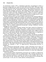
Practical experience shows that it is important to know how the
force is distributed over the length of the finger stroke.
In accordance with the kinematics used gripping force differs over
the entire stroke. The gripping force diagrams in table 3.16 show
that only the parallel jaw gripper with one wedge principle of
function, for example, will achieve a constant distribution of force
over the entire stroke.
circular and elliptic piston
surface
129
finger length L in mm
gripping force (P) 6 bar
and spring
200
1400
1200
1000
800
600
400
200
0
50 100 150 200
DWG 100
Mx = 55Nm
Fa = 1200N
My = 10Nm
Mz =
35 Nm
Mz=
45Nm
My=
45Nm
Mx=
95Nm
Fa = 800N
finger length L in mm
0 25 50 75 100 125
gripping force in N
0
200
400
600
800
1000
1200
1400
1600
gripping force diagram
gripping force in relation to
the finger length L at 6 bar
PGN 100 - 1
PGN 100 - 2
PGN 100 - 1 / AS/IS
PGN 100 - 2 / AS/IS
My=
70Nm
Mz=
80Nm
Mx=
100Nm
Fa = 2000N
finger length L in mm
gripping force in N
2500
2000
1500
1000
500
0
gripping force diagram
gripping force in relation to
the finger length L at 6 bar
PGN 100 - 1
PGN 100 - 2
PGN 100 - 1 / AS/IS
PGN 100 - 2 / AS/IS
0 25 50 75 100 125
gripper with serrated guides
for increased moment capacity
Getting To Grips With Handling Tasks
3
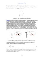
The length of the gripper fingers influences the forces and
moments occurring at the gripper kinematics. Therefore, gripping
force is frequently specified in relation to the finger length in such a
diagram to exclude overload or premature wear.
The characteristic curve for each gripper type shown in the gripping
force diagrams falls with increasing finger length. Most evident is
the difference between swivel grippers and grippers based on the
wedge principle of drive. The gently declining curve of the PGN
gripper and the nearly identical PGN plus 100 reflects high load
capacity and robust guides for long finger capability.
Figure 3.16 Different force distribution for various gripper types – maximum admissible forces and moments at the gripper fingers in
addition to the gripping force.
130
type of gripper kinematics drive stroke opening closing
2-finger parallel wedge principle
without GFM
pneumatisch 4 mm 0.04 s 0.4 s
2-finger parallel wedge principle
with GFM
pneumatisch 4 mm 0.05 s 0.03 s
3-finger concentric wedge principle pneumatisch 4 mm 0.03 s 0.03 s
2-finger parallel lever principle pneumatisch 4.5 mm 0.05 s 0.05 s
2-finger parallel rack and pinion pneumatisch 15 mm 0.045 s 0.06 s
The curve of angular grippers must obviously drop as in the exam-
ple of the DWG 100 by SCHUNK, falling from a gripping force
of 1,400N at 50mm finger length to a gripping force of 500N at
200mm finger length. This drop in gripping force, however,
is not only a matter of straining guides and bearings of the gripper
kinematics. The moment of an angular gripper, which is induced
through the extended lever arm of a finger into the kinematics,
counteracts the force of drive so that the piston must counteract
the latter.
Opening and closing time of mechanical grippers
In most applications cycle time or process time for performing a
handling task are essential for the efficiency of an automated
solution. Part of the entire process time is taken up by opening
or closing the gripper. Opening and closing times depend on the
length of stroke, on the type of drive, and on gripper kinematics.
A gripper with gripping force maintenance (GFM) will have different
opening and closing times as the spring force at opening must be
overcome. When closing the gripper the spring will function as a
support. As compared to other kinematics in table 3.21 the rack and
pinion principle does have the shortest opening and closing times
in relation to the stroke.
Table 3.21 Opening and closing times of various gripper constructions (GFM= gripping force maintenance)
131
iÌÌ}Ê/Ê
À«ÃÊ7ÌÊ>`}Ê/>ÃÃ
Î
>}}ÊÌiÊ«ÀiÃÃÕÀiÊÜÊÞÊyÕiViÊ}À««}ÊvÀViÊÜiÊ«i
}Ê>`ÊVÃ}ÊÌiÃÊÀi>ÊÌiÊÃ>iÊvÀÊ}À««iÀÃÊÜÌÕÌÊ}À««}Ê
vÀViÊ>Ìi>Vi°
À««}Ê«>Ì
ÊÃÕVViÃÃvÕÊ«VÊ«iÀ>ÌÊÀiµÕÀiÃÊÌiÊ}À««iÀÊÌÊ«iÊÊ>VVÀ
`>ViÊÜÌÊÌiÊvÀÊvÊÌiÊ}À««iÀÊ>ÜÃÊ>`ÊÌiÊ`ÀiVÌÊvÊÌiÊ
}À««iÀÊ>««À>V}ÊÌiÊÜÀ«iVi°Ê/iÀivÀi]ÊÌiÊw}iÀÊÃÌÀiÊ
iViÃÃ>ÀÞÊvÀÊÌiÊ«VÊ«iÀ>ÌÊÃÊV>i`ÊÀiµÕÀi`Ê>ÜÊÃÌÀiÊV°
ÃÊÕÃÌÀ>Ìi`ÊÊw}ÕÀiÃÊΰ£ÇÊ>`Êΰ£n]Ê>Ê}À««iÀÊii`ÃÊÌÊLiÊ«ii`Ê
vÕÀÌiÀÊvÀÊ>ÊÀ>`>Ê}À«]Ê°Êi°ÊÜiÊÌiÊ}À««iÀÊ>««À>ViÃÊÌiÊÜÀ
«iViÊvÀÊÌiÊÃ`iÃ]ÊÌ>ÊvÀÊ>Ê>Ý>Ê}À«]Ê°Êi°ÊÜiÊÌiÊ}À««iÀÊ
>««À>ViÃÊÌiÊÜÀ«iViÊvÀÊ>LÛi°ÊÊÀ`iÀÊÌÊ>Û`ÊVÃ]Ê
>Ê}À««iÀÊÜÌÊ>Ê}iÀÊÃÌÀiÊvÊÌiÊ>ÜÃÊii`ÃÊÌÊLiÊÃiiVÌi`ÊvÀÊ
ÌiÊÀ>`>Ê}À«ÊÀ>ÌiÀÊÌ>ÊvÀÊÌiÊ>Ý>Ê}À«°
/iÊÃV>i`ÊV>«}ÊÀiÃiÀÛiÊLÊ>`ÊÌiÊ«i}ÊÀiÃiÀÛiÊ>Ê>ÀiÊ
`ÃÌ>ViÃÊÌÊiÃÕÀiÊ>Ê`i}ÀiiÊvÊÃ>viÌÞÊÜÌÊÀi}>À`ÊÌÊÜÀ«iViÊ
`iðÊvÊÃiÊÜÀ«iViÃÊÃÕ`ÊViÊÕÌÊÃ}ÌÞÊÃ>iÀÊ
Ê`>iÌiÀÊ`ÕiÊÌÊ>Õv>VÌÕÀ}ÊÌiÀ>ViÊÌiÊV>«}ÊÀiÃiÀÛiÊ
V«iÃ>ÌiÃÊvÀÊÌ°Ê/ÕÃÊÌiÊ}À««iÀÊÃÊ>LiÊÌÊÃ>viÞÊ}À«ÊÜÀ
«iViÃÊÊV>ÃiÊvÊÃ>iÀÊÜÀ«iViÊ`iðÊ/iÊ«i}Ê
ÀiÃiÀÛiÊ«iÀÌÃÊvÕÀÌiÀÊ«i}ÊvÊÌiÊ}À««iÀÊÌ>ÊiViÃÃ>ÀÞÊvÀÊ
ÃÌ>`>À`ÊÜÀ«iViÊ`iÃÃÊÊÀ`iÀÊÌÊ>Û`ÊVÃÃÊV>ÕÃi`Ê
LÞÊÛiÀÃâi`ÊÜÀ«iVið
/iÊÃÌÀiÊÃÌ>Ìi`ÊÊ«À`ÕVÌÊëiVwV>ÌÃÊvÀÊi>VÊ}À««iÀÊÌÞ«iÊ
>ÞÊÀ>}iÊvÀÊ{ÊÌÊÓääÊvÀÊ«iÕ>ÌVÊ}À««iÀðÊÌÊÃÊ
«ÀÌ>ÌÊÌ>ÌÊÌiÊÃÌÀiÊÃÊëiVwi`Ê«iÀÊ}À««iÀÊ>Ü°ÊÀiµÕiÌÞ]Ê
}À««iÀÃÊ>ÀiÊëiV>ÞÊV>ÃÃwi`Ê>ÃÊÃÀÌÃÌÀiÊ>`Ê}ÃÌÀiÊ
}À««iÀðÊÃÊÌiÊ>iÊÃÕ}}iÃÌÃÊÃÀÌÃÌÀiÊ}À««iÀÃÊ>ÀiÊÕÃi`ÊvÀÊ
ÃÀÌÊ«i}Ê>`ÊVÃ}ÊÌiÃÊÀÊÊV>ÃiÊÜÀ«iViÊ>VViÃÃLÌÞÊ
`iÃÊÌÊ«iÀÌÊ}iÀÊÃÌÀið
£ÎÓ
b
a
c
b
a
c
Their housing determines the application options of mechanical
grippers because interfering edges must always be taken into
account. Collisions with the gripper in open position occur every
time the stroke has not been considered for or adapted to the size
of the housing. Possible pick situations of different workpieces
must be taken into consideration to avoid collisions. Long-stroke
grippers cover a broad range of workpiece dimensions and can be
used more flexibly for different workpiece sizes.
The decision for a particular gripper not only depends on work-
piece- and gripper-related characteristics but also to a great extent
on the ambient conditions of the pick operation.
Figure 3.17 Axial grip Figure 3.18 Radial grip
133
iÌÌ}Ê/Ê
À«ÃÊ7ÌÊ>`}Ê/>ÃÃ
Î
ΰ{Ê À««}Ê-ÌÕ>ÌÃÊ
ÃÊÌiÞÊÃÌÀ}ÞÊ>vviVÌÊ}À««iÀÊ`iÃ}ÊÛ>ÀÕÃÊ}À««}ÊÃÌÕ>ÌÃÊ
>ÀiÊ`iÃVÀLi`ÊÊÌiÊvÜ}°Ê/iÊvVÕÃÊÃÊÃiÌÊÊÜÊÜÀ«iViÃÊ
>ÀiÊ«ÀiÃiÌi`ÊÌÊÌiÊ}À««iÀÊvÀÊ«VÊ«iÀ>ÌðÊ
Ê
UÊ«V}ÊÕ«ÊÜÀ«iViÃÊÜÌÕÌÊÀ`iÀÊÃÌ>ÌÕÃʺ}À«Ê>ÌÊÀ>`»®
UÊ«V}ÊÕ«ÊÜÀ«iViÃÊÜÌÊÕÃÀÌi`ÊÀ`iÀÊÃÌ>ÌÕÃÊvÀÊ>Ê«>iÊ
ÃÕÀv>Vi]Êi°Ê}°Ê>ÊVÛiÞÀÊ
UÊ«V}ÊÕ«ÊÜÀ«iViÃÊÜÌÊÃÀÌi`ÊÀ`iÀÊÃÌ>ÌÕÃ]Êi°Ê}°ÊvÀÊ>Ê
ÜÀ«iViÊÃÕ««ÀÌ
/iÊ>LÛiÊÌ>ÃÃÊ>ÞÊ>}>ÊÛ>ÀÞÊ>VVÀ`}ÊÌÊÜiÌiÀÊÜÀ«iViÃÊ
>ÛiÊÌÊLiÊ«Vi`Ê>ÌÊÀiÃÌÊÀÊÊÌ°
ÀÊ«>ViÊ«iÀ>ÌÃÊÌiÊÀiëiVÌÛiÊÃVi>ÀÃÊ>««ÞÊÜÌÊiÊiÝVi«
Ì\Ê7À«iViÃÊ>ÀiÊÀ>ÀiÞÊ«>Vi`ÊÌÊ>ÊÕÃÀÌi`ÊÀ`iÀÊÃÌ>ÌÕÃÊ>ÃÊ
ÌiÞÊ>ÀiÊÕÃÕ>ÞÊ`iÃÀi`ÊÊÃÀÌi`ÊÀ`iÀÊÃÌ>ÌÕð
£Î{
Scenario 1: Workpieces Without Order Status
Picking up workpieces which are presented to the gripper without
any order status is referred to as “grip at random”. This expression
already suggests that it is hardly possible to calculate all eventual
collisions with the gripper jaws in advance. According to position
and orientation of the workpieces lying in a box at random, the
gripper fingers are faced with most different interfering edges of
the workpieces. Therefore, this gripping situation requires sensors
and subsequent safe actuation of the handling device. There are
exceptions to the rule, e. g. if workpieces are made of elastic
material and thus can be simply pushed aside by the operating
elements of the gripper.
In an entirely unsorted situation hardly any automated system can
cope. The “grip at random” has been repeatedly promoted and
demonstrated at trade fairs but such gripping systems are hardly
used in practice. Nevertheless, developing a sensor technology
necessary for analyzing the workpiece to be gripped under such
conditions is a major technical challenge. Using direct grip in such
undefined situations a gripper cannot be expected to perform a
reliable pick operation. Workpieces frequently have to be monitored
again after the pick operation to make sure that they have been
picked up safely. In addition to expensive sensor technology for
workpiece analysis, the pick operation must also be monitored.
So far the overall expense prevents an efficient use of grippers for
this kind of application.
For workpieces which undergo further processing it does not make
sense to reduce their order status by placing them into a box at
random. A gripper placing workpieces into a box is generally used
for reject goods as this undefined situation does not permit safe
product placing. The workpiece falls from an undefined height onto
other workpieces in the box which may cause workpiece damage.
135
'ETTING4O'RIPS7ITH(ANDLING4ASKS
3CENARIO7ORKPIECES7ITH5NSORTED/RDER3TATUS/N
0LANE3URFACE
)NCASEAWORKPIECEISISOLATEDFROMBULKGOODSORPRESENTEDTOA
GRIPPERONAPLANESURFACEVARIOUSSENSORSCANANALYZETHEPOSITION
ANDORIENTATIONOFTHEWORKPIECE!SMENTIONEDEARLIERWORKPIECE
GEOMETRYDETERMINESSOCALLEDPREFERREDWORKPIECEORIENTATION
WHICHALREADYCONTRIBUTESINFORMATIONTOWORKPIECEMONITORING
-ONITORINGSITUATIONSWHICHREQUIREMORETHANJUSTANALYZINGTHE
POSITIONOFSINGLEWORKPIECESAREAPROBLEM4HISMAYBETHECASE
WHENWORKPIECESOVERLAPEGIFTHEYAREVERYCLOSETOEACHOTHER
ORONTOPOFEACHOTHER
3UCHSPECIALCASESAREFREQUENTLYCOMPLICATEDBYPRODUCTOR
PRODUCTIONRELATEDEXCEPTIONS&ORPRODUCTPROCESSINGFOREXAMPLE
ONLYWORKPIECESOFPERFECTQUALITYAREDESIRED1UALITYREQUIREMENTS
AREMOSTDIVERSEEGSURFACEROUGHNESSFORMORCOLORJUSTTO
NAMEAFEW)TISONLYTHEWORKPIECESFULlLLINGTHESEREQUIREMENTS
WHICHARETOBEHANDLED4HISQUALITYASSURANCEISNOTPARTOFTHE
HANDLINGTASKITSELFBUTAPROJECTOFITSOWN)TMUSTBEENSUREDTHAT
THEHANDLINGSYSTEMISNOTCONFRONTEDWITHAWORKPIECEOFMINOR
QUALITYANDTHUSNOTHANDLINGTHEWRONGWORKPIECEFORNOTHING
1UALITYCRITERIAMUSTBECLEARLYDElNEDBEFORESTARTINGTOPROGRAM
ANIMAGEPROCESSINGORSCANNERSOFTWARE
7ORKPIECESMAYEVENHAPPENTOBEINAPOSITIONWHICHISNOT
SUITABLEFORPICKOPERATIONSATALLEGINCASEAWORKPIECECANFALL
INTOAPOSITIONWHEREITHIDESSUITABLECONTACTSURFACESFROMTHE
GRIPPER{SOPERATINGELEMENTS
OVERLAPPING
WORKPIECES
3UCCESSFULPICKOPERATIONSAREDEPENDENTONTHEHANDLINGSYSTEM{S
DEGREESOFFREEDOM4HESITUATIONFORWORKPIECECOMPOUNDSMAY
AGAINLEADTOCOLLISIONSBETWEENGRIPPERJAWSANDANYWORKPIECES
WHICHHAPPENTOBENEARTHEWORKPIECEDUEFORGRIPPING
)FTHEGRIPPINGSITUATIONISMONITOREDBYSENSORSTHEGRIPPERCANBE
POSITIONEDBYTHEHANDLINGSYSTEMTOAVOIDCOLLISIONS!CCORDINGTO
WORKPIECEPROXIMITYDURINGPREPARATIONANDTHEREQUIREDhGRIPPING
ZONEvAROUNDTHEGRIPPERITMAYOCCURTHATWORKPIECESCANNOTBE
PICKEDASPREPARED4HESEWORKPIECESWILLHAVETOREMAININPREPA
RATORYSTATEFORANOTHERTRY
4HEWORKPIECESWHICHHAVENOTBEENGRIPPEDTHElRSTTIME
BECAUSEOFTHEIRFAULTYDEGREEOFORIENTATIONORDUETOUNSUITABLE
GRIPPINGCONDITIONSEGWORKPIECESINDANGERTOBEDAMAGEDCAN
BEPREPAREDANEWFORTHEPICKOPERATION4HISSITUATIONFREQUENTLY
OCCURSWITHSMALLWORKPIECESFEDINGREATNUMBERS
0LACEOPERATIONSOFWORKPIECESUNDERSUCHCONDITIONSRUNSIMILAR
RISKSASDESCRIBEDINTHElRSTSCENARIOWORKPIECESMAYBEDAMAGED
ASWELL)FTHEWORKPIECEISNATURALLYSTABLEATLEASTTHEORDERSTATUS
CANBEMAINTAINEDWITHTHERESULTTHATAPICKOPERATIONFORFURTHER
PROCESSINGISMUCHEASIER
&IGURE)NTERFERINGEDGESOFWORK
PIECESINUNSORTEDORDERSTATUS
'ETTING4O'RIPS7ITH(ANDLING4ASKS
3CENARIO7ORKPIECES7ITH3ORTED/RDER3TATUS
&ORAREGULARPICKOPERATIONININDUSTRIALHANDLINGTHEWORKPIECEIS
NORMALLYPREPAREDINSORTEDORDERSTATUS4HEWORKPIECES{DEGREE
OFORIENTATIONISLARGELYMAINTAINEDWITHTHEHELPOFMANUFACTURING
TECHNOLOGYINORDERTOREALIZEGRIPPINGWITHOUTHAVINGTORESORTTO
EXPENSIVESENSORTECHNOLOGY#AREFULPLANNINGISESSENTIALTOAVOID
POSSIBLECOLLISIONSOFTHEGRIPPERlNGERSWITHADJOININGWORKPIECES
ORUNSUITABLEGRIPPERHOUSING
7ORKPIECESAREFREQUENTLYPREPAREDONPALLETSFORTHEPICKOPERATION
#ONSTRUCTIONENGINEERSTRYTOPACKASMANYWORKPIECESASCLOSEAS
POSSIBLEONAPALLETFORMAXIMUMWAREHOUSECAPACITY4HISOBJECTIVE
OFTENCLASHESWITHTHENEEDOFMAXIMUMGRIPPERmEXIBILITYFORWORK
PIECESOFVARIOUSDIAMETERS&IGURESHOWSTHATTHESELECTION
OFANAPPROPRIATEGRIPPERNOTONLYDEPENDSONTHEWORKPIECEITSELF
BUTONHOWITISPREPAREDONAPALLETLEAVINGTHESPACENECESSARY
FORTHEGRIPPERJAWSTOPICKITUPSAFELY
3IMILARCOLLISIONPRONESITUATIONSOCCURWHENWORKPIECESAREFED
INTOPROCESSINGMACHINES0ICKOPERATIONSWITHCHUCKSORSIMILAR
MAKEACCESSIBILITYDIFlCULT0ICKOPERATIONSWITHLATHECHUCKSAND
SHORTWORKPIECESAREAGREATCHALLENGEBECAUSETHEPOSITIONOFTHE
LATHECHUCKJAWSNEEDSTOBETAKENINTOACCOUNTFORTHEPICK
OPERATIONASWELL
&ORAPLACEOPERATIONTHEWORKPIECE{SWEIGHTNEEDSTOBECONSID
EREDASTHISFORCEMAYCAUSEITTOFALLOUTOFTHEGRIPPER5NWANTED
CHANGESINWORKPIECEPOSITIONMAYOCCURIFTHEGRIPPERISOPENED
BEFORETHEWORKPIECECANBESAFELYCLAMPEDAGAIN
&IGURE)NTERFERINGEDGESOF
WORKPIECESINSORTEDORDERSTATUS
Special Challenges For Grippers In Motion
More and more machines and component functions of production
systems are directly linked to each other. This interlinkage demands
continuous materials flow which possibly should exclude buffers as
the latter will frequently change a workpiece`s degree of orientation
and require additional investment resources. The three scenarios
for pick operations as described above often occur in case of inter-
linked machines overlapping with workpieces in motion.
Pick operations for workpieces in motion can be distinguished as
follows:
1. Pick operation without relative movement from gripper to
workpiece Vg
≠ Vw
2. Pick operation with relative movement from gripper to
workpiece Vg = Vw
Many handling systems already connect workpiece and gripper
movement and convert workpiece movement into the respective
gripper system of coordinates without any problem, i. e. synchro-
nizing workpiece movement with robot movement.
Problems occasionally arise when workpieces are picked in motion,
e. g. from a steadily moving conveyor, which may lead to positioning
errors at the place station. Figure 3.20 illustrates the problem of a
two-finger parallel jaw gripper trying to pick workpieces from
different positions on the conveyor.
In the first picture of table 3.21 the workpiece moves with its con-
tact surfaces, which are supposed to be touched by the jaws, in the
same direction as the conveyor. The handling system positions the
gripper above the workpiece and parallel to the movement direction
of the conveyor and synchronizes it with the latter.
139
&LEXIBLEWORKPIECEPREPARATIONFOR
MANUFACTURINGCARBODIESWITHTHE
HELPOFSYNCHRONIZEDROBOTMOVE
MENTS
'ETTING4O'RIPS7ITH(ANDLING4ASKS
direction of conveyor
d d d
divergence d
Synchronizing gripper and workpiece movement nearly equals
the workpiece situation at rest. Therefore, workpieces cannot be
misplaced during pick operations when the gripper closes with the
gripper jaws reaching the workpiece at the same time. In case the
gripper is not synchronized or positioned correctly in relation to the
conveyor, a divergence between workpiece and gripper occurs.
In a worst-case scenario this divergence may lead to a collision
between gripper jaws and workpiece. If workpiece contact surfaces
are aligned with the conveyor`s movement direction, it can be
assumed for a two-finger parallel jaw gripper that workpiece
positioning will not be influenced.
The second picture of figure 3.21 shows a workpiece with its
contact surfaces relevant for the pick operation moving vertically to
the direction of the conveyor. Synchronizing and positioning errors
may lead to faulty positioning of the workpiece within the gripper
as illustrated. This error is critical with regard to the subsequent
place operation.
If the workpiece contact surfaces are situated diagonally in relation
to the movement direction of the conveyor, velocity components
along and diagonally to this direction are the consequence of the
workpiece hitting the first gripper jaw. Thus the workpiece will not
able to reach the correct position within the gripper. It is evident
that accurate gripper positioning in relation to the workpiece is
essential for successful pick operations.
Figure 3.21 Workpiece divergence as a result of faulty synchronization during transport on conveyors
141