McGraw.Hill PIC Robotics A Beginners Guide to Robotics Projects Using the PIC Micro eBook-LiB Part 5 docx
Bạn đang xem bản rút gọn của tài liệu. Xem và tải ngay bản đầy đủ của tài liệu tại đây (402.29 KB, 20 trang )
TRISB Decimal 134 86 Hex Port B
Port B
Decimal 6 06 Hex
Binary
00000001
00000010
00000100
00001000
00010000
00100000
01000000
10000000
Power
of Two
2
0
= 1
2
1
= 2
2
2
= 4
2
3
= 8
2
4
= 16
2
5
= 32
2
6
= 64
2
7
= 128
Bit Weight/Values
Register Location
128 64 32 16 8 4 2 1
RB0
RB1
RB2
RB3
RB4
RB5
RB6
RB7
Binary
00000001
00000010
00000100
00001000
00010000
00100000
01000000
10000000
Power
of Two
2
0
= 1
2
1
= 2
2
2
= 4
2
3
= 8
2
4
= 16
2
5
= 32
2
6
= 64
2
7
= 128
Bit Weight/Values
Register Location
128 64 32 16 8 4 2 1
RB0
RB1
RB2
RB3
RB4
RB5
RB6
RB7
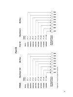
Figure 6.21 Diagram of port B registers.
67
68 Chapter Six
port B I/O pins. This correspondence between the bit number, bit weight, and
the I/O line is used to program and control the port.
Using the TRIS and port registers
The TRIS (tri-state enable) register is a 1-byte (8-bit) programmable register
on the PIC 16F84 that controls whether a particular I/O pin is configured as
an input or output pin. There is a TRIS register for each port. TRISA controls
the I/O status for the pins on port A, and TRISB controls the I/O status for the
pins on port B.
If one places a binary 0 at a bit location in TRISB for port B, the correspond-
ing pin location on port B will become an output pin. If one places a binary 1 at
a bit location in the TRISB, the corresponding pin on port B becomes an input
pin. The TRISB data memory address for port B is 134 (or 86h in hex).
After port B has been configured using the TRISB register, the user can read
or write to the port, using a port B address (decimal number 6).
Here is an example. Suppose we want to make all port B lines output lines.
To do so, we need to put a binary 0 in each bit position in the TRISB register.
So the number we would write into the register is decimal 0. Now all our I/O
lines are configured as output lines.
If we connect an LED to each output line, we can see a visual indication of
any number we write to port B. If we want to turn on the LEDs connected to
RB2 and RB6, we need to place a binary 1 at each bit position on port B reg-
ister. To accomplish this, we look at the bit weights associated with each line.
RB2 has a bit weight of 4, and RB6 has a bit weight of 64. We add these num-
bers (4
64 68) and write that number into the port B register.
When we write the number 68 into the port B register, the LEDs connected
to RB2 and RB6 will light.
To configure port A, we use the TRISA register, decimal address 133 (see Fig.
6.22). On port A, however, only the first 5 bits of the TRISA and the corre-
sponding I/O lines (RA0–RA4) are available for use. Examine the I/O pin-out
on the 16F84, and you will find there are only five I/O pins (RA0–RA4) corre-
sponding to port A. These pins are configured using the TRISA register and
used with the port A address.
Memory location, Memory location,
Register hexadecimal decimal
P
ort
A
05h 5
Port B 06h 6
TRISA 85h 133
TRISB
86h
134
On power up and reset, all the I/O pins of port B and port A are initial-
ized (configured) as input pins
.
W
e can change this configuration with our
program.
TRISA Decimal 133 85 Hex Port A
Port A
Decimal 5 05 Hex
Binary
00000001
00000010
00000100
00001000
00010000
Power
of Two
2
0
= 1
2
1
= 2
2
2
= 4
2
3
= 8
2
4
= 16
Bit Weight/Values
Register Location
16 8 4 2 1
RA0
RA1
RA2
RA3
RA4
Binary
00000001
00000010
00000100
00001000
00010000
Power
of Two
2
0
= 1
2
1
= 2
2
2
= 4
2
3
= 8
2
4
= 16
Bit Weight/Values
Register Location
16 8 4 2 1
RA0
RA1
RA2
RA3
RA4
Figure 6.22 Diagram of port A registers.
69
70 Chapter Six
Here’s another example. Let’s configure port B so that bit 0 (RB0) is an input
pin and all other pins are output lines. To place binary 0s and 1 in the proper
bit location, we use the bit weights shown in the binary number table. For
instance, to turn bit 0 on (1) and all other bits off (0), we would write the dec-
imal number 1 into TRISB for port B.
Depending upon which PicBasic compiler is used, the commands are a little
different. For the PicBasic compiler, the command to write to a register is the
poke command. The program line to write the decimal value 1 into the TRISB
register will look like this:
poke 134,1
The number after the poke command is the memory address that the com-
mand will write to, in this case 134. The number 134 is the memory address of
the TRISB for port B. The next number, separated by a comma, is the value we
want to write in that memory address. In this case it’s the number 1.
For the PicBasic Pro compiler, the TRISB and TRISA registers are already
predefined. Thus when the compiler sees TRISB, it accesses the proper memo-
ry (134) location. So the equivalent command for the PicBasic Pro is
TRISB = 1
Look at the binary equivalent of the decimal number 1:
0 0 0 0 0 0 0 1
Mentally place each 1 and 0 into the TRISB register locations shown in Fig.
6.21. See how the 1 fits into the bit 0 place, making that corresponding line an
input line, while all other bit locations have a 0 written in them, making them
output lines.
So by poking (writing) this location with a decimal number that represents
a binary number containing the proper sequence of bits (0s and 1s), we can
configure any pin in the port to be either an output or an input in any combi-
nation we might require. In addition, we can change the configuration of the
port “on the fly” as the program is running.
To summarize, writing a binary 1 into the TRIS register turns that corre-
sponding bit/pin on the port to an input pin. Likewise
, poking a binary 0 will
turn the bit into an output.
Accessing the ports for output
Once the port lines have been configured (input or output) using the TRIS reg-
ister, we can start using it. To output a binary number at the port, simply write
the number to the port, using the poke (PicBasic) or trisx.x (PicBasic Pro)
command. The binary equivalent of the decimal number will be outputted, as
shown in our first example. To output a high signal on RB3 using the PicBasic
compiler, we could use this command:
Testing the PIC Microcontroller 71
Figure 6.23 Schematic of eight LEDs connected to port B for counting program.
poke 6, 8
where 6 is the memory address for port B and 8 is the decimal equivalent of
the binary number (00001000) we want to output.
For the PicBasic Pro compiler, the equivalent command is
output portb.3 = 1
Counting program
To illustrate many of these concepts, I have written a simple basic program.
The schematic for the program is shown in Fig. 6.23. It is a binary counting
program that will light eight LEDs connected to port B’s eight output lines.
The counting program will light the LEDs in the sequence shown in the
binary number table. Each binary 1 in a number the table will be represented
with a lit LED. Every 250 milliseconds (ms) (
1
�
4
s), the count increments. After
reaching the binary number 255 (the maximum value of a byte), the sequence
repeats, starting from zero.
Counting in binary by 1
The following program is written for the PicBasic compiler
.
‘Program binary counting
‘Initialize variables
symbol trisb = 134 ‘Assign TRISB of port b to decimal value of 134
symbol portb = 6
‘Assign port b to decimal value of 6
‘Initialize port(s)
poke trisb,0 ‘Set port b pins to output
loop:
72 Chapter Six
for b0 = 0 to 255
poke portb, b0 ‘Place count at port b to light LEDs
pause 250 ‘Pause
1
�
4
s or it’s too fast to see
next b0 ‘Next counter value
goto loop ‘Start over again
‘End
The following program is written for the PicBasic Pro compiler.
‘Program binary counting
‘Initialize variables
ct var byte ‘Counting variable
‘Initialize port
trisb = 0 ‘Set port b pins to output
loop:
for ct = 0 to 255 ‘Counter
portb = ct ‘Place counter on port b to light LEDs
pause 250 ‘Pause
1
�
4
s
next ct ‘Next counter value
goto loop ‘Start over again
‘End
Input
The ability of our microcontroller to read the electrical status of its pin(s)
allows the microcontroller to see the outside world. The line (pin) status may
represent a switch, sensor, or electrical information from another circuit or
computer.
The button command
The PicBasic compiler comes equipped with a simple command to read the
electrical status of a pin, called the
button command. The button com-
mand, while useful, has a few limitations. One limitation of this command
is that it may only be used with the eight pins that make up port B. The I/O
pins available on port A cannot be read with the button command. Another
limitation is that you cannot read multiple port pin inputs at once, only one
pin at a time.
We will overcome these
button command limitations using the peek com-
mand.
But for the time being
,
let’s use and understand the
button command.
As the name implies, the
button command is made to read the status of
an electrical button switch connected to a port B pin. Figure 6.24 shows two
basic switch schematics, labeled A and B, of a simple switch connected to an
I/O pin.
The
button command structure is as follows:
button pin, down, delay, rate, var, action, label
Testing the PIC Microcontroller 73
Figure 6.24 Schematic of electric switches suitable for use
with PIC microcontrollers.
Pin Pin number (0–7), port B.
Down State of pin when button is pressed (0 or 1).
Delay Cycle count before auto repeat starts (0–255). If 0, no debounce or auto-
repeat is performed. If 255, debounce, but no auto-repeat is performed.
Rate Auto-repeat rate (0–255).
Var Byte variable used for delay/repeat countdown. Should be initialized to 0
prior to use.
Action State of button to perform
goto (0 if not pressed, 1 if pressed).
Label Execution resumes at this label if Action is true.
Let’s take another look at the switch schematic in Fig. 6.24 before we start
using the button switch. Let’s visualize how the switches affect the I/O pin
electrically.
The switch labeled A in Fig. 6.24 connects the I/O pin to a
5-V power sup-
ply through a 10,000-
resistor. With the switch open, the electrical status of
the I/O pin is kept high (binary 1). When the switch is closed, the I/O pin con-
nects to ground, and the status of the I/O pin is brought low (binary 0).
The switc
h labeled B in Fig. 6.24 has an electrical function opposite the
switch labeled A. In this case, when the switch is open, the I/O pin is connect-
ed to ground, keeping the I/O pin low (binary 0). When the switch is closed, the
I/O pin is brought high (binary 1).
In place of a switch, we can substitute an electric signal, high or low, that
can also be read using the
button command.
Typically the
button command is used inside a program loop, where the
program is looking for a change of state (switch closure). When the state of the
I/O pin (line) matches the state defined in the Down parameter, the program
execution jumps out of the loop to the label
portion of the program.
74 Chapter Six
A button example
If we want to read the status of a switch of I/O pin 7, here is a command we
will use in the next program.
button 7, 0,254,0,b1,1,loop
The next program is similar to the previous program 3, inasmuch as it per-
forms a binary counting. However, since we are using PB7 (pin 7) as an input,
and not an output, we lose its bit weight in the number we can output to port
B. The bit weight for pin 7 is 128. So without pin 7 we can only display num-
bers up to decimal number 127 (255
128 127). This is reflected in the first
loop (pin7/bit 7
128).
The program contains two loops. The first loop counts to 127, and the cur-
rent number’s binary equivalent is reflected by the Lite LEDs connected to
port B. The loop continues to count as long as the switch SW1 remains open.
When SW1 is closed, the
button command jumps out of loop 1 into loop 2.
Loop 2 is a noncounting loop where the program remains until switch SW1 is
reopened. You can switch back and forth between counting and noncounting
states. Figure 6.25 is a schematic of our button test circuit.
The following program is written for the PicBasic compiler.
‘Program for PicBasic compiler
symbol trisb = 134 ‘Set TRISB to 134
symbol portb = 6 ‘Set port b to 6
‘Initialize Port(s)
poke trisb,128 ‘Set port b pins (1-6 output), pin 7 input
Figure 6.25 Schematic of seven LEDs and one switch connected to port B for the switch detection and
counting program.
Testing the PIC Microcontroller 75
label 1: b1s = 0 ‘Set button variable to 0
loop1: ‘Counting loop
for b0 = 0 to 127
poke portb, b0 ‘Place b0 value at port to light LEDs
pause 250 ‘Pause counting or it’s too fast to see
button 7,0,254,0,b1,1,label2 ‘Check button status; if closed, jump
next b0 ‘Next b0 value
goto loop1
label12: b1=0 ‘Set button variable to 0
loop2: ‘Second loop not counting
poke portb,0 ‘Turn off all LEDs
button 7,1,254,0,b1,1,label1 ‘Check button status; if open, jump back
goto loop2
When the program is run, it begins counting. When the switch is closed, all the
LEDs will turn off, and it stops counting. Open the switch, and the counting
resumes, starting from 0.
‘Program for PicBasic Pro compiler
ct var byte
c1 var byte
‘Initialize port(s)
trisb = 128
label1: c1=0
loop1:
For ct = 0 to 127
portb = ct
pause 250
button 7,0,254,0,c1,1,label2
next ct
goto loop1
label2: c1=0
loop2:
portb =0
button 7,1,254,0,c1,1,label1
goto loop2
peek
‘Set port b pins (1-6 output), pin 7 input
‘Set button variable to 0
‘Counting loop
‘Place ct value at port to light LEDs
‘Pause counting or it’s too fast to see
‘Check button status; if closed, jump
‘Next counting value
‘Set button variable to 0
‘Second loop not counting
‘Turn off all LEDs
‘Check button status; if open, jump back
The peek command can only be used with the PicBasic compiler. We can also
use the peek command to check the status of any input line. The advantages
of the peek command are as follows. Using peek, we can read the five I/O
lines of port A (or the eight I/O lines of port B) at once. This increases the ver-
satility of the PIC chip and allows our program to be more concise (less con-
voluted), shorter, and easier to read.
To emphasize these points, let’s rewrite our last programs, using the
peek
command. This program uses the same schematic.
76 Chapter Six
‘PicBasic program that uses the peek command
‘Initialize port(s)
symbol trisb = 134 ‘Set TRISB to 134
symbol portb = 6 ‘Set port b to 6
poke trisb,128 ‘Set port b pins (1 6) output, pin 7 input
loop1: ‘Counting loop
for b0 = 0 to 127
poke portb, b0 ‘Place b0 value at port to light LEDs
pause 250 ‘Pause counting or it’s too fast to see
peek portb,b0 ‘Check button status
if bit7 = 0 then loop2 ‘If sw1 is closed, jump to loop2
next b0 ‘Next b0 value
goto loop1
loop2: ‘Second loop not counting
pke portb,0 ‘Turn off all LEDs
peek portb,b0 ‘Check button status; if open, jump back
if bit7 = 1 then loop1 ‘If sw1 is open, jump to loop 1
goto loop2
The variable b0 is performing double duty. First it is holding our current
counting numbers 0 through 127. The numbers 0 to 127 require 7 bits of the
variable b0 (bit 0 through bit 6). This leaves the eighth bit (bit 7) available for
use. We use bit 7 to check the status of the switch. If it’s open, its value will be
a binary 1; if it’s closed, it’s equal to binary 0.
The command
peek is followed by a memory address, then a comma, then a
storage variable.
peek address, var
As its name implies, the peek command allows one to view (or peek at) the
contents of a specified memory address. Typically the memory address “peeked
at” is one of the PIC microcontroller’s registers. The “peeked” value is stored in
a variable var defined in the command.
In this program we peeked at the one input line on port B:
peek portb,b0
The peek command can read an entire byte (8 bits) at once. Or as in this
case, only the upper bit (bit 7) of the peeked value is relevant. (The rest of the
bits are holding our counting number that’s outputted to the LEDs).
peek and PicBasic Pro
When you are using the PicBasic Pro compiler
,
it is recommended not
to use
the
peek command.
F
ortunately there is an easy work-around to the
peek
command. We simply assign a variable to the port we wish to peek at.
var = portb
Testing the PIC Microcontroller 77
The value placed in the variable var is our peek value.
‘PicBasic Pro program that uses a peek equivalent command
ct var byte
c1 var byte
‘Initialize port(s)
trisb = 128 ‘Set port b pins (1 6) output, pin 7 input
loop1: ‘Counting loop
for ct = 0 to 127
portb = ct ‘Place ct value at port to light LEDs
pause 250 ‘Pause counting or it’s too fast to see
c1 = portb ‘Check button status
if c1.7 = 0 then loop2 ‘If sw1 is closed, jump to loop2
next ct ‘Next ct value
goto loop1
loop2: ‘Second loop not counting
portb = 0 ‘Turn off all LEDs
c1 = portb ‘Check button status; if open, jump back
if c1.7 = 1 then loop1 ‘If sw1 is open, jump to loop 1
goto loop2
Basic input and output commands
In our programs we directly wrote to the PIC microcontroller TRIS registers
(A or B) and port registers. By doing so we were able to create input and out-
put pins and then access them in our programs. There are other commands
you can use to accomplish the same thing.
The PicBasic and PicBasic Pro compilers have two basic commands for mak-
ing individual pins either input or output lines. The commands are
input and
output. Unfortunately these two basic commands only work on port B pins
(0 to 7) for PicBasic. For PicBasic Pro, any port may be used. The command
input pin
makes the specified pin an input line. Only the pin number itself, that is, 0 to
7, is specified (i.e.,
not pin 0), for example,
input 2 ‘Makes pin2 (rb2) an input line.
The opposite of the input command is the output command. The command
output pin
makes the specified pin an output line. Only the pin number itself, that is, 0 to
7, is specified (i.e., not pin 0), for example,
output 0 ‘Makes port b, pin 0 (rb0) an output
The above examples are intended for use with either PicBasic or PicBasic Pro.
78 Chapter Six
The PicBasic Pro has an additional command structure that can be used
with both the input and output commands. This allows one to make input
and output pins on other ports besides port B. This is accomplished by speci-
fying the port and the pin.
For instance, to access port A, pin 2, you use the following format:
porta.2
To use this in a command:
input porta.2 ‘Make port a, pin 2 an input
output porta.3 ‘Make port a, pin 3 an output
Servomotors
Servomotors (see Fig. 6.26) are used in many radio-controlled model airplanes,
cars, boats, and helicopters. Because of this large hobbyist market, servomo-
tors are readily available in a number of stock sizes. Servomotors are used in
a few of our robots.
Primarily, servomotors are geared dc motors with a positional feedback con-
trol that allows the rotor to be positioned accurately. The specifications state
that the shaft can be positioned through a minimum of 90° (±45°). In reality
we can extend this range closer to 180° (±90°) by adjusting the positional con-
trol signal.
There are three wire leads to a servomotor. Two leads are for power
5 V
and GND. The third lead feeds a position control signal to the motor. The posi-
tion control signal is a single variable width pulse. The pulse can be varied
from 1 to 2 ms. The width of the pulse controls the position of the servomotor
shaft.
A 1-ms pulse rotates the shaft to the extreme counterclockwise (CCW) posi-
tion (45°
). A 1.5-ms pulse places the shaft in a neutral midpoint position (0°).
A 2-ms pulse rotates the shaft to the extreme CW position (45°).
The pulse width is sent to the servomotor approximately 50 times per sec-
ond (50 Hz). Figure 6.27 illustrates the relationship of pulse width to servo-
motor position.
In most of the robots that use servomotors
,
the servomotor must be posi-
tioned to its center location before being assembled into the robot. To center
the servomotor
,
we build a simple circuit and PicBasic program. The circuit is
shown in F
ig
.
6.28.
The programs for the PicBasic and PicBasic Pro compilers
follow:
‘PicBasic program to center servomotor
start:
pulsout 0, 150 ‘Send pulse out on rb0
pause 18 ‘Delay needed to send pulse at 55 Hz
goto start ‘Repeat
Testing the PIC Microcontroller 79
Figure 6.26 Photograph of a servomotor.
The following program is for the PicBasic Pro compiler.
‘PicBasic Pro program to center a servomotor
start:
pulsout portb.0, 150 ‘Send pulse out on rb0
pause 18 ‘Delay needed to send pulse at 55 Hz
goto start ‘Repeat
This centering program and circuit will be referred to in later parts of the
book when servomotors are discussed.
Parts List
LCD serial display
Pic Experimenter’s Board
A
vailable from Images SI Inc
. (see Suppliers at end of book).
Microcontroller (16F84)
$7.95
4.0-MHz Xtal
$2.50
80 Chapter Six
Figure 6.27 Diagram of pulse widths sent to control servomotor position.
Figure 6.28 Sc
hematic of servomotor circuit used to center servomotors
.
Testing the PIC Microcontroller 81
(2) 22-pF capacitors
(1) Solderless breadboard RadioShack PN# 276-175
(1) 0.1-F capacitor
RadioShack PN# 272-1069
(2) Red LEDs RadioShack PN# 276-208
(2) 470-
resistors*
RadioShack PN# 270-1115
(1) 4.7-k resistor
RadioShack PN# 271-1126
(1) Voltage regulator (7805) RadioShack PN# 276-1770
(1) 9-V battery clip RadioShack PN# 270-325
Available from RadioShack, Images SI Inc., Jameco Electronics, and JDR
Microdevices (see Suppliers).
*These resistors are also available in 16-pin dip package.
This page intentionally left blank.
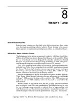
7
Chapter
Intelligence
Programming intelligence into a robot (or computer) is a difficult task and one
that has not been very successful to date even when supercomputers are used.
This is not to say that robots cannot be programmed to perform very useful,
detailed, and difficult tasks; they are. Some tasks are impossible for humans
to perform quickly and productively. For instance, imagine trying to solder 28
filament wires to a
1
�
4
-in square sliver of silicon in 2 s to make an integrated-
circuit chip. It’s not very likely that a human would be able to accomplish this
task without a machine. But machine task performance, as impressive as it is,
isn’t intelligence.
Approaches to Building Intelligence
There are two schools of thought concerning the creation of intelligence in arti-
ficial systems. The first approach programs an expert system (top down); the
second is a neural or behavior-based system (bottom up).
The expert system uses rules to guide the robot in task performance.
Behavior-based programs create an “artificial” behavior in the robot that caus-
es it to reflectively (automatically) perform the task required. Behaviors may
be programmed
(software) or may be hardwired into the robot. Behavior-based
intelligence doesn’t require a central processor, although such a system may
have one.
Let’s look at a practical programming problem and see how each approach
differs. Suppose you worked for a company that designed a new robotic vacu-
um cleaner. The purpose of the robot is to vacuum the floor of a customer’s
home or apartment. Your job is to program the navigation system. The robot
needs to move autonomously throughout the house
.
How would you go about
programming the robot to accomplish navigation around the home so it could
travel in and out of rooms without destroying the place?
Copyright © 2004 The McGraw-Hill Companies. Click here for terms of use.
83
84 Chapter Seven
Let’s assume you first decide to try an expert navigation system. This
approach uses brute-force programming and a lot of memory. You might begin
by dividing the task of vacuuming the apartment or home into smaller tasks
such as vacuuming individual rooms. You begin by programming into the
robot’s memory an electronic map (floor plan) of the home or area where the
robot needs to vacuum. Then you map out each individual room and its con-
tents. The robot must have the ability to measure its movement as it moves as
well as compass direction to maintain its location integrity. Once this is accom-
plished, the robot must have an exact start location on the floor plan.
The robot’s movement from the start position is measured and plotted on its
internal floor plan map. Problems occur if an object is positioned differently or
is out of place, such as a trash receptacle or chair that has been moved. In this
situation the real world does not match the robot’s internal map. Similar prob-
lems occur if new objects are left on the floor such as a bag, toy, or pet.
Even so, these obstacles would not present too much of a problem for an
expert system. To compensate, a secondary collision detection subprogram
could be written to detect, map, and go around an obstacle not existing on the
internal map. The robot continues to move and vacuum the floor. Keep in mind
that as the robot navigates around new obstacles, it’s continually updating its
internal map as it travels, to maintain its location integrity. These tasks are
gobbling up computer time and memory.
The robot vacuum accomplished its task. Now suppose you want to share
this robot or rent it. Now you have a problem. Each new house and every room
in the new house would require its own electronic map. Although expert pro-
gramming does work, it tends to be inflexible and not adaptive toward new or
innovative situations.
Now let’s try the other approach that uses behavior-based or bottom-up pro-
gramming. Instead of programming internal maps, we program sensor
responses and behavior-based algorithms (feedforward and feedback loops) for
sensing and traveling around obstacles and avoiding getting stuck underneath
furniture or trapped in corners. Without any internal map we allow the robot
to travel and move around the house in a random manner. The idea is that
while traveling in a haphazard manner, it will eventually make its way
throughout the rooms,
cleaning the floor as it goes. Because the robot travels
randomly, it will take longer for the robot to vacuum the entire floor, and it
may miss a spot here and there, but it gets the job done. Since this behavior-
based type of robot vacuum isn’t programmed for a particular house or room,
it may be used in any house in any room at any time.
While our example is simple, it does illustrate the main differences between
expert and behavior-based (neural) programming. But let’s look at just one
more example before we move on.
Expert systems typically have all the answers that the designers believe will
be required by the system programmed into the system before it begins. It may
store and categorize new information, but based on previously determined cat-
egories and existing knowledge. An example of this system could be a rock
Intelligence 85
identification system. The robot examines unknown rocks based on known
characteristics of rocks, such as color, hardness, scratchability, acid reaction
tests, mass, etc. The expert system fails if it inadvertently picks up a piece of
ice that melts to water during the tests. Well, it fails as long as the designer(s)
never anticipated the robot picking up a piece of ice by mistake and made
allowances for it.
Neural (behavior-based) systems are not programmed and are more adap-
tive, as shown in the previous example. But is a neural system suitable for this
task of rock identification? Probably not! There are instances in which expert
systems are the method of choice. One shouldn’t blindly assume one system is
better than the other in all cases.
To date, behavior-based robots are more successful at task accomplishments
such as traveling over unfamiliar and rough terrain than are programmed
robots. (Other neural-based intelligence includes speech recognition, artificial
vision, speech generation, complex analysis of stock market data, and life
insurance policies.)
Where’s the Intelligence?
Behavior-based systems at their most basic level are neural reflex actions, so
where’s the intelligence in that? However, true behavior-based systems, when
layered on top of one another, generate what appears to be (meaning to us
homo sapiens) intelligence actions. This is not a consciousness mind, which is
a whole other category of intelligence, but the layer behavior-based circuits
mimic intelligent actions quite convincingly.
Layered Behavioral Responses
Let’s layer a few behavioral responses on top of one another to see how intel-
ligence behavior emerges. This particular robot is a modified “photovore.” It
will use a number of standard photoresistors as sensors.
Layer 1 is a simple on and off system. It uses a single photoresistor to read
ambient light intensity. In darkness the system turns itself off and shuts down
all electric power to the robot. When the ambient light increases to a low
threshold, the system turns itself on and the robot travels forward slowly.
Layer 2 is a two-photoresistor sensor. It determines in which direction the
light intensity is greater. These sensors steer the robot in the direction of the
greatest light intensity.
Layer 3 is a single-photoresistor sensor. Under high-intensity light it shuts
down the robot’s drive system and allows the robot to bathe in strong-intensi-
ty light.
An outsider who didn’t know how this robot was wired would observe the fol-
lowing behavior. At night the robot sleeps. At dawn it begins to travel, looking
for a bright light source (food). When it finds a sufficiently bright light source,
it stops to feed, recharging its batteries through solar panels.
86 Chapter Seven
So our simple photovore robot exhibits three (dare we say intelligent?)
behaviors—sleep, searching or hunting, and feeding. That’s not bad for a hand-
ful of components and some neural glue.
Behavior-Based Robotics
Behavior-based programs and robotics are not new concepts. Seminal work
has been written and experiments carried out since the 1940s. In the 1940s
neural networks and behavior-based robotics were hardwired electrical com-
ponents.
In the 1940s Dr. W. Grey Walter built two turtlelike mobile robots that exhib-
it complex behavior using a few electrical neurons. The behavior generated
was at the time called robotic reflexes. Today this behavior is more accurately
described as layered neural architecture.
In the 1980s Valentino Braitenberg wrote a book entitled Vehicles—
Experiments in Synthetic Psychology in which he described complex behavior
emerging from the use of a few artificial neurons.
Rodney Brooks, head of MIT’s Artificial Intelligence Laboratory, is a leader
in the field of subsumption architecture, which again is behavior-based and
neural.
Mark Tilden, creator of the nervous network technology, which again is
reflex-based, doesn’t program strategies such as walking into his biomorphic
robots. Instead he creates a nervous network whose desired state creates a
walking gait.
What these scientists have discovered is that neural behavior-based archi-
tecture offers unique advantages over standard-based expert programming.
In this book we will build a few behavior-based robots, using the PIC micro-
controller extensively in their construction.